Operation Manual - ASSMANN IT-Solutions AG
Operation Manual - ASSMANN IT-Solutions AG
Operation Manual - ASSMANN IT-Solutions AG
- No tags were found...

Create successful ePaper yourself
Turn your PDF publications into a flip-book with our unique Google optimized e-Paper software.
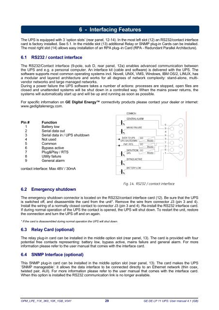
6 - Interfacing FeaturesThe UPS is equipped with 3 ‘option slots’ (rear panel, 12-14). In the most left slot (12) an RS232/contact interfacecard is factory installed. See 5.1. In the middle slot (13) additional Relay or SNMP plug-in Cards can be installed.The most right slot (14) allows easy installation of an RPA plug–in Card (RPA - Redundant Parallel Architecture).6.1 RS232 / contact interfaceThe RS232/Contact interface (9-pole, sub D, rear panel, 12a) enables advanced communication betweenthe UPS and e.g. a personal computer. An interface kit (cable and software) is delivered with the UPS. Thesoftware supports most common operating systems incl. Novell, UNIX, VMS, Windows, IBM OS/2, LINUX, hasa modular and layered architecture and works for all degrees of network complexity: stand-alone, multivendornetworks and large managed networks.During a power failure the UPS software takes a number of actions: processes are stopped, open files areclosed and unattended systems will be shut down in a controlled way. When the mains power returns, thesystems will automatically start up and will be up and running as soon as possible.For specific information on GE Digital Energy connectivity products please contact your dealer or internet:www.gedigitalenergy.com.Pin # Function1 Battery low2 Serial data out3 Serial data in / UPS shutdown4 Not used5 Common6 Bypass active7 Plug&Play / RTS8 Utility failure9 General alarmcontact interface: Max 48V / 30mA6.2 Emergency shutdownFig. 14. RS232 / contact interfaceThe emergency shutdown connector is located on the RS232/contact interface card (12). Be sure that the UPSis switched off, and disassemble the card from the unit*. Remove the wire from connector J3 (pin 3 and 4).Install the wiring of a normally closed contact to connector J3 (pin 3 and 4). Re-install the RS232 interface card.If during normal operation of the UPS the contact is opened, the UPS will shut down. To restart the unit, restorethe connection and turn the UPS off and on again.* If the card is disassembled during normal operation the UPS will shut down.6.3 Relay Card (optional)The relay plug-in card can be installed in the middle option slot (rear panel, 13). The card is provided with fourpotential free contacts representing: battery low, bypass active, mains failure and general alarm. For moreinformation please refer to the user manual that comes with the interface card.6.4 SNMP Interface (optional)This SNMP plug-in card can be installed in the middle option slot (rear panel, 13). The card makes the UPS‘SNMP manageable’: it allows the data interface to be connected directly to an Ethernet network (thin coax,twisted pair, AUI). For more information please refer to the user manual that comes with the interface card.When this option is installed the RS232 communication link is no longer available.OPM_LPE_11X_3K0_10K_1GB_V041 29 GE DE LP 11 UPS: User manual 4.1 (GB)