Operation Manual - ASSMANN IT-Solutions AG
Operation Manual - ASSMANN IT-Solutions AG
Operation Manual - ASSMANN IT-Solutions AG
- No tags were found...

Create successful ePaper yourself
Turn your PDF publications into a flip-book with our unique Google optimized e-Paper software.
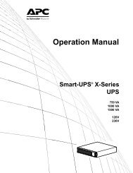
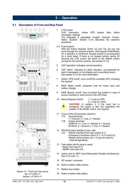
5.1 Description of Front and Rear Panel5 - <strong>Operation</strong>65124 31 LCD screen2x16 characters, shows UPS system data, statusmessages, settings.The language is selectable: English, German, French,Italian, Spanish. Section 5.3.4 describes the selectionprocedure.101111a11b78 9171512131412a182-4 Push-buttonsWith the button keypads ‘Down’ (2) and ‘Up’ (4) you canscroll through the several screens, with keypad 'Enter/Reset'(3) a selection is confirmed. Keypad activity is accompaniedby a short beep. If there is no keypad activity during 20seconds the LCD screen will return to the default screen(except for the service screens, see section 5.3.3).5 LED 'operation' indicates normal operation.6 LED ‘alarm’, indicates an alarm situation, accompanied byalarm message(s) on the display and a sounding buzzer.See section 5.3.2 for more information.7 Switch ‘UPS on/off’, turns on/off the complete UPS, includingthe bypass!8 MCB ‘Mains on/off’, protection fuse for mains input andbattery charger.9 MCB ‘Bypass on/off’, fuse to protect the system in case ofsevere overload or short circuit in the UPS load.10 <strong>Manual</strong> Bypass Switch: 1 = Load on UPS2 = Load on mainsCAUTION: In position 2, if the input line isenergized, the output is also live regardless theposition of the MCBs ‘mains’ and ‘bypass’.1011a11b11 Cover of the I/O terminals, behind it:11A Input terminals1 = Ground, 2 = Line, 3 = Neutral11B Output terminals3/5/6kVA: 4 = Line, 5 = Neutral, 6 = Ground8/10kVA: 4 = Ground, 5 = Line, 6 = Neutral15111778914131212a1812 RS232/Contact Interface Card, with:12a - RS232 Interface Port (see section 6.1)- Emergency shutdown (see 4.5.1 / 4.5.3 and 6.2)- Battery disconnected, pin 1-2 (can be used forexternal signalling).13 Free option slot for plug-in cards:- Relay Card (see 6.3)- SNMP Card (see 6.4)14 Option slot for RPA Card (Redundant Parallel Architecture).See 4.5.5 and 7.3.1615 DC socket / connector.16 Slots to fasten cable clamps.Figure 12. Front and rear paneltop: LP 3/5/6-11bottom: LP 8/10-1117 Battery fuse holder.18 Holes to fasten data cables.OPM_LPE_11X_3K0_10K_1GB_V041 16 GE DE LP 11 UPS: User manual 4.1 (GB)