Operation Manual - ASSMANN IT-Solutions AG
Operation Manual - ASSMANN IT-Solutions AG
Operation Manual - ASSMANN IT-Solutions AG
- No tags were found...

Create successful ePaper yourself
Turn your PDF publications into a flip-book with our unique Google optimized e-Paper software.
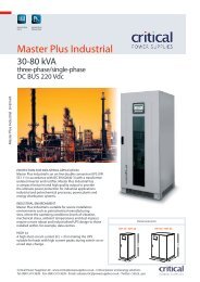
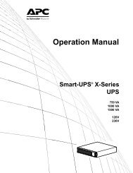
2 - Introduction2.1 DescriptionMore than ever before, today's advanced electronic equipment, with complex integrated circuits and othersensitive electronics, needs a stable and continuous AC power supply to operate correctly. While the powercoming from the wall outlet is often unreliable, a GE Digital Energy LP UPS provides the security ofcompletely uninterrupted power.A compact, truly on-line system, the LP UPS protects your equipment from all forms of power interference,including complete power failure. A simple and elegant circuit design, together with extensive protection againstabnormal operating conditions (e.g. overload, short circuit, overheating), makes the LP UPS exceptionallyreliable.Figure 1. The GE Digital Energy LP 11 UPS: 3/5/6-11 (front) and 8/10-11 (rear)2.2 WarrantyGE Digital Energy, operating through its authorized agents, warrants that the standard products will be free ofdefects in materials and workmanship for a period of 24 months (12 months for the battery) after the date ofinvoice, or such other period as may be specified.NOTE: This warranty does not cover failures of the product which result from incorrect installation,misuse, alterations by persons other than authorized agents, or abnormal operating conditions.OPM_LPE_11X_3K0_10K_1GB_V041 5 GE DE LP 11 UPS: User manual 4.1 (GB)
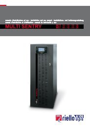
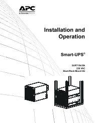
3.1 The Principles of <strong>Operation</strong>3 - Functional ExplanationThe UPS stores electric energy in batteries. This allows the UPS to supply output power even when theincoming utility power is cut off completely.Energy is stored as Direct Current (DC), while input and output energy must be Alternating Current (AC).Therefore the UPS contains an input converter (AC to DC) and an output converter (DC to AC). (fig.2)3.2 Normal ConditionsUnder normal conditions, energy from the utility is channelled through the input converter, which supplies theoutput converter and the battery charger. The batteries are kept in a fully charged state, and the outputconverter synthesizes a completely new AC output sine wave to supply the load (electrical equipment).INPUT:MAINS POWER W<strong>IT</strong>H DISTURBANCESOUTPUT:PERFECT UPS POWERMANUAL BYPASS SW<strong>IT</strong>CH1-PHASEMAINS INPUTBYPASSFILTERRFIFILTERTO LOADRFIFILTERINPUTCONVERTER/BATTERYCHARGEROUTPUTCONVERTERAUTOMATICBYPASSSW<strong>IT</strong>CHOPTIONSLOTS FOR:RPA CARDSNMP CARDOPTIONALRELAY CARDBATTERYEXTENSIONBATTERYMICROPROCESSOR CONTROLSYSTEMON/OFFFRONTPANELSTANDARDINSTALLED:RS232/CONTACTINTERFACE3.3 Utility FailureFigure 2. Block diagram of the LP 11 UPS, mains presentIn the event of a utility power failure (i.e. absent or outside tolerance) the system uses the energy reservestored in the battery to continue to produce AC power, ensuring unbroken output (fig. 3). No interruption oralteration will ever be noticed in the output power.In the event of an extended utility failure, the output converter will stop when the battery has been discharged.At this point, the UPS is no longer able to power the connected equipment.When the utility is re-established within tolerance, the output converter will restart automatically (if stopped, seeabove) and will be supplied again by the input converter. The batteries will be recharged, making them ready tosupport future power failures.NO INPUT:MAINS FAILURE (BLACK OUT)OUTPUT:PERFECT UPS POWERMANUAL BYPASS SW<strong>IT</strong>CHBYPASSFILTERRFIFILTERTO LOADRFIFILTERINPUTCONVERTER/BATTERYCHARGEROUTPUTCONVERTERAUTOMATICBYPASSSW<strong>IT</strong>CHOPTIONSLOTS FOR:RPA CARDSNMP CARDOPTIONALRELAY CARDBATTERYEXTENSIONBATTERYMICROPROCESSOR CONTROLSYSTEMON/OFFFRONTPANELSTANDARDINSTALLED:RS232/CONTACTINTERFACEFigure 3. Block diagram of the LP 11 UPS, utility failureOPM_LPE_11X_3K0_10K_1GB_V041 6 GE DE LP 11 UPS: User manual 4.1 (GB)
3.4 Automatic Bypass SwitchIf the output converter is unable to deliver the demanded output power because of overload or overtemperature,the automatic bypass switch will automatically transfer the load to the utility. When the situation is corrected theUPS will switch back to normal operation, i.e. the load is transferred back to the output converter. Though theautomatic bypass switch is shown as a simple mechanical switch in figures 2-5, the transfers are done bymeans of thyristors, i.e. electronically, without any interruption of the power supplied to the load.In case of a severe overload or short-circuit the magnetic bypass circuit breaker (rear panel) may trip in order toprotect the UPS. If the current is insufficiently high to trip the breaker, the UPS will be switched off by thesoftware in order to protect the UPS and connected equipment.MANUAL BYPASS SW<strong>IT</strong>CH1-PHASEMAINS INPUTBYPASSFILTERRFIFILTERTO LOADRFIFILTERINPUTCONVERTER/BATTERYCHARGEROUTPUTCONVERTERAUTOMATICBYPASSSW<strong>IT</strong>CHOPTIONSLOTS FOR:RPA CARDSNMP CARDOPTIONALRELAY CARDBATTERYEXTENSIONBATTERYMICROPROCESSOR CONTROLSYSTEMON/OFFFRONTPANELSTANDARDINSTALLED:RS232/CONTACTINTERFACEFigure 4. Bypass operation: automatic bypassIf a power failure occurs during bypass operation, load power is lost. If the UPS functions under overloadconditions it may not be able to protect the load.3.5 <strong>Manual</strong> Bypass Switch (Service switch)The system can be bypassed manually using the manual bypass switch located at the rear panel. It is a twopositionswitch: the normal position is '1': as in figures 2-4. Position '2' is the service position: the load is directlyconnected to the utility input. This way maintenance of the UPS (e.g. battery replacement, as in fig. 5) ispossible without interruption of the power supplied to the load.CAUTION: REFER SERVICE TO QUALIFIED PERSONNEL ONLY.MANUAL BYPASS SW<strong>IT</strong>CH1-PHASEMAINS INPUTBYPASSFILTERRFIFILTERTO LOADRFIFILTERINPUTCONVERTER/BATTERYCHARGEROUTPUTCONVERTERAUTOMATICBYPASSSW<strong>IT</strong>CHOPTIONSLOTS FOR:RPA CARDSNMP CARDOPTIONALRELAY CARDBATTERYEXTENSIONMICROPROCESSOR CONTROLSYSTEMON/OFFFRONTPANELSTANDARDINSTALLED:RS232/CONTACTINTERFACEFigure 5. Bypass operation: manual bypassOPM_LPE_11X_3K0_10K_1GB_V041 7 GE DE LP 11 UPS: User manual 4.1 (GB)
4 - Installation4.1 Transport4.2 UnpackingNOTE: Transport the UPS only in upright position. Check for sufficient floor and elevation loadingcapacity. Move the UPS in its original package to the final destination room. Do not stack otherpackage on top.Cut the two wrapping bands, and remove the shipping box. Loosen the four bolts with which the UPS is fixed tothe pallet. Remove the UPS from the pallet.BE CAREFUL! Pay attention to the HEAVY WEIGHT of the UPS when downloading the UPSfrom the pallet! Never try to lift the unit by yourself!The UPS is equipped with castors, which allow easy displacement of the unit. Please take appropriatemeasures to avoid damage on vulnerable floors.4.3 Package ContentsThe shipping box contains a LP 11 UPS, a CD-ROM, an RS232 cable, cable clamps, a safety guide and thismanual. If the UPS is equipped with an RPA plug-in card (Redundant Parallel Architecture, right option slot atthe rear of the unit) the shipping box also contains a yellow network cable and one bus terminator. Inspect theUPS for damage after unpacking. If any damage is present please notify the carrier and place of purchaseimmediately.4.4 LocationPlease refer to sections 1.2 and 1.3 of ‘IMPORTANT SAFETY INSTRUCTIONS’.4.5 InstallationIMPORTANT:Before making any connection and switching on the LP UPS, please check the following conditions:- the voltage and frequency of your utility supply is 220/230/240 Vac and 50/(60) Hz; off-factory the outputof the UPS is set to 230 Vac / 50 Hz,- the branch circuit supply is protected as follows:UPS modelLP 3kVALP 5/6kVALP 8kVALP 10kVAbranch protection16A slow25A slow50A slow50A slowTable 1. external input fuse valueCAUTION: To reduce risk of fire, connect the UPS only to a circuit provided with the fusevalues according to Table 1 above.- Ensure that the total power requirement of the equipment to be protected does not exceed the ratedoutput power of the UPS (output power for your unit is indicated on the rating label on the rear panel).- The UPS must be grounded when in use: Connect the UPS to a single phase, three wire AC sourceequipped with an earth connection.The following sections describe the installation of the LP 11 UPS.LP 3/5/6-11 UPS: 4.5.1 and 4.5.2LP 8/10-11 UPS: 4.5.3 and 4.5.4LP 11 UPS, general: 4.5.5OPM_LPE_11X_3K0_10K_1GB_V041 8 GE DE LP 11 UPS: User manual 4.1 (GB)
4.5.1 LP 3/5/6-11: standard installation procedureIf a battery extension pack is to be installed, please proceed with section 4.5.2.If 2, 3 or 4 parallel operating units will be installed, please proceed with section 4.5.5.The numbers between (brackets) refer to figure 12 in section 5.1.1. Make sure that all circuit breakers (7-8-9) are in ‘off’position (down).12. Loosen the 3 screws and remove the metal cover (11)of the I/O terminals.233. Lead the input/output cables through the swivels ofthe metal cover (11).4. Input (11a). Connect the mains supply wires to theterminals 2 (Line) and 3 (Neutral) and the ground wireto terminal 1. Ground connection is essential!5. Output (11b). Connect the load wires to the terminals4 (Line) and 5 (Neutral) and the ground wire toterminal 6. Ground connection is essential!6. Re-install the metal cover (11). Fasten the cables in theswivels. Insert the battery fuse in the fuse holder (17)and close the fuse holder.457. An emergency shutdown switch can be connected toconnector J3 on the RS232/Contact Interface Card,between pins 3 and 4. See section 6.2 for moreinformation.68. For advanced communication possibilities, theRS232/contact interface port (12a) can be connectedto a computer system. See section 6.1 for moreinformation. *9. The middle ‘option slot’ (13) allows easy installation ofplug-in cards: SNMP Card or Relay Card. Seesections 6.3 and 6.4 for more information. *78see 6.3-4BATTERYDISCONNECTEDEMERGENCYSHUTDOWNstand-aloneand RPA cardavailable10. The right ‘option slot’ (14) allows easy installation ofthe RPA-card (Redundant Parallel Architecture). If thecard is already mounted, and if the unit is intended tobe used stand-alone, a bus terminator (delivered withthe unit) has to be placed in one of the two busconnectors on the card. If the unit will be part of aparallel system, see sections 4.5.5 and 7.3 for moreinformation. *910see 4.5.5 / 7.3* The data cables can be attached to the cabinet withtie-wraps, position the tie-wraps in the small holes(18) underneath the option slots.Figure 6. LP 3/5/6-11:Standard installation procedure11. Connect the utility power to the UPS.12. For a quick start proceed with section 5.2 ‘Start-up’.OPM_LPE_11X_3K0_10K_1GB_V041 9 GE DE LP 11 UPS: User manual 4.1 (GB)
4.5.2 LP 3/5/6-11: installation of GE Digital Energy LP battery extension pack(s)The numbers between (brackets) refer to figures 12-13 in section 5.1.Battery extension pack(s) are shipped with all materialsnecessary to connect them to the UPS. The pack(s) canbe connected to the DC connector (15) at the rear panel ofthe UPS. We recommend to switch off the UPS beforeproceeding: be sure that the UPS can be switched offwithout causing damage to the load, and turn all circuitbreakers (7-8-9) into ‘off’ position (down).1231. Open the fuse holders at the rear panel of the UPS(17) and battery pack (18) and make sure that thefuses have been removed.2. UPS rear panel: loosen the 4 screws that hold thecover of the DC connector (15), and open the cover.The actual DC socket is fixed to the inner side of thecover.CAUTION! The battery voltage is 240Vdcand is NOT isolated from the mains.3. Break out a part of the cover: a large part (grey in fig.7) if your battery extension pack is equipped with aswivel (19, fig. 13a), otherwise a small part. Ifapplicable, mount the swivel in the cover.4. Connect the DC connector of the battery pack (15a)to the DC socket of the UPS (15). You will hear a clickwhen the cable is properly installed.5. If applicable lead the DC cable through the hole onthe left side of the cover. Re-install the cover. Fastenit with 4 screws.6. In case of 14Ah battery packs: using the DCconnector of the battery pack (15) you can install asecond, third, etc. pack. 7Ah battery packs cannot beconnected in series.7. Insert the battery fuse of the UPS (17). Insert the 2(7Ah) or 4 (14Ah) fuses of the (each) battery pack(18). Close the fuse holders (17, 18).48. In order to calculate the available back-up time relatedto the actual load, information on the capacity of thebattery set is stored in the UPS. As the total batterycapacity changes when battery extension packs areinstalled, the battery capacity must be reprogrammed.See 5.3.4.5Figure 7. LP 3/5/6-11:Installation of battery packIn case of a custom-built battery extension set you maywant to install a ‘battery disconnected’ alarm device.9. Be sure that the UPS is switched off, anddisassemble the RS232/Contact Interface Card (12)from the unit. If the card is disassembled duringnormal operation the UPS will shut down!Remove the wire from connector J3 (pin 1 and 2).Install the wiring of a normally closed contact (e.g. anauxiliary contact of an MCB) to pin 1 and 2. Re-installthe interface card. If the contact is opened, the UPSwill generate an ‘EXTERNAL BATTERY FUSEFAILURE’. See 5.3.2 for more information.Proceed with 4.5.1 or 5.2.OPM_LPE_11X_3K0_10K_1GB_V041 10 GE DE LP 11 UPS: User manual 4.1 (GB)
4.5.3 LP 8/10-11: standard installation procedureIf a battery extension pack is to be installed, please proceed with section 4.5.4.If 2, 3 or 4 parallel operating units will be installed, please proceed with section 4.5.5.The numbers between (brackets) refer to figure 12 in section 5.1.1. Make sure that all circuit breakers (7-8-9) are in ‘off’position (down).12. Loosen the 5 screws and remove the metal plate (11)that covers the I/O terminals.23. Input (11a). Connect the mains supply wires to theterminals 2 (Line) and 3 (Neutral) and the ground wireto terminal 1. Ground connection is essential!4. Output (11b). Connect the load wires to the terminals5 (Line) and 6 (Neutral) and the ground wire toterminal 4. Ground connection is essential!345. Use the clamps that came with the unit to attach thewires to the rear of the cabinet. Position the clamps inthe slots (16).6. Re-install the metal cover plate (11). Insert the 2battery fuses in the fuse holder (17) and close thefuse holder.57. An emergency shutdown switch can be connected toconnector J3 on the RS232/Contact Interface Card,between pins 3 and 4. See section 6.2 for moreinformation.8. For advanced communication possibilities, theRS232/contact interface port (12a) can be connectedto a computer system. See section 6.1 for moreinformation.*69. The middle ‘option slot’ (13) allows easy installation ofplug-in cards: SNMP Card or Relay Card. Seesections 6.3 and 6.4 for more information.*78see 6.3-4BATTERYDISCONNECTEDEMERGENCYSHUTDOWNstand-aloneand RPA cardavailable10. The right ‘option slot’ (14) allows easy installation ofthe RPA-card (Redundant Parallel Architecture). If thecard is already mounted, and if the unit is intended tobe used stand-alone, a bus terminator (delivered withthe unit) has to be placed in one of the two busconnectors on the card. If the unit will be part of aparallel system, see sections 4.5.5 and 7.3 for moreinformation.*910see 4.5.5 / 7.3* The data cables can be attached to the cabinet withtie-wraps, position the tie-wraps in the small holes(18) underneath the option slots.11. Connect the utility power to the UPS.Figure 8. LP 8/10-11:Standard installation procedure12. For a quick start proceed with section 5.2 ‘Start-up’.OPM_LPE_11X_3K0_10K_1GB_V041 11 GE DE LP 11 UPS: User manual 4.1 (GB)
4.5.4 LP 8/10-11: installation of GE Digital Energy LP battery extension pack(s)The numbers between (brackets) refer to figures 12-13 in section 5.1.Battery extension pack(s) are shipped with all materials necessary to connect them to the UPS. The pack(s)can be connected to the DC connector (15) at the rear panel of the UPS. We recommend to switch off the UPSbefore proceeding: be sure that the UPS can be switched off without causing damage to the load, and turn allcircuit breakers (7-8-9) into ‘off’ position (down).1. Open the fuse holders at the rear panel of the UPS(17) and battery pack (18) and make sure that thefuses have been removed.2. UPS rear panel: loosen the 5 screws that hold thecover of the DC connector (15), and open the cover.CAUTION! The battery voltage is 240Vdcand is NOT isolated from the mains.13. Connect the DC connector of the battery pack (15a)to the DC socket of the UPS (15). You will hear a clickwhen the cable is properly installed.4. Lead the DC cable through the slot in the cover(bottom-left) and re-install the cover. Fasten it with 5screws.25. Use the clamps that came with the unit to attach theDC cable to the rear of the cabinet. Position the clampin the slots (16).6. In case of 14Ah battery packs: using the DCconnector of the battery pack (15) you can install asecond, third, etc. pack. 7Ah battery packs cannot beconnected in series.7. Insert the 2 battery fuses of the UPS (17). Insert the 2(7Ah) or 4 (14Ah) fuses of the (each) battery pack(18). Close the fuse holders (17, 18).38. In order to calculate the available back-up time relatedto the actual load, information on the capacity of thebattery set is stored in the UPS. As the total batterycapacity changes when battery extension packs areinstalled, the battery capacity must be reprogrammed.See 5.3.4.In case of a custom-built battery extension set you maywant to install a ‘battery disconnected’ alarm device.459. Be sure that the UPS is switched off, anddisassemble the RS232/Contact Interface Card (12)from the unit. If the card is disassembled duringnormal operation the UPS will shut down!Remove the wire from connector J3 (pin 1 and 2).Install the wiring of a normally closed contact (e.g. anauxiliary contact of an MCB) to pin 1 and 2. Re-installthe interface card. If the contact is opened, the UPSwill generate an ‘EXTERNAL BATTERY FUSEFAILURE’. See 5.3.2 for more information.Figure 9. LP 8/10-11:Installation of battery packProceed with 4.5.3 or 5.2.OPM_LPE_11X_3K0_10K_1GB_V041 12 GE DE LP 11 UPS: User manual 4.1 (GB)
4.5.5 LP-11 series: 2 / 3 / 4 parallel operating units – additional infoThe RPA option (Redundant Parallel Architecture) allows you to create a redundant UPS system in which 2, 3or 4 LP units operate in parallel. The following should be considered when installing units in parallel.This section gives additional information on:- installation (4.5.5.1)- start-up (4.5.5.2)- use / maintenance (4.5.5.3)4.5.5.1 Notes concerning installation of a parallel system1. All inputs of the UPSs must be supplied from the same phase. This is to enable bypass operation of theparallel system. All inputs must be individually protected by fuses in the installation. The values of thesefuses should correspond to the values mentioned in section 4.5 table 1.2. All outputs must be connected together, supplying the load. It is advised to install switches (S 1-4,fig. 10) in the output wiring, in order to be able to isolate a unit from the remaining system for service andmaintenance purposes. It is advised to make a Neutral-to-Ground bounding in the output junction.3. The diameter of input and output cables must be according to the table in the installation drawings (seeappendix). Cables with different diameters can cause tripping fuses in the UPS and/or the installation.4. The length of all input cables from the input junction (Li, fig. 10) to the UPS inputs should be equal.The same applies to the cables from the outputs to the output junction (Lo, fig. 10). The minimum length ofthe input as well as the output cables is 3 meters.1-PHASE 3-WIRE INPUTINPUT JUNCTIONF 1-4DISTRIBUTIONFUSE VALUESACCORDING TOTABLE 1BUSTERMINATORBUSTERMINATORININININLP-UPSLP-UPSLP-UPSLP-UPSRPA CARDRPA CARDRPA CARDRPA CARDOUTOUTOUTOUTS 1-4SW<strong>IT</strong>CH ALLOWSISOLATION OF A UN<strong>IT</strong>FROM THE SYSTEMOUTPUT JUNCTIONLi/Lo: LENGTH OF I/O WIRING- EQUAL FOR EACH UPS- MINIMUM 3 METERSYELLOW NETWORKCABLES AS DELIVEREDW<strong>IT</strong>H THE UPSTO LOADFigure 10. Installation of parallel operating LP 11 UPSsOPM_LPE_11X_3K0_10K_1GB_V041 13 GE DE LP 11 UPS: User manual 4.1 (GB)
5. The right option slot (14) at the rear of the unit contains the RPA-card. Before the parallel systemcan be put into operation a unique number has to be appointed to each UPS in the system. This can be 0, 1,2 or 3. Start with 0 for the first unit, 1 for the second, 2 for the third and 3 for the last unit:- loosen the screws, remove the RPA-card- set the dipswitch to the appointed number (fig. 11)- re-install the RPA-card, fasten the screws.Do NOT install the network cables between the RPA-cards of the units yet!Figure 11. Appointing a uniquenumber to each UPS in the system6. In the UPS many parameters can be set. It is advised to keep the same setting for each parameterin each UPS in the parallel system. In any case the following parameters are critical and should have equalsettings:- auto-restart (on/off, see 5.3.3)- output voltage (220/230/240 Vac, see 5.3.4)- output frequency (50/60 Hz, see 5.3.4)It is absolutely required that these parameters are set to the same value. Off factory this is the case. Ifyou’re not sure that the units have equal settings:- be sure that the RPA-cards of the units have not been interconnected yet- be sure that utility power is connected to the UPS- start each unit individually (see 5.2), check / change the parameters, and switch the unit off again.7. Interconnect the RPA-cards of the units, using the network cable that came with the UPS. See figure10 (dotted line). Only use the cables that were delivered with the UPSs! Of the first and the last UPS in thesystem only one RPA-socket is used to interconnect the UPSs. A bus terminator must be placed in the other(free) RPA-socket. The required bus terminators have been delivered with the unit.4.5.5.2 Notes concerning starting up the parallel systemFor starting up the system please refer to section 5.2.After switching on all units the LP UPSs will show the following display:AUTORESTART OFFPRESS ENTERAfter pressing on the enter button on one of the units the system will start up. All units will display the standardscreen. The number in the lower right corner indicates the number of the UPS in the system.LP 5-11LOAD 40% 2If the parameters mentioned in 4.5.5.1 step 6 are not set to the same value the UPS will display the followingscreen after start-up:AUTORESTART OFFSETTING MISMATCHIn this case check and correct the setting of the parameters as mentioned in 4.5.5.1, step 6.OPM_LPE_11X_3K0_10K_1GB_V041 14 GE DE LP 11 UPS: User manual 4.1 (GB)
4.5.5.3 Notes concerning use / maintenance of a parallel systemECO-mode:If LP units operate in parallel, the ECO-mode feature is not available. See also 5.5.5.No-load shutdown:If LP units operate in parallel, the no-load shutdown function is not available.<strong>Manual</strong> bypass:If you want to switch one of the UPSs to bypass operation using the manual bypass switch (switchis turned into position 2) then all UPSs in the parallel system have to be switched to bypassoperation in order to prevent damage.Maintenance:To isolate a unit from the redundant system:1. Switch off the UPS which has to be isolated,2. Remove the installation fuse from the input of that UPS (F1-4 in figure 10),3. Separate the output of the UPS from the output junction (S1-4 in figure 10).To re-enter the unit into the system:1. Reinstall the installation input fuse,2. Connect the output of the UPS to the output junction,3. Switch on the UPS.OPM_LPE_11X_3K0_10K_1GB_V041 15 GE DE LP 11 UPS: User manual 4.1 (GB)
5.1 Description of Front and Rear Panel5 - <strong>Operation</strong>65124 31 LCD screen2x16 characters, shows UPS system data, statusmessages, settings.The language is selectable: English, German, French,Italian, Spanish. Section 5.3.4 describes the selectionprocedure.101111a11b78 9171512131412a182-4 Push-buttonsWith the button keypads ‘Down’ (2) and ‘Up’ (4) you canscroll through the several screens, with keypad 'Enter/Reset'(3) a selection is confirmed. Keypad activity is accompaniedby a short beep. If there is no keypad activity during 20seconds the LCD screen will return to the default screen(except for the service screens, see section 5.3.3).5 LED 'operation' indicates normal operation.6 LED ‘alarm’, indicates an alarm situation, accompanied byalarm message(s) on the display and a sounding buzzer.See section 5.3.2 for more information.7 Switch ‘UPS on/off’, turns on/off the complete UPS, includingthe bypass!8 MCB ‘Mains on/off’, protection fuse for mains input andbattery charger.9 MCB ‘Bypass on/off’, fuse to protect the system in case ofsevere overload or short circuit in the UPS load.10 <strong>Manual</strong> Bypass Switch: 1 = Load on UPS2 = Load on mainsCAUTION: In position 2, if the input line isenergized, the output is also live regardless theposition of the MCBs ‘mains’ and ‘bypass’.1011a11b11 Cover of the I/O terminals, behind it:11A Input terminals1 = Ground, 2 = Line, 3 = Neutral11B Output terminals3/5/6kVA: 4 = Line, 5 = Neutral, 6 = Ground8/10kVA: 4 = Ground, 5 = Line, 6 = Neutral15111778914131212a1812 RS232/Contact Interface Card, with:12a - RS232 Interface Port (see section 6.1)- Emergency shutdown (see 4.5.1 / 4.5.3 and 6.2)- Battery disconnected, pin 1-2 (can be used forexternal signalling).13 Free option slot for plug-in cards:- Relay Card (see 6.3)- SNMP Card (see 6.4)14 Option slot for RPA Card (Redundant Parallel Architecture).See 4.5.5 and 7.3.1615 DC socket / connector.16 Slots to fasten cable clamps.Figure 12. Front and rear paneltop: LP 3/5/6-11bottom: LP 8/10-1117 Battery fuse holder.18 Holes to fasten data cables.OPM_LPE_11X_3K0_10K_1GB_V041 16 GE DE LP 11 UPS: User manual 4.1 (GB)
1518Rear panel of (optional) battery extension pack:15 DC socket (14Ah only).15a DC connector16 Slots to fasten cable clamps.18 Battery fuse holder(s)7Ah: 2 fuses14Ah: 4 fuses15a16Figure 13. Rear panel batteryextension pack (optional)1518Rear panel of (optional) battery extension pack,equipped with swivel:15 DC socket (14Ah only)15a DC connector18 Battery fuse holder(s)7Ah: 2 fuses14Ah: 4 fuses19 Swivel to fasten cable in terminal cover of UPS15a19Figure 13a. Rear panel batteryextension pack (optional)equipped with swivelOPM_LPE_11X_3K0_10K_1GB_V041 17 GE DE LP 11 UPS: User manual 4.1 (GB)
5.2 Start-upThe numbers between (brackets) refer to figure 12 in section 5.1.Note: the UPS can be started on battery power if the mains input voltage is not available or if MCB‘mains’ is in off-position: simply skip step 1. To prevent accidental discharging of the batteries, it ishowever recommended to proceed with step 1 and start the unit only when the mains input voltage isavailable.1. Turn MCB 'mains' (8) and MCB 'static bypass' (9), both on the rear panel, into position ‘on’ (up).2. Some UPS parameters (e.g. voltage, frequency, LCD language) are user selectable. If you want tochange one or more settings, please refer to section 5.3.4 ‘Set-up Menu’ now. Changing the settingslater is possible, however only after switching off the unit.3. Turn switch 'UPS on/off' (rear panel, 7) into position ‘on’ (up).The green LED 'operation' (front panel, 5) will illuminate.After switching on the UPS performs a self-test and the display (front panel, 1) will show:SELFTESTIN PROGRESSAfter completion of the self-test the output voltage of the UPS is available and the unit is ready for use.The display will show the default screen: model and actual load (values are examples)LP 5-11LOAD 37%In case of a system failure the self-test results in a failure message; this message is displayed for 30seconds before the self-test is repeated automatically. If the faulty situation persists, switch off the UPSand contact your dealer. See chapter 9 for more information.4. Though the batteries (the internal energy reserve) were fully charged when the UPS left the factory,they might have lost some energy during transport and/or storage. It is recommended to allow the UPS torecharge the batteries for a few hours. This way you ensure that the UPS can provide sufficient runtime incase of a mains power failure.5. If not yet switched on, the equipment connected to the UPS can be switched on now; operate as usual.OPM_LPE_11X_3K0_10K_1GB_V041 18 GE DE LP 11 UPS: User manual 4.1 (GB)
5.3 UseOnce the unit is in operation, there is no need to switch the unit on/off during use.If the manual bypass switch (rear panel, 10) is in position '1', switching off by the on/off switch (rear panel, 7)results in a total absence of the output voltage (also the bypass voltage) of at least 5 seconds.If an emergency shutdown switch has been installed (see 4.5.1 or 4.5.3, step 7) the UPS will stop immediatelywhen the switch is opened. Restart is only possible after closing the switch and turning the UPS off and onagain with the UPS on/off switch (rear panel, 7).The UPS is operated via the push-buttons (front panel, 2-3-4) and the LCD display (front panel, 1). Furthermorethe UPS can be controlled via the RS232/contact interface port (rear panel, 12a). For more information see 6.1.The menus on the display can be divided into 5 groups:1 standard screen2 information menu (5.3.1)3 status- and alarm menu (5.3.2)4 service menu (5.3.3)5 set-up menu (5.3.4)The standard menu shows UPS model and actual load.LP 5-11LOAD 37%5.3.1 Information menuWhen the default screen is displayed the first information screen can be entered by pressing the ‘Up’ key (frontpanel, 4). Using the ‘Up’ and ‘Down’ keys (front panel, 4 and 2) you can scroll through several informationscreens. After the last information screen the default screen will appear.The screens display the following information:INPUT LINE 226V2.45kW 50HzMains voltage and utility frequency, and the power delivered by the mains.OUTPUT 230VLOAD 50% 50.0HzOutput voltages and output frequency, and the power delivered by the UPS(as % of the nominal UPS rating).BATTERY 23°C271V 1.9AThe temperature near the batteries, the battery voltage and the batterycurrent (charging: + value, discharging: - value).AUTONOMY TIMELEFT 10:30The remaining battery runtime (or autonomy) during a mains failure.OPERATING TIME0YEAR 29DAYSThe total operating time of the UPS.OPM_LPE_11X_3K0_10K_1GB_V041 19 GE DE LP 11 UPS: User manual 4.1 (GB)
5.3.2 Status and alarm menuThe UPS alerts the user with a standard alarm screen that the operating mode has changed and/or that analarm situation occurs:ON LINEALARM (PRESS UP)The actual operating mode, the possible modes are mentioned below. Thelower line -if displayed- shows that an alarm occurred. More information canbe retrieved with the ‘Up’ key. If no further information is available, the secondline is blank.Possible operating modes:ON LINE The normal operating mode. For more information see section 3.2.ON BYPASS Overload or failure situation. For more information see section 3.4.ON BATTERY For a detailed description of this mode see section 3.3.OUTPUT OFFNo power is delivered to the load. This can be the result of a command via theRS232 Port, or because no electric energy is available (utility failure, depletedbatteries).ON MANUAL BYPASS Service mode. For more information see section 3.5.Pressing the ‘Up’ key from the standard alarm screen shows, in priority order, which alarms are active,. Scrollthrough the screens with the ‘Up’ and ‘Down’ keys. Alarm message texts can succeed each other. The followingmessages are possible:LOADnotPROTECTEDCAP. C2 DEFECTUPS OVERLOADEDREDUCE LOADLOADnotPROTECTEDLOAD 107%LOADnotPROTECTEDTEMP TOO HIGHLOADnotPROTECTEDVOLT<strong>AG</strong>E TOO HIGHBATTERY CHARGERVOLT<strong>AG</strong>E TOO HIGHBATTERY CHARGERTEMP TOO HIGHBATTERY CHARGERNO FLOATThe output capacitor C2 is defective. Contact your dealer.The load exceeds the rated output power of the UPS, and the output voltagecan no longer be guaranteed. This text alternates with the following screen:showing the actual load as % of the nominal UPS rating. These messages aredisplayed if the load is > 100%.If the load exceeds 150% the UPS will immediately switch to bypass,assuming that the conditions for a transfer to bypass are fulfilled. If an overloadcondition between 100-150% persists, the UPS can eventually also switch tobypass operation due to temperature protection. If a transfer to bypass isinhibited (due to voltage or frequency errors of the mains supply) the UPS mayautomatically switch off within a few seconds (load dependent). Output poweris lost at that moment. To avoid these problems, be absolutely certain that thepower demands of the protected equipment are within the limits of the UPS.The temperature of the heatsinks or output transformer is too high. As a resultthe output voltage may be transferred to bypass.The operating temperature can rise to intolerable levels as a result of:• extreme environmental temperature• lack of proper ventilation• an overload situation• fan failureIf the UPS operates in 'on line' mode, it will switch to bypass until thetemperature is normal again. If however the UPS operates 'on battery', ashutdown will occur and output power is lost.The internal DC voltage is too high, internal failureThe output voltage of the battery charger is too high, internal failureThe battery temperature is too high due to a battery failure or a too highambient temperatureAfter 24 hours of charging time, the battery voltage did not reach the normalfloat voltage. This may be caused by faulty batteries, too many battery packsconnected or a charger fault.OPM_LPE_11X_3K0_10K_1GB_V041 20 GE DE LP 11 UPS: User manual 4.1 (GB)
CAPAC<strong>IT</strong>OR C1CAPAC<strong>IT</strong>Y LOWThe main DC-capacitor needs replacement due to aging or failureLOADnotPROTECTEDINVERTER OFFDue to a failure the output converter's output is not available. As a result theload may have been transferred to bypass.LOADnotPROTECTEDBATTERY DEPLETEDLOADnotPROTECTEDBATTERY LOWThe remaining runtime is zero. As a result the load may have been transferredto bypass.The remaining runtime is less than the set time (standard 2 minutes). This textalternates with the following screen:UPS SHUTDOWNLEFT 2 MINUTESBYPASS ERRORFUSE FAILUREINPUT ERRORFUSE FAILUREINTERNAL BATTERYFUSE FAILUREThe output voltage can be lost after the indicated time due to dischargedbattery. Controlled shutdown of any computer equipment is absolutelynecessary at this point. (Using the RS232 or SNMP communications interface,this procedure can be initiated automatically on unattended systems). If theUPS operates at 100% load, the shutdown procedure should be completedwithin 2 minutes after the 'battery low' alarm started. When the batteries arefully discharged, the UPS is no longer able to power the connected equipment.The static bypass MCB (rear panel, 9) is in 'off' (down position): no bypassvoltage available. Mains voltage is available. If not manually operated, this mayhave been caused by an overload situation.The mains MCB (rear panel, 8) is in the 'off' (down position): no line voltageavailable, bypass voltage is available. If not manually operated, this may havebeen caused by an internal system failure.The internal battery fuse is defective; this may have been caused by aninternal system failure. This alarm also appears if no batteries are installed.EXTERNAL BATTERYFUSE FAILUREThe (custom-built) battery extension set has been disconnected from thesystem: its energy reserve is not available. See 4.5.2 or 4.5.4 step 9 for details.REPLACE BATTERYINPUT out LIM<strong>IT</strong>S137V 50.0HzThe batteries are (almost) chemically worn out. If the batteries are aged, theymust be replaced as soon as possible to ensure full protection for yourequipment (see section 8.3).The mains voltage or mains frequency are outside UPS input tolerance (seechapter 10, specifications)BYPASSoutLIM<strong>IT</strong>S197V 50.0HzINPUT AND OUTPUTNOT SYNCHRONIZEDAUTONOMY TIMELEFT 0:09:41The mains voltage or mains frequency are outside bypass input tolerance butinside UPS (rectifier) input tolerance (see chapter 10, specifications). Bypassoperation is inhibited: if for whatever reason the output converter is unable todeliver the required output, output power is lost.The output converter frequency is not synchronized to the mains (input)frequency. In this situation the automatic bypass switch is not able to transferthe load from output converter to bypass and reverse: automatic bypassoperation is inhibited: if for whatever reason the output converter is unable todeliver the required output, output power is lost. (see section 3.4).Synchronization is only possible if the mains frequency remains withincertain limits (see chapter 10).The remaining runtime. This figure is counted down during battery operationuntil either the mains returns or the batteries are depleted.OPM_LPE_11X_3K0_10K_1GB_V041 21 GE DE LP 11 UPS: User manual 4.1 (GB)
OUTPUT OFFNO INPUT POWERThe output is switched off due to a faulty situation, indicated by the secondline.PROG. SHUTDOWNW<strong>IT</strong>HIN 0:09:17PROG. SHUTDOWNLEFT 0:14:03SHUTDOWNALARM (PRESS UP)IMMEDIATESHUTDOWNThe output will be switched off via the RS232 interface. The second lineindicates the time until shutdown.The output is switched off by a remote command (RS232/SNMP). The secondline indicates the time until wake-up.The output is switched off by the 'no-load shutdown' feature: no input voltageand no load. If the input voltage is restored, the output will be available again.The wire on connector J3 pin 3-4 (rear panel, plug-in card 12) is interrupted.The output is no longer available. To restart the unit, restore the connectionand turn the on/off switch (rear panel, 7) off and on again.5.3.3 Service menuWhen the default screen is displayed you can enter the first service screen by pressing the keys ‘Down’ (2) and'Enter/Reset' (3) simultaneously for approx. 1 second. Using the ‘Up’ (4) and ‘Down’ (2) keys you can scrollthrough several service screens.SERVICE SCREENSENTER exitThe intro service screen. 'Enter/Reset' returns to the default screen.SERIAL NUMBERl051/01 0020A0307AThe serial number of the UPS.SOFTWARE VERSIONR1.0; 640777Release number of the installed software and production code of the UPS.FAN SPEED 10INV.DC: + 375Service information about fan speed (min. 10, max. 30) and internal DCvoltage.HEATSI.TEMP: 0TRANSF.TEMP: 310Service information on internal temperature levels, values in mV over thetemperature sensors.FLOAT CHARGE: 1OUTPUT FAST : 0Upper line: ‘1’ = batteries have reached float voltage.Second line: service information on output converter.TSTAMP Q46028773 1FREQ RANGE: 2%NO LOAD : 1QUICK BATTERYTEST PRESS ENTERService information on internal timer.Frequency tracking range: output converter frequency will follow the bypassfrequency within these limits before returning to its own internal frequency.Standard setting: nominal ±2%. Can be changed into nominal ±4% or ±6%.See 5.3.4 Set-up Menu.No-load shutdown: after a 10 minutes delay the UPS will shut down duringutility failure if the load is < 2%. It will restart after the mains returns or whenthe unit is switched off and on again.Default setting = 1 (active). For disabling this feature see 5.3.4.Start of the manual Quick Battery Test.See for more information section 5.4.2 'Quick battery test'OPM_LPE_11X_3K0_10K_1GB_V041 22 GE DE LP 11 UPS: User manual 4.1 (GB)
CALIBRATE BATPRESS DOWN+ENTERStart of the manual Deep Battery Calibration Test.See for more information section 5.4.3 'Deep battery calibration test'PF1 THYRISTOR 1BATT.THYRISTOR 0Service information on internal UPS componentsVSS THYRISTOR 0PF1. CONVERTER 1Service information on internal UPS componentsBAT CHARGER 2INVERTER 1Service information on internal UPS componentsBatt.Charger: 0 = off, 1 = float charging; 2 = boost chargingLAST TEST TIME0:00:00Duration of latest test performed, hh/mm/ssFORCE BYPASSpress DOWN+ENTERAUTOMATIC BYPASSENABLEDBATTERY 7AhBAT. CHARGE 86%PLL LOCK SPEEDNORMALIEMMODE DISABLEDENTER/RESET CHNGAUTO RESTART ONENTER/RESET CHNGThe UPS transfers the load to bypass when the keys ‘Down’ (2) and'Enter/Reset' (3) on the front panel are pressed simultaneously for approx. 2seconds. If the bypass supply is not within limits, the lower line will show thetext 'UNAVAILABLE'.Service set-up information whether the bypass is enabled (default) or disabled.If disabled: UPS will NOT go to bypass. For disabling the bypass refer to theset-up menu (5.3.4).Service set-up information about the total battery capacity and the actualbattery charge condition. For changing the programmed battery capacity referto the set-up menu (5.3.4).Service set-up information about frequency tracking speed for the inverter tofollow the bypass frequency, LOW (1Hz/sec.) is the normal value and default.HIGH (5Hz/sec.) may be suitable if the UPS is connected to a generator withfast frequency changes and the UPS must be synchronized to prevent alarms.For changing the lock speed refer to the set-up menu (5.3.4).Service set-up information about the ECO-mode. By pressing ‘Enter/Reset’the ECO-mode can be enabled or disabled, depending on the actual status.In this way the load will be supplied by way of the electronic bypass. If theECO-mode is disabled the load will be supplied by the inverter. See also5.5.5.Service set-up information about the auto-restart function. This function canbe switched on or off by pressing ‘Enter/Reset’, depending on the actualstatus. See also 4.5.5.1 step 6.OPM_LPE_11X_3K0_10K_1GB_V041 23 GE DE LP 11 UPS: User manual 4.1 (GB)
5.3.4 Set-up menuTo enter the set-up menu:1. Be sure the UPS is switched off.2. Press push-button 'Enter/Reset' (front panel) and simultaneously turn switch ‘UPS on/off’ (rear panel) intoposition ‘on’ (up).Using push-buttons ‘Up’ and ‘Down’ you can scroll through the several set-up screens, 'Enter/Reset' confirms ascreen choice. After selecting a set-up screen you can scroll through its settings using the push-buttons ‘Up’and ‘Down’, a setting is confirmed by pressing 'Enter/Reset'. To abort the set-up procedure (i.e. withoutchanging the setting) just wait the 20 seconds time-out period after which the default screen will return.SETUP SCREENSENTER/RESET exitThe intro set-up screen. 'Enter/Reset' returns to the default screen. You canalso wait 20 seconds: the time-out period of no key activity.Pressing ‘Up’ displays the screens in the following order:WARNING: OUTPUTCHANGES ON LINEA short reminder that the new settings will be valid immediately after pressingthe ‘Enter/Reset’ key.LANGU<strong>AG</strong>EENGLISHChanges the language of the screen messages: you can select English,German, French, Italian, Spanish.OUTPUT VOLT<strong>AG</strong>E230VThe system output voltage. Range: 220/230/240 VacOUTPUT FREQUENCY50.0HzFREQUENCY RANGE2%PLL LOCK SPEEDNORMALBATTERY CAPAC<strong>IT</strong>Y7AhFAN CURVE0NO-LOAD SHUTDOWNYESAUTOMATIC BYPASSENABLEDSERVICE WARNINGDISABLEDThe system output frequency. Range: 50/60 Hz.WARNING! Changing of the output frequency can cause severedamage of equipment connected to the UPS: Be sure that the newfrequency is suitable for the connected equipment.The frequency tracking range (in which the output converter frequency willfollow the bypass frequency). Range: 2/4/6 %.If the bypass frequency is beyond the setting, the output converter will return tothe fixed crystal controlled frequency.The frequency tracking speed range (in which the output converter frequencywill follow the bypass frequency).Range: NORMAL (1Hz/sec), HIGH (5Hz/sec).Battery capacity. Range: 7 through 590 Ah, in 1 Ah steps.WARNING! If you proceed, the information about the actual batterycondition (as a result of a deep battery test) is lost. For more info seesection 5.4.3 'Deep battery calibration test'.The fan speed. Range: 0 / 1. Proper setting optimizes the cooling capacity ofthe fans installed. DO NOT READJUST! Incorrect setting may lead to reducedlifetime of the power semiconductors.Setting ‘YES’ means that the function is activated: the UPS will switch offduring a mains failure when the load is less than 2% of the maximum load.Range: YES/NO. NOTE: if the UPS operates in parallel the no-load shutdownfunction is not available. In this case do not activate this function: its settingshould read "NO".Controls functioning of the automatic bypass switch. Range:ENABLED/DISABLED. If the UPS is used as a frequency converter you maychange the setting to ‘DISABLED’. Bypass operation will then be inhibited andall alarms related to ‘bypass out of limits’ are suppressed.The system can prompt for service to a user defined schedule.Range: 8/12/16/20/24/28 months or DISABLED. To reset the timer: first select“DISABLED” and subsequently set a new alarm interval.OPM_LPE_11X_3K0_10K_1GB_V041 24 GE DE LP 11 UPS: User manual 4.1 (GB)
5.4 Test ScreensThese screens show the test procedure, either started from the service menu (front panel keys) or via the UPSmonitoring software (RS232/SNMP). The upper line indicates the kind of test, the second line its status.Upper lines:second line:GENERAL SYSTEM TEST START the test will start soonQUICK BATTERY TEST ACTIVATED the test is runningCALIBRATE BAT TEST SUCCESSFUL the test has been completed successfullyBYPASS TEST FAILED the test has not been completed successfully5.4.1 Battery test, generalAutomatic test: Every 500 operating hours the UPS conducts automatic battery tests to ensure that thebatteries and the wiring are able to support power failures. The tests do not cause any interruption in thefunctioning of the unit.<strong>Manual</strong> test: A manual battery test can be activated- either through an interface kit, via the RS232 or SNMP Interface Port (please refer to themanual of your interface package), or- via the front panel: see below5.4.2 Quick battery testFrom the standard menu first enter the service menu (press the ‘Down’ and 'Enter/Reset' keys simultaneously,then press the ‘Down’ key until the following screen appears:QUICK BATTERYTEST PRESS ENTERThe enter/reset key confirms the selection, and the screen shows:QUICK BATTERYTEST STARTThe test status (indicated by the second line) can be:TEST ACTIVATED = testingTEST SUCCESSFUL = battery has been tested with positive resultTEST FAILED = the batteries should be replacedNOT AVAILABLE = battery capacity too low to start the testIf the batteries are dangerously close to being worn out, a low priority alarm 'replace battery' will be generated.The batteries must be replaced as soon as possible (see section 8.3).NOTE: If the manual test is started immediately after installation or after a power failure, the UPS may generatea false 'replace battery' alarm as the batteries have been (partly) discharged during transport/storage or duringthe power failure.OPM_LPE_11X_3K0_10K_1GB_V041 25 GE DE LP 11 UPS: User manual 4.1 (GB)
5.4.3 Deep battery calibration testThe runtime as shown on the LCD screen is calculated, and the value is initially based on the capacity of newbatteries. As batteries age, their capacity deteriorates, and as a result the initial battery capacity may be toounreliable for a proper runtime prediction. The UPS is able to keep track of the aging process, if a 'deep batterytest' (battery calibration test) is executed regularly. During such a test the condition of the batteries is tested,and the result of the test is stored, and used by the UPS system for future runtime calculations.We advise performing a deep battery test on a regular basis. For accuracy reasons the interval should dependon the number of discharges. With one discharge per month a 6 month interval is sufficient. If the dischargeinterval is shorter than once a week a monthly deep battery test is advised.A deep battery test can be started only if the following conditions are met:- The load should be more than 30% of nominal load- The batteries should be fully charged (100% on screen)- There are no alarms at the time the test is started.Procedure:From the standard menu first enter the service menu (press the ‘Down’ and 'Enter/Reset' keys simultaneouslyfor 2 seconds). Subsequently press the ‘Down’ key until the following screen appears:CALIBRATE BATpress DOWN+ENTERPress the keys ‘Down’ (2) and 'Enter/Reset' (3) simultaneously, for at least 1 second.The following screen appears:CALIBRATE BATTEST ACTIVATEDThe test is executed, this may take a few minutes with standard battery and full load. Partial load and/or batt.extension packs can lengthen the test period considerably. Do not change the load during the test, i.e. do notswitch off or on connected equipment!The deep battery test discharges the batteries to 'battery low' alarm level (see section 5.3.2 'battery low').Please note that immediately after a deep battery test the expected runtime is very short: allow the UPS torecharge its batteries.After the test the second line informs about the result:TEST SUCCESFUL = The test has been completed successfullyTEST FAILED = The test could not be executed properly: not all test conditions were fulfilled.The UPS system was not informed about the actual battery condition!OPM_LPE_11X_3K0_10K_1GB_V041 26 GE DE LP 11 UPS: User manual 4.1 (GB)
5.5 Other Features5.5.1 Shutdown'Remote shutdown': Using communication capabilities, the computer can direct the UPS to turn itself offfollowing controlled shutdown of the system. Subsequently the UPS will remain off for at least a few seconds(see also 6.1). LED 'operation' will blink green. The unit will start up again as soon as the mains returns.'No-load shutdown': The UPS will also switch off if the load is < 2% of the maximum load, and the input isabsent for more than 10 minutes. For more information see section 5.3.2, message 'SHUTDOWN ALARM'.NOTE: If the UPS operates in parallel, the no-load function is not available.'Emergency shutdown': for more information see section 5.3.2, message 'IMMEDIATE SHUTDOWN'.5.5.2 Start without batteriesThe UPS is able to start, even if the batteries are not connected. Alarm messages 'BATTERY FUSE FAILURE'and 'BATTERY DEPLETED' will be shown. The runtime is zero.5.5.3 Sleep and wake-upGE Digital Energy UPS monitoring software allows you to program a 'sleep period' of the UPS by sendingtwo commands to the UPS:- shut down after # minutes, and subsequently:- shut down during # hours.After the first command the following screen appears:PROG. SHUTDOWNW<strong>IT</strong>HIN 0:09:17During the sleep period the output voltage is no longer available. LED'operation' blinks green, and the LCD screen shows the time left untilrestart:PROG. SHUTDOWNLEFT 0:14:03If a utility failure occurs during the sleep period and the battery voltageeventually drops below 200Vdc, the UPS will automatically switch off inorder to save battery power. When the main returns the UPS will start upautomatically. The programmed sleep time however is lost.The sleep period can be cancelled by either turning the UPS ON/OFF switch (6) off for a few seconds or bysending the appropriate command via the RS232/SNMP port.5.5.4 Overload protection in bypass modeThe UPS will protect itself in case of overload. Upon an overload which is caused by abnormal circumstancesthe UPS will switch to bypass operation, and subsequently the bypass input fuse on the rear panel will trip. Thecapacity of the bypass fuse allows it to handle the inrush currents of the equipment connected to the UPS. Thefuse will only trip after more than an hour at an input current of 40Amp (LP 3/5/6) or 50Amp (LP 8) or 63Amp(LP 10).In order to protect the UPS system the software will cut off the abnormal current:in 10 minutes: in 1 minute:LP 3: 18Amp 27AmpLP 5/6: 30Amp 45AmpLP 8: 45Amp 65AmpLP 10: 60Amp 73AmpBetween 18-27Amp (LP 3), 30-45Amp (LP 5/6), 45-65Amp (LP 8) or 60-73Amp (LP 10) the time is inverselyproportional to the input current. We advise to place a distribution fuse slow blow type between UPS input andthe mains supply. Please refer to the installation drawings.OPM_LPE_11X_3K0_10K_1GB_V041 27 GE DE LP 11 UPS: User manual 4.1 (GB)
5.5.5 ECO-modeThe Digital Energy LP UPS is equipped with the ‘ECO-mode’ feature. If the feature is enabled, the load isoperated on mains through the electronic bypass switch. If the mains is interrupted or out of limits the load isautomatically transferred to the inverter. Operating the load on mains improves the efficiency of the UPS with 5-8% and saves on energy costs. As the unit produces less heat in ECO-mode, also the energy costs of an aircoinstallation will be reduced. We advise not to use the ECO-mode in case of an unstable mains supply.NOTE: If units operate in parallel, the ECO-mode feature is not available. See also 4.5.5.3.After enabling the ECO-mode (please refer to service menu 5.3.3) the standard menu changes to:LP 5-11LOAD 37%IEM5.5.6 Auto restartIf this feature is enabled and the unit has shut down (e.g. due to overload) the UPS will start up automaticallywhen the normal situation is restored. The off-factory setting is: enabled.If the auto restart feature is disabled the unit will not automatically restart when the normal situation is restoredbut the display will show:AUTO RESTART OFFPRESS ENTERAfter ‘Enter’ the unit will restart. See also 5.3.3 ‘service menu’.5.5.7 Superior battery management- Load dependent battery-end voltage: The allowable final battery voltage depends on the dischargecurrent: the higher the current, the lower the 'end-of-discharge' battery voltage. This gives maximumcapacity without over discharging. Over discharging results in failure to recover normal capacity and inshortened battery life.- Equalize mode: When switched on for the first time the UPS will start boost-charging the batteries for15 hours in order to equalize all battery voltages.- Boost mode: If after a discharge the battery voltage is lower than 240Vdc (LP 3-11: 144Vdc), the UPSwill charge the batteries with a boost charge voltage of 295Vdc (LP 3-11: 177Vdc). This enables fastrecharging of the batteries. The programmed battery charging mode will change from boost charge intofloat charge after boost charging twice.- Temperature compensated battery charging: This feature reduces the battery charge voltage withincreasing temperature (-18mV/°C per 12V battery). As a result poor charging of the batteries under lowtemperature conditions and overcharging of the batteries under high temperature conditions are prevented.OPM_LPE_11X_3K0_10K_1GB_V041 28 GE DE LP 11 UPS: User manual 4.1 (GB)
6 - Interfacing FeaturesThe UPS is equipped with 3 ‘option slots’ (rear panel, 12-14). In the most left slot (12) an RS232/contact interfacecard is factory installed. See 5.1. In the middle slot (13) additional Relay or SNMP plug-in Cards can be installed.The most right slot (14) allows easy installation of an RPA plug–in Card (RPA - Redundant Parallel Architecture).6.1 RS232 / contact interfaceThe RS232/Contact interface (9-pole, sub D, rear panel, 12a) enables advanced communication betweenthe UPS and e.g. a personal computer. An interface kit (cable and software) is delivered with the UPS. Thesoftware supports most common operating systems incl. Novell, UNIX, VMS, Windows, IBM OS/2, LINUX, hasa modular and layered architecture and works for all degrees of network complexity: stand-alone, multivendornetworks and large managed networks.During a power failure the UPS software takes a number of actions: processes are stopped, open files areclosed and unattended systems will be shut down in a controlled way. When the mains power returns, thesystems will automatically start up and will be up and running as soon as possible.For specific information on GE Digital Energy connectivity products please contact your dealer or internet:www.gedigitalenergy.com.Pin # Function1 Battery low2 Serial data out3 Serial data in / UPS shutdown4 Not used5 Common6 Bypass active7 Plug&Play / RTS8 Utility failure9 General alarmcontact interface: Max 48V / 30mA6.2 Emergency shutdownFig. 14. RS232 / contact interfaceThe emergency shutdown connector is located on the RS232/contact interface card (12). Be sure that the UPSis switched off, and disassemble the card from the unit*. Remove the wire from connector J3 (pin 3 and 4).Install the wiring of a normally closed contact to connector J3 (pin 3 and 4). Re-install the RS232 interface card.If during normal operation of the UPS the contact is opened, the UPS will shut down. To restart the unit, restorethe connection and turn the UPS off and on again.* If the card is disassembled during normal operation the UPS will shut down.6.3 Relay Card (optional)The relay plug-in card can be installed in the middle option slot (rear panel, 13). The card is provided with fourpotential free contacts representing: battery low, bypass active, mains failure and general alarm. For moreinformation please refer to the user manual that comes with the interface card.6.4 SNMP Interface (optional)This SNMP plug-in card can be installed in the middle option slot (rear panel, 13). The card makes the UPS‘SNMP manageable’: it allows the data interface to be connected directly to an Ethernet network (thin coax,twisted pair, AUI). For more information please refer to the user manual that comes with the interface card.When this option is installed the RS232 communication link is no longer available.OPM_LPE_11X_3K0_10K_1GB_V041 29 GE DE LP 11 UPS: User manual 4.1 (GB)
7 - Optional Features7.1 Extended RuntimeExtended runtime versions are equipped with additional separate battery packs to increase the runtime of theunit. Additional batteries will increase the recharging time for the unit. All other operational information is thesame.If a battery pack is connected, the UPS must be informed about the new total battery capacity to allow a reliablerecalculation of the available runtime. Please refer to section 5.3.4 ‘Set-up menu’. Dependent of the chargecondition of the new batteries the new runtime calculations may temporarily be unreliable.Battery pack A: 240V / 7 AhBattery pack B: 240V / 14 AhBatt. cap. of tot. cap. runtime (minutes), at 100% / 50% loadpack(s) batt. pack(s) incl. internal(Ah) battery (Ah) LP 5-11 LP 6-11 LP 8-11 LP 10-115/6-11 8/10-11- - 7 12 10/25 8/20 11/29 8/22A 7 14 19 25/60 21/50 22/50 16/39B 14 21 26 45/90 35/75 33/70 25/57A+B 21 28 33 60/120 50/100 44/90 34/70B+B 28 35 40 80/150 65/130 55/110 43/907.2 Plug-in CardsAn option slot (rear panel, 13) allows easy installation of a Relay plug-in card or SNMP plug-in card. Seesections 6.3 and 6.4 for more information.7.3 RPA-Facility (Redundant Parallel Architecture)Nowadays there are many mission-critical applications that need a fault tolerant, 100 % reliable availability ofmains power. By adding the RPA-facility to the UPS (rear panel, 14), highest standards for reliability can bemet. The RPA-facility allows to connect 2, 3 or 4 units in parallel.Connecting GE Digital Energy LP units in parallel is attractive for several reasons.Redundancy: To achieve the highest possible level of power protection in a fault-tolerant network.By connecting units in parallel, using the N+x system, a redundant system can be created. In this case allthe UPSs equally share the load in the system during normal operation. In this way every possible singlepoint of failure will be eliminated. This means that if one of the UPSs in the parallel system fails, the other(s)can still supply the load guaranteeing full protection without any interruption.Scalability: To add power if needed without investments beforehand.Another reason for paralleling units is upgrading the power rating of the system. If e.g. a LP 5kVA isinstalled, the power rating can be upgraded to 10kVA by adding another LP 5kVA in parallel. This spreadinvestment makes sure that you don’t have to invest in advance, but only when you need to.GE’s unique RPA system has the following major advantages:• RPA offers true redundancy because not only the power electronics are redundant, but also thebatteries, the bypass circuit and the control logic,• The RPA system is an option: you don’t have to buy it if you don’t need it.OPM_LPE_11X_3K0_10K_1GB_V041 30 GE DE LP 11 UPS: User manual 4.1 (GB)
8.1 General8 - MaintenanceWhen used properly, the UPS is virtually maintenance free other than keeping the air inlets/outlets free fromdust.8.2 Cooling fanThe expected operational life of the cooling fans is approximately 20.000 to 40.000 hours of continuousoperation. A high ambient temperature will shorten this operational life.8.3 BatteriesThe service life of the battery is from 3 to 6 years, depending on the operating temperature and on the numberof discharge cycles.As a healthy battery is essential to the performance of the UPS, an automatic battery test is performed regularlyto ensure failsafe operation (see section 5.4.1). When the condition of the battery is critical, the warning signalwill be activated (buzzer 1x per 8 secs, and alarm message 'Replace battery', see 5.3.2). The batteries must bereplaced as soon as possible. Please contact your dealer.NOTE: under certain circumstances a manual battery test can result in a false alarm: please see section 5.4.2'Quick battery test'.Regular deep battery tests are advised in order to re-calibrate the capacity of aging batteries. See section 5.4.3for more information.NOTE: All maintenance and service work, including battery replacement, should be performedby qualified service personnel.For authorized service personnel only:Never short the battery terminals. Shorting may cause the battery to burn. Avoid charging in a sealed container.Proper disposal of batteries is required: refer to your local codes for disposal requirements. Never dispose ofbatteries in a fire: they may explode. Never disassemble or reassemble batteries; their contents (electrolyte)may be extremely toxic. If exposed to electrolyte, wash immediately with plenty of water, if eye contact occursflush with water and contact a physician.8.4 SafetyCAUTION:When the UPS is operating, all parts of the electronics are directly connected to the utility and highvoltages are present on all internal parts, including the battery. Even after disconnection from theutility, all parts inside the UPS, including the battery, conduct dangerous voltages (except the RS232output).For your safety, only authorized service personnel may remove the cabinet cover.8.5 StorageAlways store the UPS in a dry location with the batteries in a fully charged state, storage temperature must bewithin -20 and +45°C. Storing the unit for a period exceeding 3 months can reduce the life of the batteries. Tomaintain their normal life expectancy, the batteries must be recharged periodically:- if the storage temperature is within -20 and +30°C: every 3 months, for 24 hours,- if the storage temperature is within -20 and +45°C: every month, for 24 hours.8.6 Recycling the UPS at the end of service lifeNOTE: This product has been designed to respect the environment, using materials and componentsrespecting eco-design rules. It does not contain CFCs (Carbon Fluorine Chloride) of HCFCs (HalogenCarbon Fluorine Chloride).GE Digital Energy, in compliance with environment protection recommends that the UPS equipment,at the end of its service life, must be recycled conforming to the local applicable regulations.WARNINGThe batteries contain lead, which is a dangerous substance for the environment. Therefore thebatteries must be recycled correctly by specialized companies.OPM_LPE_11X_3K0_10K_1GB_V041 31 GE DE LP 11 UPS: User manual 4.1 (GB)
9 - TroubleshootingWhenever a malfunction occurs, first check external factors (e.g. connections, temperature, humidity or load) todetermine whether the problem is caused by the unit itself or by its environment. Subsequently check whetherthe MCB/switches on the rear panel (fig. 12, 7-8-9) are in ‘on’ position. Always check these external factorsbefore concluding that your UPS is faulty.The front screen will indicate the problem and solution (if the problem is due to environmental circumstances). Ifthe solution is not shown on the screen, please contact your dealer.During the self-test, performed immediately after start-up, the UPS may detect a system failure. In this case amessage is displayed for 30 seconds before the self-test is repeated. If the faulty situation persists, pleasecontact your dealer.(One of) the following messages can be displayed:SELFTEST FAILUREPCB POWER SUPPLYSELFTEST FAILUREAC ON INPUTOne or more voltages of the internal power supply is (are) outsidetolerance. Please contact your dealer.An external AC voltage (not the UPSs output voltage) was detected on theoutput terminals. Please contact your dealer.SELFTEST FAILUREINT.BATTERY FUSESELFTEST FAILUREEXT.BATTERY FUSEThe internal battery fuse is defective. Please contact your dealer.The battery extension circuit breaker is in 'the off' position. Please switch itto 'the on' position.SELFTEST FAILUREBATTERY CHARGERSELFTEST FAILUREUic TOO HIGHMalfunction of the battery charger. Please contact your dealer.Malfunction of the input circuit: voltage delivered is too high. Please contactyour dealer.SELFTEST FAILUREThe temperature of (one of) the components is (still) too high.TEMP TOO HIGH See section 5.3.2.SELFTEST FAILUREUba TOO LOWThe battery voltage is too low to allow start-up. Wait for a few hours, leavethe UPS switched on.*SELFTEST FAILUREUic TOO LOWMalfunction of input circuit: voltage delivered is too low. The batteries maybe faulty or depleted. Wait for a few hours, leave the UPS switched on.*SELFTEST FAILUREQ4 NOT OKHardware output voltage detection 'Q4' is active.* If absence of input power (utility failure, maintenance work) is expected to last longer than a few hours, switchoff the UPS to save battery power. If the UPS input power is absent for several days and the UPS remains onunder no-load conditions, the batteries can be discharged very deeply, resulting in a short battery life time.OPM_LPE_11X_3K0_10K_1GB_V041 32 GE DE LP 11 UPS: User manual 4.1 (GB)
10 - SpecificationsUPS Type : LP 3-11 LP 5-11 LP 6-11 LP 8-11 LP 10-11Output power (kVA/kW) : 3/2.4 5/4 6/4.8 8/6.4 10/8AC input voltage : 220-240VacInput frequency : 50/60 HzAC output voltage : 230VOutput frequency : 50 or 60 Hz, std. 50 Hz; selectable on frontSystem efficiency (full load) : 88%Line input breaker (MCB, D-type) : 32A 32A 32A 40A 50ABypass input breaker (MCB, D-type) : 32A 32A 32A 40A 50AInput/output connectors : terminals at rear of unitINPUTAC input voltage rangeat 100% load : 172 - 285 Vat 50% load : 147 - 285 Vat 25% load : 132 - 285 VInput frequency range : 40-70 HzInput current wave form : sinusoidalInput power factor : ≥ 0.99Max. input current (A) : 16 28 28 40 50Inrush current : noneDC output voltage : 380 VBATTERY CHARGERCharacteristic : U/I-characteristic, constant current charging until float voltage, then constantvoltage charging and boost charge mode for fast recharging of batteriesDC input voltage range : 350-450 VDC output voltage at 20 °CLP 3-11 : float: 162.5 V boost: 177 VLP 5/6/8/10-11 : float: 274 V boost: 295 VOutput current limit (Adc) : 2.0 2.0 2.0 3.6 3.6OUTPUT CONVERTEROutput power at pf. = 0.8, VA* : 3000 5000 6000 8000 10000Semiconductor : IGBTAC output voltage nominal : 220/230/240V (user selectable)Output voltage tolerance : ± 1% static resistive load± 2% measured crest load 2.5:1± 2% dynamic mean deviation over one half cycle for 100% of rated loadapplied or removedTypical overload : 110% ≥ 20 minutes(temp. dependent)130% ≥ 3.5 minutes150% ≥ 2 minutesOutput frequency : 60 or 50 Hz selectable, ± 0.1%, unless synchronized with the mainsFreq. tracking range : ± 2/4/6% of nominal, user selectableOutput wave form : sine waveMax. phase difference input-output : max 7°Harmonic distortion : 2% max. with linear loadPower factor range : Any lagging or leading power factor is permitted within the specified rating topf. 0.5Output derating altitude : Till 1000m no deratingAbove 1000m 12.5% per 1000m, max. 4000mProtection : Automatic shut down (or transfer to bypass, if bypass is available) in case of- low/high DC voltage- overtemperature- overload / short circuitThe output is protected against connection to the mains* according to EN 50091-1OPM_LPE_11X_3K0_10K_1GB_V041 33 GE DE LP 11 UPS: User manual 4.1 (GB)
UPS Type : LP 3-11 LP 5-11 LP 6-11 LP 8-11 LP 10-11AUTOMATIC BYPASS SW<strong>IT</strong>CHThe automatic switch provides transfer of the load to the mains voltage without any interruption of the supply. The transfer isinitiated by a signal from the output converter protection circuit in case of an overload or high temperature.When the conditions return to normal the load is automatically transferred back to the output converter. The automaticbypass switch can be disabled by the end-user.Bypass voltage limits : ±10% of nominalTransfer transients : typically 2% mean deviation over one half cycle.Frequency tracking range : ± 2/4/6% of nominal (user selectable)Slew rate : max. 1Hz/sec or 5Hz/sec (user selectable)BATTERYBattery type : Sealed and maintenance freeNominal voltage (V) / capacity (Ah) : 12/7 12/7 12/7 12/12 12/12Number of batteries : 12 20 20 20 20Capacity of standard battery set : 7 Ah 7Ah 7Ah 12Ah 12AhBattery recharge time : 1.5 - 3 hours for 80% capacityBattery service life : up to 6 years (depending on operating conditions)Battery discharging : self discharge current 0.35 mAdischarge end voltage of the battery depending on the actual load10.5Vdc < 0.2 CA till 9.0 Vdc > 2 CAWhen the LP-11 is in sleeping mode the inverter will be switched off, batterycharger and rectifier are in operationRuntime in minutesVA / Watts1000 / 800 : 30 60 60 120 1202000 / 1600 : 15 40 40 60 603000 / 2400 : 10 18 18 40 405000 / 4000 : - 10 10 22 226000 / 4800 : - - 8 17 178000 / 6400 : - - - 11 1110000 / 8000 : - - - - 8BATTERY EXTENSION PACKSSheet steel cubicle : VSDA1Dimensions (hxwxd, mm) : 537x313x590Battery : 240Vdc/7Ah or 240Vdc/14AhWeight with battery : 70kg or 120kg (without batt: 20kg)Battery pack A (voltage V / capacity Ah) : n.a. 240/7 240/7 240/7 240/7Total capacity (Ah) : n.a. 14 14 19 19Typical runtime, 100% / 50% load, min. : n.a. 25/60 21/50 22/50 16/39Number of packs required : n.a. 1 1 1 1Extension B (voltage V / capacity Ah) : n.a. 240/14 240/14 240/14 240/14Total capacity (Ah) : n.a. 21 21 26 26Typical runtime, 100% / 50% load, min. : n.a. 45/90 35/75 33/70 25/57Number of packs required : n.a. 1 1 1 1For more info see section 7.1ENCLOSURESheet steel cubicle : VSD1 VSD1 VSD1 VSD2 VSD2Colour front : aluminumColour cabinet : RAL 9010 (white)Protection : IP 20Dimensions (hxwxd, mm) : 537x313x590 537x313x590 537x313x590 680x313x720 680x313x720(height with castors)Weight (with batteries) : 85kg 110kg 115kg 165kg 170kgGENERAL DESIGN CR<strong>IT</strong>ERIAMechanical : IP20Humidity : 95% non condensingSafety : EN 50091-1; EN 60950; IEC 950EMC : EN 50091-2Surge capability : IEC 1000-4-5 (6kV 1.2/50µs, 3kA 8/20µs)OPM_LPE_11X_3K0_10K_1GB_V041 34 GE DE LP 11 UPS: User manual 4.1 (GB)
ENVIRONMENTAmbient temperature range : -10°C to +40°CAudible noise at 1 meter : 40 - 50 dB(A) with linear load (load and temperature dependent)Approvals : safety: EN 50091-1; IEC 950; pendingEMC: EN 50091-2CONTROLS, INDICATORS AND ALARMSFrontpanel with:LED green : operationLED red : alarmLCD screen : 2 x 16 characters, shows system data, status messages, alarm messages,settings. Language is user selectable.Push-buttons : up, enter/reset, downBuzzer(resettable with push-button 'reset') : alarmRear panel with:MCB switch : UPS on/offMCB switch : Mains on/offMCB switch : Static Bypass on/off<strong>Manual</strong> bypass switch : for testing and maintenance purposes9-pole female sub-D connector : RS232 interfacecontact interface: bypass active, battery low, general alarm, mains failureOption slot (middle) : optional plug-in SNMP Card or optional Relay CardOption slot (right) : optional plug-in RPA-Card (Redundant Parallel Architecture)Emergency shutdown connectionBattery extension signal connectionI/O terminalsOPM_LPE_11X_3K0_10K_1GB_V041 35 GE DE LP 11 UPS: User manual 4.1 (GB)
LP 3/5/6-11 installation drawingModelLP3-115-116-11Heat dissipation Dimensions Weight Air flow Amb. Rel.Altitude Branch Input/output Minimum free spaceBottom100% load 50% load h w d100%loadtemp. humiditynon-cond.(max 4000m) protectionslowwiringrequiredfront side rearx yW Btu/hr W Btu/hr mm mm mm kg m3/hr °C % m A mm2 AWG mm mm mm mm mm327 1116 211 720 537 313 590 85 330 -10-40
LP 8/10-11 installation drawingModelLP8-1110-11Heat dissipation Dimensions Weight Air flow Amb. Rel.Altitude Branch Input/output Minimum free spaceBottom100% load 50% load h w d100%loadtemp. humiditynon-cond.(max 4000m) protectionslowwiringrequiredfront side rearx yW Btu/hr W Btu/hr mm mm mm kg m3/hr °C % m A mm2 AWG mm mm mm mm mm872 2976 520 1774 680 313 720 165 660 -10-40