Section 29. Real-Time Clock and Calendar (RTCC) - Microchip
Section 29. Real-Time Clock and Calendar (RTCC) - Microchip
Section 29. Real-Time Clock and Calendar (RTCC) - Microchip
- No tags were found...

You also want an ePaper? Increase the reach of your titles
YUMPU automatically turns print PDFs into web optimized ePapers that Google loves.
dsPIC33E/PIC24E Family Reference Manual<strong>29.</strong>2.2 <strong>RTCC</strong> Control RegistersRegister 29-1:RCFGCAL: <strong>RTCC</strong> Calibration <strong>and</strong> Configuration RegisterR/W-0 U-0 R/W-0 R-0 R-0 R/W-0 R/W-0 R/W-0RTCEN (1) — RTCWREN RTCSYNC HALFSEC (2) RTCOE RTCPTRbit 15 bit 8R/W-0 R/W-0 R/W-0 R/W-0 R/W-0 R/W-0 R/W-0 R/W-0CALbit 7 bit 0Legend:R = Readable bit W = Writable bit U = Unimplemented bit, read as ‘0’-n = Value at POR ‘1’ = Bit is set ‘0’ = Bit is cleared x = Bit is unknownbit 15 RTCEN: <strong>RTCC</strong> Enable bit (1)1 = <strong>RTCC</strong> module is enabled0 = <strong>RTCC</strong> module is disabledbit 14 Unimplemented: Read as ‘0’bit 13RTCWREN: <strong>RTCC</strong> Value Registers Write Enable bit1 = RTCVAL register can be written to by the user application0 = RTCVAL register is locked out from being written to by the user applicationbit 12 RTCSYNC: <strong>RTCC</strong> Value Registers Read Synchronization bit1 = A rollover is about to occur in 32 clock edges (approximately 1 ms)0 = A rollover will not occurbit 11 HALFSEC: Half-Second Status bit (2)bit 10bit 9-81 = Second half period of a second0 = First half period of a secondRTCOE: <strong>RTCC</strong> Output Enable bit1 = <strong>RTCC</strong> output is enabled0 = <strong>RTCC</strong> output is disabledRTCPTR: <strong>RTCC</strong> Value Register Pointer bitsPoints to the corresponding <strong>RTCC</strong> Value register when reading the RTCVAL register. The RTCPTRbits value decrements on every access of the RTCVAL register until it reaches ‘00’. See<strong>29.</strong>2.1 “Register Mapping” for bit description details.bit 7-0CAL: <strong>RTCC</strong> Drift Calibration bits01111111 = Maximum positive adjustment; adds 508 <strong>RTCC</strong> clock pulses every one minute•••00000001 = Minimum positive adjustment; adds 4 <strong>RTCC</strong> clock pulses every one minute00000000 = No adjustment11111111 = Minimum negative adjustment; subtracts 4 <strong>RTCC</strong> clock pulses every one minute•••10000000 = Maximum negative adjustment; subtracts 512 <strong>RTCC</strong> clock pulses every one minuteNote 1: A write to this bit is only allowed when RTCWREN = 1.2: This is a read-only bit. It is cleared to ‘0’ on a write to the lower half of the MINSEC register.Note:The RCFGCAL register is only affected by a POR.DS70584B-page 29-4© 2010 <strong>Microchip</strong> Technology Inc.
<strong>Section</strong> <strong>29.</strong> <strong>Real</strong>-<strong>Time</strong> <strong>Clock</strong> <strong>and</strong> <strong>Calendar</strong> (<strong>RTCC</strong>)Register 29-2:PADCFG1: Pad Configuration Control RegisterU-0 U-0 U-0 U-0 U-0 U-0 U-0 U-0— — — — — — — —bit 15 bit 8U-0 U-0 U-0 U-0 U-0 U-0 R/W-0 R/W-0— — — — — — RTSECSEL (1) PMPTTLbit 7 bit 0Legend:R = Readable bit W = Writable bit U = Unimplemented bit, read as ‘0’-n = Value at POR ‘1’ = Bit is set ‘0’ = Bit is cleared x = Bit is unknownbit 15-2 Unimplemented: Read as ‘0’bit 1 RTSECSEL: <strong>RTCC</strong> Seconds <strong>Clock</strong> Output Select bit (1)1 = <strong>RTCC</strong> seconds clock is selected for the <strong>RTCC</strong> pin0 = <strong>RTCC</strong> alarm pulse is selected for the <strong>RTCC</strong> pinbit 0 Not used by the <strong>RTCC</strong> module. See the specific device data sheet for a description of this bit.Note 1:To enable the actual <strong>RTCC</strong> output, the RTCOE bit (RCFGCAL) needs to be set.29<strong>Real</strong>-<strong>Time</strong> <strong>Clock</strong><strong>and</strong> <strong>Calendar</strong>(<strong>RTCC</strong>)© 2010 <strong>Microchip</strong> Technology Inc. DS70584B-page 29-5
dsPIC33E/PIC24E Family Reference ManualRegister 29-3:ALCFGRPT: Alarm Configuration RegisterR/W-0 R/W-0 R/W-0 R/W-0 R/W-0 R/W-0 R/W-0 R/W-0ALRMEN CHIME AMASK ALRMPTRbit 15 bit 8R/W-0 R/W-0 R/W-0 R/W-0 R/W-0 R/W-0 R/W-0 R/W-0ARPTbit 7 bit 0Legend:R = Readable bit W = Writable bit U = Unimplemented bit, read as ‘0’-n = Value at POR ‘1’ = Bit is set ‘0’ = Bit is cleared x = Bit is unknownbit 15bit 14bit 13-10bit 9-8bit 7-0ALRMEN: Alarm Enable bit1 = Alarm is enabled (cleared automatically after an alarm event whenever ARPT = 0x00 <strong>and</strong>CHIME = 0)0 = Alarm is disabledCHIME: Chime Enable bit1 = Chime is enabled; ARPT bits are allowed to roll over from 0x00 to 0xFF0 = Chime is disabled; ARPT bits stop once they reach 0x00AMASK: Alarm Mask Configuration bits0000 = Every half second0001 = Every second0010 = Every 10 seconds0011 = Every minute0100 = Every 10 minutes0101 = Every hour0110 = Once a day0111 = Once a week1000 = Once a month1001 = Once a year (when configured for February 29, once every 4 years)101x = Reserved11xx = ReservedALRMPTR: Alarm Value Register Window Pointer bitsPoints to the corresponding Alarm Value registers when reading the ALRMVALH <strong>and</strong> ALRMVALLregisters. The ALRMPTR value decrements on every read or write of ALRMVALH until it reaches‘00’. See <strong>29.</strong>2.1 “Register Mapping” for bit description details.ARPT: Alarm Repeat Counter Value bits11111111 = Alarm will repeat 255 more times•••00000000 = Alarm will not repeatThe counter decrements on any alarm event. The counter is prevented from rolling over from 0x00 to0xFF unless CHIME = 1.DS70584B-page 29-6© 2010 <strong>Microchip</strong> Technology Inc.
<strong>Section</strong> <strong>29.</strong> <strong>Real</strong>-<strong>Time</strong> <strong>Clock</strong> <strong>and</strong> <strong>Calendar</strong> (<strong>RTCC</strong>)<strong>29.</strong>2.3 <strong>RTCC</strong> Value RegistersRegister 29-4:RTCVAL (when RTCPTR = 11): Year Value RegisterU-0 U-0 U-0 U-0 U-0 U-0 U-0 U-0— — — — — — — —bit 15 bit 8R/W-x R/W-x R/W-x R/W-x R/W-x R/W-x R/W-x R/W-xYRTENYRONEbit 7 bit 0Legend:R = Readable bit W = Writable bit U = Unimplemented bit, read as ‘0’-n = Value at POR ‘1’ = Bit is set ‘0’ = Bit is cleared x = Bit is unknownbit 15-8 Unimplemented: Read as ‘0’bit 7-4 YRTEN: Binary-Coded Decimal Value of Year’s Tens Digit; contains a value from 0 to 9bit 3-0 YRONE: Binary-Coded Decimal Value of Year’s Ones Digit; contains a value from 0 to 9Note: A write to this register is only allowed when RTCWREN = 1.Register 29-5:RTCVAL (when RTCPTR = 10): Month <strong>and</strong> Day Value RegisterU-0 U-0 U-0 R/W-x R/W-x R/W-x R/W-x R/W-x— — — MTHTEN0 MTHONEbit 15 bit 8U-0 U-0 R/W-x R/W-x R/W-x R/W-x R/W-x R/W-x— — DAYTEN DAYONEbit 7 bit 0Legend:R = Readable bit W = Writable bit U = Unimplemented bit, read as ‘0’-n = Value at POR ‘1’ = Bit is set ‘0’ = Bit is cleared x = Bit is unknownbit 15-13 Unimplemented: Read as ‘0’bit 12 MTHTEN0: Binary-Coded Decimal Value of Month’s Tens Digit; contains a value from 0 or 1bit 11-8 MTHONE: Binary-Coded Decimal Value of Month’s Ones Digit; contains a value from 0 to 9bit 7-6 Unimplemented: Read as ‘0’bit 5-4 DAYTEN: Binary-Coded Decimal Value of Day’s Tens Digit; contains a value from 0 to 3bit 3-0 DAYONE: Binary-Coded Decimal Value of Day’s Ones Digit; contains a value from 0 to 929<strong>Real</strong>-<strong>Time</strong> <strong>Clock</strong><strong>and</strong> <strong>Calendar</strong>(<strong>RTCC</strong>)Note: A write to this register is only allowed when RTCWREN = 1.© 2010 <strong>Microchip</strong> Technology Inc. DS70584B-page 29-7
dsPIC33E/PIC24E Family Reference ManualRegister 29-6:RTCVAL (when RTCPTR = 01): Weekday <strong>and</strong> Hours Value RegisterU-0 U-0 U-0 U-0 U-0 R/W-x R/W-x R/W-x— — — — — WDAYbit 15 bit 8U-0 U-0 R/W-x R/W-x R/W-x R/W-x R/W-x R/W-x— — HRTEN HRONEbit 7 bit 0Legend:R = Readable bit W = Writable bit U = Unimplemented bit, read as ‘0’-n = Value at POR ‘1’ = Bit is set ‘0’ = Bit is cleared x = Bit is unknownbit 15-11 Unimplemented: Read as ‘0’bit 10-8 WDAY: Binary-Coded Decimal Value of Weekday Digit; contains a value from 0 to 6bit 7-6 Unimplemented: Read as ‘0’bit 5-4 HRTEN: Binary-Coded Decimal Value of Hour’s Tens Digit; contains a value from 0 to 2bit 3-0 HRONE: Binary-Coded Decimal Value of Hour’s Ones Digit; contains a value from 0 to 9Note: A write to this register is only allowed when RTCWREN = 1.Register 29-7:RTCVAL (when RTCPTR = 00): Minutes <strong>and</strong> Seconds Value RegisterU-0 R/W-x R/W-x R/W-x R/W-x R/W-x R/W-x R/W-x— MINTEN MINONEbit 15 bit 8U-0 R/W-x R/W-x R/W-x R/W-x R/W-x R/W-x R/W-x— SECTEN SECONEbit 7 bit 0Legend:R = Readable bit W = Writable bit U = Unimplemented bit, read as ‘0’-n = Value at POR ‘1’ = Bit is set ‘0’ = Bit is cleared x = Bit is unknownbit 15 Unimplemented: Read as ‘0’bit 14-12 MINTEN: Binary-Coded Decimal Value of Minute’s Tens Digit; contains a value from 0 to 5bit 11-8 MINONE: Binary-Coded Decimal Value of Minute’s Ones Digit; contains a value from 0 to 9bit 7 Unimplemented: Read as ‘0’bit 6-4 SECTEN: Binary-Coded Decimal Value of Second’s Tens Digit; contains a value from 0 to 5bit 3-0 SECONE: Binary-Coded Decimal Value of Second’s Ones Digit; contains a value from 0 to 9Note: A write to this register is only allowed when RTCWREN = 1.DS70584B-page 29-8© 2010 <strong>Microchip</strong> Technology Inc.
<strong>Section</strong> <strong>29.</strong> <strong>Real</strong>-<strong>Time</strong> <strong>Clock</strong> <strong>and</strong> <strong>Calendar</strong> (<strong>RTCC</strong>)<strong>29.</strong>2.4 Alarm Value RegistersRegister 29-8:ALRMVAL (when ALRMPTR = 10): Alarm Month <strong>and</strong> Day Value RegisterU-0 U-0 U-0 R/W-x R/W-x R/W-x R/W-x R/W-x— — — MTHTEN0 MTHONEbit 15 bit 8U-0 U-0 R/W-x R/W-x R/W-x R/W-x R/W-x R/W-x— — DAYTEN DAYONEbit 7 bit 0Legend:R = Readable bit W = Writable bit U = Unimplemented bit, read as ‘0’-n = Value at POR ‘1’ = Bit is set ‘0’ = Bit is cleared x = Bit is unknownbit 15-13 Unimplemented: Read as ‘0’bit 12 MTHTEN0: Binary-Coded Decimal Value of Month’s Tens Digit; contains a value from 0 or 1bit 11-8 MTHONE: Binary-Coded Decimal Value of Month’s Ones Digit; contains a value from 0 to 9bit 7-6 Unimplemented: Read as ‘0’bit 5-4 DAYTEN: Binary-Coded Decimal Value of Day’s Tens Digit; contains a value from 0 to 3bit 3-0 DAYONE: Binary-Coded Decimal Value of Day’s Ones Digit; contains a value from 0 to 9Note: A write to this register is only allowed when RTCWREN = 1.Register 29-9:ALRMVAL (when ALRMPTR = 01): Alarm Weekday <strong>and</strong> Hours Value RegisterU-0 U-0 U-0 U-0 U-0 R/W-x R/W-x R/W-x— — — — — WDAYbit 15 bit 829U-0 U-0 R/W-x R/W-x R/W-x R/W-x R/W-x R/W-x— — HRTEN HRONEbit 7 bit 0Legend:R = Readable bit W = Writable bit U = Unimplemented bit, read as ‘0’-n = Value at POR ‘1’ = Bit is set ‘0’ = Bit is cleared x = Bit is unknown<strong>Real</strong>-<strong>Time</strong> <strong>Clock</strong><strong>and</strong> <strong>Calendar</strong>(<strong>RTCC</strong>)bit 15-11 Unimplemented: Read as ‘0’bit 10-8 WDAY: Binary-Coded Decimal Value of Weekday Digit; contains a value from 0 to 6bit 7-6 Unimplemented: Read as ‘0’bit 5-4 HRTEN: Binary-Coded Decimal Value of Hour’s Tens Digit; contains a value from 0 to 2bit 3-0 HRONE: Binary-Coded Decimal Value of Hour’s Ones Digit; contains a value from 0 to 9Note: A write to this register is only allowed when RTCWREN = 1.© 2010 <strong>Microchip</strong> Technology Inc. DS70584B-page 29-9
dsPIC33E/PIC24E Family Reference ManualRegister 29-10:ALRMVAL (when ALRMPTR = 00): Alarm Minutes <strong>and</strong> Seconds Value RegisterU-0 R/W-x R/W-x R/W-x R/W-x R/W-x R/W-x R/W-x— MINTEN MINONEbit 15 bit 8U-0 R/W-x R/W-x R/W-x R/W-x R/W-x R/W-x R/W-x— SECTEN SECONEbit 7 bit 0Legend:R = Readable bit W = Writable bit U = Unimplemented bit, read as ‘0’-n = Value at POR ‘1’ = Bit is set ‘0’ = Bit is cleared x = Bit is unknownbit 15 Unimplemented: Read as ‘0’bit 14-12 MINTEN: Binary-Coded Decimal Value of Minute’s Tens Digit; contains a value from 0 to 5bit 11-8 MINONE: Binary-Coded Decimal Value of Minute’s Ones Digit; contains a value from 0 to 9bit 7 Unimplemented: Read as ‘0’bit 6-4 SECTEN: Binary-Coded Decimal Value of Second’s Tens Digit; contains a value from 0 to 5bit 3-0 SECONE: Binary-Coded Decimal Value of Second’s Ones Digit; contains a value from 0 to 9DS70584B-page 29-10© 2010 <strong>Microchip</strong> Technology Inc.
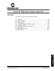
<strong>Section</strong> <strong>29.</strong> <strong>Real</strong>-<strong>Time</strong> <strong>Clock</strong> <strong>and</strong> <strong>Calendar</strong> (<strong>RTCC</strong>)<strong>29.</strong>3 <strong>RTCC</strong> OPERATIONThe <strong>RTCC</strong> module is intended to be clocked by an external real-time clock crystal oscillating at32.768 kHz. The prescaler divides the crystal oscillator frequency to produce the 1 Hz updatefrequency for the clock <strong>and</strong> calendar. The current date <strong>and</strong> time is tracked using a 7-byte counterregister that is updated once per second.Each counter counts in BCD because it allows easy conversion to decimal digits for displayingor printing. The count sequence of the individual byte counters is illustrated in Figure 29-2. Notethat the day of month <strong>and</strong> month counters roll over to one. All other counters roll over to zero.The number of days in a month <strong>and</strong> corrections for leap year are automatically adjusted. It is validup to 2100 years. Upon initial application of power, the counters contain r<strong>and</strong>om information.Figure 29-2:<strong>RTCC</strong> <strong>Time</strong>rPrescalerSOSCO32.768 kHz÷ 163842 Hz÷ 21 HzLPOSCENHALFSECSOSCI<strong>RTCC</strong> <strong>Time</strong>rYEAR(0-99)MONTH(1-12)DATE(1-28/29/30/31)WEEKDAY(0-6)HOUR(0-23)MINUTES(0-59)SECONDS(0-59)Note:The Secondary Oscillator Enable bit (LPOSCEN) in the Oscillator Control register(OSCCON) is set to allow the <strong>RTCC</strong> module to be clocked by the SOSC. Formore details, refer to <strong>Section</strong> 7. “Oscillator” (DS70580) in the “dsPIC33E/PIC24EFamily Reference Manual”.<strong>29.</strong>3.1 Writing to the <strong>RTCC</strong> <strong>Time</strong>rThe user application can configure the time <strong>and</strong> calendar by writing the desired seconds,minutes, hours, weekday, date, month <strong>and</strong> year to the <strong>RTCC</strong> registers. Under normal operation,writes to the <strong>RTCC</strong> Value registers are not allowed. Attempted writes will appear to executenormally, but the contents of the registers will remain unchanged. To write to the <strong>RTCC</strong> Valueregister, the RTCWREN bit (RCFGCAL) must be set. Setting the RTCWREN bit allowswrites to the <strong>RTCC</strong> registers. Conversely, clearing the RTCWREN bit prevents writes.The RTCWREN bit can be cleared at any time. To set the RTCWREN bit, follow these steps:1. Write 0x55 to NVMKEY.2. Write 0xAA to NVMKEY.3. Set the RTCWREN bit using a single cycle instruction.The <strong>RTCC</strong> module is enabled by setting the RTCEN bit (RCFGCAL). To set or clear theRTCEN bit, the RTCWREN bit (RCFGCAL) must be set.If the entire clock (hours, minutes <strong>and</strong> seconds) needs to be corrected, it is recommended thatthe <strong>RTCC</strong> module be disabled to avoid coincidental write operation when the timer increments.This prevents the clock from counting during a write to the <strong>RTCC</strong> Value register.29<strong>Real</strong>-<strong>Time</strong> <strong>Clock</strong><strong>and</strong> <strong>Calendar</strong>(<strong>RTCC</strong>)© 2010 <strong>Microchip</strong> Technology Inc. DS70584B-page 29-11
dsPIC33E/PIC24E Family Reference ManualIf just a single location requires modification, such as hours, minutes or seconds, the clock shouldnot be stopped. (For example, a single field is modified to correct for daylight savings time.)Stopping the clock to modify a single location introduces an error in the timekeeping. In addition,a write to the minutes or seconds register resets the prescaler.To write to the clock on-the-fly, the user application should wait until the RTCSYNC bit(RCFGCAL) is cleared before writing to the timekeeping registers. The RTCSYNC bit is setto 32 clock edges (~1 ms) before a rollover is about to occur in the prescaler. Example 29-1provides a sample code sequence to write to a <strong>RTCC</strong> timekeeping register.Example 29-1: <strong>RTCC</strong> <strong>Time</strong>keeping Register Write Operation;**********************************************; Enable <strong>RTCC</strong> <strong>Time</strong>r Access;**********************************************MOV #0x55,W0MOV W0, NVMKEYMOV #0xAA,W0MOV W0, NVMKEYBSET RCFGCAL,#RTCWREN ; Set RTCWREN bit;**********************************************; Disable the <strong>RTCC</strong> module;**********************************************BCLR RCFGCAL,#RTCEN; ; Clear RTCEN bit;**********************************************; Write to <strong>RTCC</strong> <strong>Time</strong>r;**********************************************MOV RCFGCAL,w0OR #0x300,w0MOV w0,RCFGCAL ; Set RTCPTR to 3MOV #0x0007,w0 ; Set Year (#0x00YY)MOV #0x1028,w1 ; Set Month <strong>and</strong> Day (#0xMMDD)MOV #0x0110,w2 ; Set Weekday <strong>and</strong> Hour (#0x0WHH)MOV #0x0000,w3 ; Set Minute <strong>and</strong> Second (#0xMMSS)MOVMOVMOVMOVw0,RTCVALw1,RTCVALw2,RTCVALw3,RTCVAL;**********************************************; Enable the <strong>RTCC</strong> module;**********************************************BSET RCFGCAL,#RTCEN ; Set RTCEN bit;**********************************************; Disable <strong>RTCC</strong> <strong>Time</strong>r Access;**********************************************BCLR RCFGCAL,#RTCWREN ; Clear RTCWREN bitNote:The alarm must be disabled (ALRMEN = 0) while writing to real-time clock registers,otherwise a false alarm could be generated.DS70584B-page 29-12© 2010 <strong>Microchip</strong> Technology Inc.
<strong>Section</strong> <strong>29.</strong> <strong>Real</strong>-<strong>Time</strong> <strong>Clock</strong> <strong>and</strong> <strong>Calendar</strong> (<strong>RTCC</strong>)<strong>29.</strong>3.2 Reading the <strong>RTCC</strong> <strong>Time</strong>rThe time <strong>and</strong> calendar information is obtained by reading the appropriate register bytes. The<strong>RTCC</strong> timer is read on-the-fly. To read the current time, the <strong>RTCC</strong> timer should not be stopped.Doing so would introduce an error in its timekeeping.As clocking of the counter occurs asynchronously to the reading of the counter, it is possible toread the counter while it is being incremented (rollover). This may result in an incorrect timereading. Therefore, to ensure a correct reading of the entire contents of the clock (or that part ofinterest), it must be read without a clock rollover occurring.To read the clock on-the-fly, the user application should wait until the RTCSYNC bit(RCFGCAL) becomes ‘0’, <strong>and</strong> then read the timekeeping registers. The RTCSYNC bit isset to 32 clock edges (~1 ms) before a rollover is about to occur in the prescaler.If the user application cannot wait for the RTCSYNC bit to become ‘0’, the alternate method is toread the timekeeping registers twice. If the data is same both the times, it is considered to bevalid. In that case, a minimum of two <strong>and</strong> a maximum of three accesses are required.Example 29-2 provides a sample code sequence to read a <strong>RTCC</strong> timekeeping register.Example 29-2: <strong>RTCC</strong> <strong>Time</strong>keeping Register Read Operation;**********************************************; Wait for the RTCSYNC bit to become ‘0’;**********************************************while(RCFGCALbits.RTCSYNC == 1);;**********************************************; Read the <strong>RTCC</strong> timekeeping register;**********************************************RCFGCALbits.RTCPTR = 3;year = RTCVAL;month_date = RTCVAL;wday_hour = RTCVAL;min_sec = RTCVAL;29<strong>Real</strong>-<strong>Time</strong> <strong>Clock</strong><strong>and</strong> <strong>Calendar</strong>(<strong>RTCC</strong>)© 2010 <strong>Microchip</strong> Technology Inc. DS70584B-page 29-13
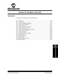
dsPIC33E/PIC24E Family Reference Manual<strong>29.</strong>4 <strong>RTCC</strong> ALARMAlarms are available to interrupt the CPU at a particular time or at periodic time intervals, suchas once per minute or once per day. During each clock update, the <strong>RTCC</strong> compares the selectedalarm registers with the corresponding clock registers. When a match occurs, an alarm event isgenerated.The Alarm Mask bits (AMASK) in the Alarm Configuration register (ALCFGRPT)are used to mask registers that do not have to be compared. Figure 29-3 illustrates the alarmBCD register nibbles that are compared with the timekeeping register for different AMASKsettings.Figure 29-3:<strong>RTCC</strong> Alarm<strong>RTCC</strong> <strong>Time</strong>rYEARMONTHDATEDAYHOURMINSEC1HzRTCOEToggle10<strong>RTCC</strong> Pin<strong>RTCC</strong> AlarmRTSECSELSet RTCIF FlagMONTHDATEDAYHOURMINSECAMASK00000001Every Half SecondEvery Second0010Every 10 Seconds0011Every Minute0100Every 10 Minutes0101Every Hour0110Every Day0111Every Week1000Every Month1001Every YearDS70584B-page 29-14© 2010 <strong>Microchip</strong> Technology Inc.
<strong>Section</strong> <strong>29.</strong> <strong>Real</strong>-<strong>Time</strong> <strong>Clock</strong> <strong>and</strong> <strong>Calendar</strong> (<strong>RTCC</strong>)For example, if you want to set an alarm for each morning at six o’clock (06:00:00 in 24-hourformat), perform the following procedure:1. In the Alarm Value register (ALRMVAL), load the hours byte with 06 (BCD), the minutesbyte with 00 (BCD), <strong>and</strong> the seconds byte with 00 (BCD).2. Mask off the month, date <strong>and</strong> weekday bytes <strong>and</strong> just compare hour, minute <strong>and</strong> secondby setting the addressing mask bits (AMASK) to ’0b0110. Each day when the time rollsover from 05:59:59, an alarm event is generated.Note:The alarm must be disabled (ALRMEN = 0) in the Alarm Configuration register(ALCFGRPT) while writing to ALRMVAL, otherwise it may result in a false alarm.ALRMVAL can be read at any time.Example 29-3 provides a sample code sequence to configure the Alarm registers to generate analarm every morning at six o’clock.Example 29-3: Writing to Alarm Register;******************************************************; Disable the Alarm;******************************************************ALCFGRPTbits.ALRMEN = 0;;******************************************************; Write to the Alarm Register (<strong>Time</strong>: 06:00:00);******************************************************ALCFGRPTbits.ALRMPTR = 2;ALRMVAL = 0x0000;ALRMVAL = 0x0006;ALRMVAL = 0x0000;;******************************************************; Select Alarm Mask to compare hour, minute <strong>and</strong> second;******************************************************ALCFGRPTbits.AMASK = 0b0110;;******************************************************; Enable the Alarm;******************************************************ALCFGRPTbits.CHIME = 1;ALCFGRPTbits.ALRMEN = 1;<strong>29.</strong>4.1 Alarm Mode SelectionThe alarm is enabled using the ALRMEN bit (ALCFGRPT), which can generate a one-timealarm <strong>and</strong> a recurring alarm.<strong>29.</strong>4.1.1 ONE-TIME ALARMThis alarm event is generated when the clock matches the selected alarm nibbles. The alarm isautomatically disabled on an alarm event. Complete the following steps to configure a one-timealarm:1. Clear the Chime Enable bit (CHIME) in the Alarm Configuration register(ALCFGRPT).2. Set the Alarm Repeat Counter Value bits (ARPT) to ‘0’.29<strong>Real</strong>-<strong>Time</strong> <strong>Clock</strong><strong>and</strong> <strong>Calendar</strong>(<strong>RTCC</strong>)<strong>29.</strong>4.1.2 CHIME DISABLEWhen CHIME = 0, the Alarm Repeat Counter Value bits (ARPT) are decremented on everyalarm event, <strong>and</strong> the alarm is disabled when the repeat counter becomes zero.<strong>29.</strong>4.1.3 CHIME ENABLEIndefinite repetition of the alarm can occur if the Chime Enable bit (CHIME) is set. WhenCHIME = 1, the Alarm Repeat Counter Value bits (APRT) in the ALCFGRPT register aredecremented indefinitely each time the alarm is issued.© 2010 <strong>Microchip</strong> Technology Inc. DS70584B-page 29-15
dsPIC33E/PIC24E Family Reference Manual<strong>29.</strong>4.2 Alarm Interrupt <strong>and</strong> OutputThe alarm event can generate an <strong>RTCC</strong> interrupt or toggle the <strong>RTCC</strong> output pin. An <strong>RTCC</strong>interrupt is enabled using the respective <strong>RTCC</strong> Interrupt Enable bit (RTCIE). The InterruptPriority Level bits (RTCIP) must be written with a non-zero value for the <strong>RTCC</strong> to be asource of interrupts. For more details, refer to <strong>Section</strong> 6. “Interrupts” (DS70600) in the“dsPIC33E/PIC24E Family Reference Manual”.In addition, an alarm event can toggle the <strong>RTCC</strong> pin, thereby generating a periodic clock at half thealarm rate. The <strong>RTCC</strong> pin is also capable of outputting the seconds clock. The user application canselect between the alarm output or the seconds clock output using the RTSECSEL bit(PADCFG1). When RTSECSEL = 0, the alarm toggles the pin on every alarm event. WhenRTSECSEL = 1, the seconds clock is selected.DS70584B-page 29-16© 2010 <strong>Microchip</strong> Technology Inc.
<strong>Section</strong> <strong>29.</strong> <strong>Real</strong>-<strong>Time</strong> <strong>Clock</strong> <strong>and</strong> <strong>Calendar</strong> (<strong>RTCC</strong>)<strong>29.</strong>5 <strong>RTCC</strong> CALIBRATIONCalibration is provided to compensate for the nominal crystal frequency <strong>and</strong> for variations in theexternal crystal frequency over a temperature range. Calibration is accomplished by adding orsubtracting counts every one minute. Adding counts speeds up the clock <strong>and</strong> subtracting countsslows the clock. The number of pulses blanked (subtracted for negative calibration) or inserted(added for positive calibration) is set by the 8-bit signed value loaded into the <strong>RTCC</strong> DriftCalibration bits (CAL) in the <strong>RTCC</strong> Configuration <strong>and</strong> Calibration Control register(RCFGCAL).Each calibration step either adds four or subtracts four oscillator cycles for every one minute(60 x 32.768 kHz = 1,966,080 oscillator cycles). This equates to ±2.034 parts per million (ppm)of adjustment per calibration step or ±5.35 seconds per month, allowing calibration of thetimekeeping accuracy within three seconds per month.Table 29-3 provides the details of the amount of adjustment for each value in the calibrationregister.Table 29-3:CalibrationValue(CAL)Calibration Adjustment ValuesAdjustmentAccuracy(ppm)<strong>Time</strong>(sec/month)CalibrationValue(CAL)AdjustmentAccuracy(ppm)<strong>Time</strong>(sec/month)0 0 — -1 -2.03 -5.271 2.03 5.27 -2 -4.07 -10.552 4.07 10.55 -3 -6.1 -15.823 6.1 15.82 -4 -8.14 -21.09•••••••••125 254.31 659.18 -126 -256.35 -664.45126 256.35 664.45 -127 -258.38 -669.73127 258.38 669.73 -128 -260.42 -675•••••••••To establish the degree of calibration needed in a given application, the following method, whichis specially suited to manufacturing environments, can be used:1. Output the seconds clock (1 Hz) on the <strong>RTCC</strong> pin, measure the crystal oscillatorfrequency, <strong>and</strong> calculate the crystal frequency deviation in Hz.2. Frequency Error = 32.768 kHz – Measured Frequency.3. Calculate counter error per minute due to frequency deviation.Count Error = (Frequency Error) x 60.4. Set the CAL bits to (Count Error/4).Note:The user application can use a temperature sensor to adjust the calibration value tocompensate for the temperature drift.29<strong>Real</strong>-<strong>Time</strong> <strong>Clock</strong><strong>and</strong> <strong>Calendar</strong>(<strong>RTCC</strong>)© 2010 <strong>Microchip</strong> Technology Inc. DS70584B-page 29-17
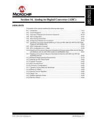
dsPIC33E/PIC24E Family Reference Manual<strong>29.</strong>5.1 Writing the Calibration ValueThe <strong>RTCC</strong> module performs calibration or adjusts the prescaler for every minute(see Figure 29-4). The calibration point is at the 512th clock edge following the seconds BCDcounter rollover (59 to 00).Figure 29-4:Calibration Point1 second = 32768 <strong>RTCC</strong> clock cycles32767PrescalerCounterCalibration point512 <strong>RTCC</strong> cycles32 <strong>RTCC</strong> clockRTCSYNCHALFSECSECONDS 59 0 1MINUTES 12At the calibration point, the <strong>RTCC</strong> module reads the 8-bit signed value (CAL) <strong>and</strong> adjuststhe prescaler counter accordingly. When the <strong>RTCC</strong> module reads the value, it should not beupdated by the CPU; thereby ensuring that the <strong>RTCC</strong> module reads the correct calibration value.When the seconds byte is zero <strong>and</strong> the HALFSEC bit (RCFGCAL) becomes ‘1’, thecalibration value must be updated.Example 29-4 provides a sample code sequence to update the calibration value on-the-fly.Example 29-4: Writing the Calibration Value;***************************************************************; Read the <strong>RTCC</strong> timer to check the seconds; If the seconds byte is 0, wait for the HALFSEC bit to become 1;***************************************************************RCFGCALbits.RTCPTR = 0;seconds = (RTCVAL & 0xFF);if(seconds == 0)while(RCFGCALbits.HALFSEC == 0);;**************************************************************; Write to the calibration value;**************************************************************RCFGCALbits.CAL = calvalue;DS70584B-page 29-18© 2010 <strong>Microchip</strong> Technology Inc.
<strong>Section</strong> <strong>29.</strong> <strong>Real</strong>-<strong>Time</strong> <strong>Clock</strong> <strong>and</strong> <strong>Calendar</strong> (<strong>RTCC</strong>)<strong>29.</strong>6 <strong>RTCC</strong> OPERATION IN POWER-SAVING MODES<strong>29.</strong>6.1 Sleep ModeWhen the device enters Sleep mode, the system clock is disabled. Because the <strong>RTCC</strong> timer isclocked by the secondary oscillator, it will continue to run in Sleep mode.If enabled, the alarm interrupt wakes up the device from Sleep mode <strong>and</strong> the following occurs:• If the assigned priority for the interrupt is less than, or equal to, the current CPU priority, thedevice wakes up <strong>and</strong> continues code execution from the instruction following the PWRSAVinstruction that initiated Sleep mode.• If the assigned priority level for the interrupt source is greater than the current CPU priority,the device wakes up <strong>and</strong> the CPU exception process begins. Code execution continuesfrom the first instruction of the timer Interrupt Service Routine (ISR).For more details on power-saving modes, refer to <strong>Section</strong> 9. “Watchdog <strong>Time</strong>r <strong>and</strong>Power-Saving Modes” (DS70615) in the “dsPIC33E/PIC24E Family Reference Manual”.<strong>29.</strong>6.2 Idle ModeIdle mode does not affect the operation of the <strong>RTCC</strong> module.29<strong>Real</strong>-<strong>Time</strong> <strong>Clock</strong><strong>and</strong> <strong>Calendar</strong>(<strong>RTCC</strong>)© 2010 <strong>Microchip</strong> Technology Inc. DS70584B-page 29-19
DS70584B-page 29-20 © 2010 <strong>Microchip</strong> Technology Inc.<strong>29.</strong>7 REGISTER MAPTable 29-4:A summary of the registers associated with the dsPIC33E/PIC24E <strong>RTCC</strong> module is provided in Table 29-4.<strong>RTCC</strong> Register MapFile Name Bit 15 Bit 14 Bit 13 Bit 12 Bit 11 Bit 10 Bit 9 Bit 8 Bit 7 Bit 6 Bit 5 Bit 4 Bit 3 Bit 2 Bit 1 Bit 0ALRMVAL Alarm Value Register Window based on ALRMPTR xxxxALCFGRPT ALRMEN CHIME AMASK ALRMPTR ARPT 0000RTCVAL <strong>RTCC</strong> Value Register Window based on RTCPTR xxxxRCFGCAL RTCEN — RTCWREN RTCSYNC HALFSEC RTCOE RTCPTR CAL 0000PADCFG1 — — — — — — — — — — — — — — RTSECSEL PMPTTL 0000Legend:x = unknown value on Reset, — = unimplemented, read as ‘0’. Reset values are shown in hexadecimal.AllResetsdsPIC33E/PIC24E Family Reference Manual
<strong>Section</strong> <strong>29.</strong> <strong>Real</strong>-<strong>Time</strong> <strong>Clock</strong> <strong>and</strong> <strong>Calendar</strong> (<strong>RTCC</strong>)<strong>29.</strong>8 RELATED APPLICATION NOTESThis section lists application notes that are related to this section of the manual. Theseapplication notes may not be written specifically for the dsPIC33E/PIC24E product family, but theconcepts are pertinent <strong>and</strong> could be used with modification <strong>and</strong> possible limitations. The currentapplication notes related to the <strong>RTCC</strong> module are:Title Application Note #No related application notes at this time.Note:Please visit the <strong>Microchip</strong> web site (www.microchip.com) for additional applicationnotes <strong>and</strong> code examples for the dsPIC33E/PIC24E family of devices.29<strong>Real</strong>-<strong>Time</strong> <strong>Clock</strong><strong>and</strong> <strong>Calendar</strong>(<strong>RTCC</strong>)© 2010 <strong>Microchip</strong> Technology Inc. DS70584B-page 29-21
dsPIC33E/PIC24E Family Reference Manual<strong>29.</strong>9 REVISION HISTORYRevision A (September 2009)This is the initial released version of this document.Revision B (June 2010)This revision includes the following changes:• Deleted the watermark “Untested Code – For Information Purposes Only” from the codeexamples• Minor changes to the text <strong>and</strong> formatting have been incorporated throughout the documentDS70584B-page 29-22© 2010 <strong>Microchip</strong> Technology Inc.
Note the following details of the code protection feature on <strong>Microchip</strong> devices:• <strong>Microchip</strong> products meet the specification contained in their particular <strong>Microchip</strong> Data Sheet.• <strong>Microchip</strong> believes that its family of products is one of the most secure families of its kind on the market today, when used in theintended manner <strong>and</strong> under normal conditions.• There are dishonest <strong>and</strong> possibly illegal methods used to breach the code protection feature. All of these methods, to ourknowledge, require using the <strong>Microchip</strong> products in a manner outside the operating specifications contained in <strong>Microchip</strong>’s DataSheets. Most likely, the person doing so is engaged in theft of intellectual property.• <strong>Microchip</strong> is willing to work with the customer who is concerned about the integrity of their code.• Neither <strong>Microchip</strong> nor any other semiconductor manufacturer can guarantee the security of their code. Code protection does notmean that we are guaranteeing the product as “unbreakable.”Code protection is constantly evolving. We at <strong>Microchip</strong> are committed to continuously improving the code protection features of ourproducts. Attempts to break <strong>Microchip</strong>’s code protection feature may be a violation of the Digital Millennium Copyright Act. If such actsallow unauthorized access to your software or other copyrighted work, you may have a right to sue for relief under that Act.Information contained in this publication regarding deviceapplications <strong>and</strong> the like is provided only for your convenience<strong>and</strong> may be superseded by updates. It is your responsibility toensure that your application meets with your specifications.MICROCHIP MAKES NO REPRESENTATIONS ORWARRANTIES OF ANY KIND WHETHER EXPRESS ORIMPLIED, WRITTEN OR ORAL, STATUTORY OROTHERWISE, RELATED TO THE INFORMATION,INCLUDING BUT NOT LIMITED TO ITS CONDITION,QUALITY, PERFORMANCE, MERCHANTABILITY ORFITNESS FOR PURPOSE. <strong>Microchip</strong> disclaims all liabilityarising from this information <strong>and</strong> its use. Use of <strong>Microchip</strong>devices in life support <strong>and</strong>/or safety applications is entirely atthe buyer’s risk, <strong>and</strong> the buyer agrees to defend, indemnify <strong>and</strong>hold harmless <strong>Microchip</strong> from any <strong>and</strong> all damages, claims,suits, or expenses resulting from such use. No licenses areconveyed, implicitly or otherwise, under any <strong>Microchip</strong>intellectual property rights.TrademarksThe <strong>Microchip</strong> name <strong>and</strong> logo, the <strong>Microchip</strong> logo, dsPIC,KEELOQ, KEELOQ logo, MPLAB, PIC, PICmicro, PICSTART,PIC 32 logo, rfPIC <strong>and</strong> UNI/O are registered trademarks of<strong>Microchip</strong> Technology Incorporated in the U.S.A. <strong>and</strong> othercountries.FilterLab, Hampshire, HI-TECH C, Linear Active Thermistor,MXDEV, MXLAB, SEEVAL <strong>and</strong> The Embedded ControlSolutions Company are registered trademarks of <strong>Microchip</strong>Technology Incorporated in the U.S.A.Analog-for-the-Digital Age, Application Maestro, CodeGuard,dsPICDEM, dsPICDEM.net, dsPICworks, dsSPEAK, ECAN,ECONOMONITOR, FanSense, HI-TIDE, In-Circuit SerialProgramming, ICSP, Mindi, MiWi, MPASM, MPLAB Certifiedlogo, MPLIB, MPLINK, mTouch, Octopus, Omniscient CodeGeneration, PICC, PICC-18, PICDEM, PICDEM.net, PICkit,PICtail, REAL ICE, rfLAB, Select Mode, Total Endurance,TSHARC, UniWinDriver, WiperLock <strong>and</strong> ZENA aretrademarks of <strong>Microchip</strong> Technology Incorporated in theU.S.A. <strong>and</strong> other countries.SQTP is a service mark of <strong>Microchip</strong> Technology Incorporatedin the U.S.A.All other trademarks mentioned herein are property of theirrespective companies.© 2010, <strong>Microchip</strong> Technology Incorporated, Printed in theU.S.A., All Rights Reserved.Printed on recycled paper.ISBN: 978-1-60932-288-5<strong>Microchip</strong> received ISO/TS-16949:2002 certification for its worldwideheadquarters, design <strong>and</strong> wafer fabrication facilities in Ch<strong>and</strong>ler <strong>and</strong>Tempe, Arizona; Gresham, Oregon <strong>and</strong> design centers in California<strong>and</strong> India. The Company’s quality system processes <strong>and</strong> proceduresare for its PIC ® MCUs <strong>and</strong> dsPIC ® DSCs, KEELOQ ® code hoppingdevices, Serial EEPROMs, microperipherals, nonvolatile memory <strong>and</strong>analog products. In addition, <strong>Microchip</strong>’s quality system for the design<strong>and</strong> manufacture of development systems is ISO 9001:2000 certified.© 2010 <strong>Microchip</strong> Technology Inc. DS70584B-page 23
Worldwide Sales <strong>and</strong> ServiceAMERICASCorporate Office2355 West Ch<strong>and</strong>ler Blvd.Ch<strong>and</strong>ler, AZ 85224-6199Tel: 480-792-7200Fax: 480-792-7277Technical Support:http://support.microchip.comWeb Address:www.microchip.comAtlantaDuluth, GATel: 678-957-9614Fax: 678-957-1455BostonWestborough, MATel: 774-760-0087Fax: 774-760-0088ChicagoItasca, ILTel: 630-285-0071Fax: 630-285-0075Clevel<strong>and</strong>Independence, OHTel: 216-447-0464Fax: 216-447-0643DallasAddison, TXTel: 972-818-7423Fax: 972-818-2924DetroitFarmington Hills, MITel: 248-538-2250Fax: 248-538-2260KokomoKokomo, INTel: 765-864-8360Fax: 765-864-8387Los AngelesMission Viejo, CATel: 949-462-9523Fax: 949-462-9608Santa ClaraSanta Clara, CATel: 408-961-6444Fax: 408-961-6445TorontoMississauga, Ontario,CanadaTel: 905-673-0699Fax: 905-673-6509ASIA/PACIFICAsia Pacific OfficeSuites 3707-14, 37th FloorTower 6, The GatewayHarbour City, KowloonHong KongTel: 852-2401-1200Fax: 852-2401-3431Australia - SydneyTel: 61-2-9868-6733Fax: 61-2-9868-6755China - BeijingTel: 86-10-8528-2100Fax: 86-10-8528-2104China - ChengduTel: 86-28-8665-5511Fax: 86-28-8665-7889China - ChongqingTel: 86-23-8980-9588Fax: 86-23-8980-9500China - Hong Kong SARTel: 852-2401-1200Fax: 852-2401-3431China - NanjingTel: 86-25-8473-2460Fax: 86-25-8473-2470China - QingdaoTel: 86-532-8502-7355Fax: 86-532-8502-7205China - ShanghaiTel: 86-21-5407-5533Fax: 86-21-5407-5066China - ShenyangTel: 86-24-2334-2829Fax: 86-24-2334-2393China - ShenzhenTel: 86-755-8203-2660Fax: 86-755-8203-1760China - WuhanTel: 86-27-5980-5300Fax: 86-27-5980-5118China - XianTel: 86-29-8833-7252Fax: 86-29-8833-7256China - XiamenTel: 86-592-2388138Fax: 86-592-2388130China - ZhuhaiTel: 86-756-3210040Fax: 86-756-3210049ASIA/PACIFICIndia - BangaloreTel: 91-80-3090-4444Fax: 91-80-3090-4123India - New DelhiTel: 91-11-4160-8631Fax: 91-11-4160-8632India - PuneTel: 91-20-2566-1512Fax: 91-20-2566-1513Japan - YokohamaTel: 81-45-471- 6166Fax: 81-45-471-6122Korea - DaeguTel: 82-53-744-4301Fax: 82-53-744-4302Korea - SeoulTel: 82-2-554-7200Fax: 82-2-558-5932 or82-2-558-5934Malaysia - Kuala LumpurTel: 60-3-6201-9857Fax: 60-3-6201-9859Malaysia - PenangTel: 60-4-227-8870Fax: 60-4-227-4068Philippines - ManilaTel: 63-2-634-9065Fax: 63-2-634-9069SingaporeTel: 65-6334-8870Fax: 65-6334-8850Taiwan - Hsin ChuTel: 886-3-6578-300Fax: 886-3-6578-370Taiwan - KaohsiungTel: 886-7-536-4818Fax: 886-7-536-4803Taiwan - TaipeiTel: 886-2-2500-6610Fax: 886-2-2508-0102Thail<strong>and</strong> - BangkokTel: 66-2-694-1351Fax: 66-2-694-1350EUROPEAustria - WelsTel: 43-7242-2244-39Fax: 43-7242-2244-393Denmark - CopenhagenTel: 45-4450-2828Fax: 45-4485-2829France - ParisTel: 33-1-69-53-63-20Fax: 33-1-69-30-90-79Germany - MunichTel: 49-89-627-144-0Fax: 49-89-627-144-44Italy - MilanTel: 39-0331-742611Fax: 39-0331-466781Netherl<strong>and</strong>s - DrunenTel: 31-416-690399Fax: 31-416-690340Spain - MadridTel: 34-91-708-08-90Fax: 34-91-708-08-91UK - WokinghamTel: 44-118-921-5869Fax: 44-118-921-582001/05/10DS70584B-page 24© 2010 <strong>Microchip</strong> Technology Inc.