Powerpoint - City University of Hong Kong
Powerpoint - City University of Hong Kong
Powerpoint - City University of Hong Kong

You also want an ePaper? Increase the reach of your titles
YUMPU automatically turns print PDFs into web optimized ePapers that Google loves.
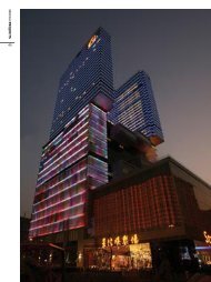
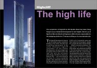
Redevelopment <strong>of</strong> the Lee GardensHotel – The Manulife Tower
Redevelopment <strong>of</strong> the Hilton Hotel –Cheung <strong>Kong</strong> Center
International Finance Center Tower 2
International Finance Center Tower 1 – RC core + RC perimeter columns configurationup to 23/F, 23/F to 38/F becomes a composite structure with columns & slabs in steel
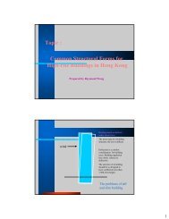
Characteristic for buildings constructed in compositemanner in <strong>Hong</strong> <strong>Kong</strong>• Size <strong>of</strong> building usually very large – floor area ranging from1800 to 2500 sq m, total floor area from 80000 to 200000 sq m• Structural forms bear similarity – RC core as the inner tubeprovide rigidity, external frame with perimeter steelcolumns/edge beams, floor in composite deck with RC topping• Very few columns provided at base/lower level to createspacious lobby at Ground entrance• External bracing members are seldom used to avoid blocking<strong>of</strong> valuable exterior view. Belt truss and outrigger systems areused instead• Buildings usually consist <strong>of</strong> a very large and deep basement
IFC 2 – structural configuration <strong>of</strong> thetower with the first set <strong>of</strong> Transfer/BeltTruss on 6/F, mega-columns, edgebeams, floor deck. and the RC core
Connecting the steel frame tothe inner core as seen in theCheung <strong>Kong</strong> Center
External bracingDiagonal bracing on external wallseldom used in <strong>Hong</strong> <strong>Kong</strong>’sbuilding. The one as seen here isthe Shenzhen Shun Hing Plaza
A 5-level basement wasconstructed using topdownarrangement at thesame time together withthe IFC2 superstructure
Similar situation <strong>of</strong>construction a deepbasement using topdownarrangementalso appeared in theCheung <strong>Kong</strong>Center project
Major elements in Composite Building StructuresCore wall• Serves as the major load taking element and to providerigidity to resist deflection caused by lateral load (wind)• Usually formed by mechanical-lifted formwork systemsuch as climb form or jump form• Connection provision such as anchor plate for steel beams,build-in bar couplers or starter bar box for slab, andanchor frame for outrigger, will be provided in the corewall during its construction
Systematics and ClassificationMonophyletic Group29Systematics and ClassificationParaphyletic Group3015
Manulife TowerForming the core wall usingtraditional timber formworkinside the basement levels
Climb form system for theconstruction <strong>of</strong> the core wall for theManulift Tower’s superstructure
International Finance CenterTower 2Climb form system for theconstruction <strong>of</strong> the core wall for theInternational Finance Center Tower 2
Anchor frame and connecting plateembedded in the core wall for furtherconnection to the external steel frame
Anchor frame used in the Shun Hing Square project in Shenzhen
Work deck <strong>of</strong> theClimb-form systemConnectingplate for steelfloor beamsStarter bar boxConnection arrangement provided in the core wall
Another view <strong>of</strong> the connection arrangement at the core wall cornerStarterbar box
Major elements in Composite Building StructuresStructural steel external frame• Composing <strong>of</strong> steel columns that tied onto the core wallby steel beams• Steel columns can be- in the form <strong>of</strong> H-section, square, rectangular orcircular section- in-fill with lightweight concrete to increase rigidityand fire resistance- in the form <strong>of</strong> composite with reinforcing steel barsencased with load-taking reinforced concrete- in the form <strong>of</strong> concrete-filled column design
Concrete filled steel column used inCheung <strong>Kong</strong> Center
Square sectioned columnsInlet forconcrete infill
Various forms <strong>of</strong> composite columns
Composite column composing <strong>of</strong>thick fabricated steel section andencased with reinforced concrete
Composite columns forming themega-column for the IFC2
Composite columnencased with RCComposite column composing<strong>of</strong> H-section sub-stanchion
External steel column being erected & tied back onto core wall by steel beams
Connecting steel beams ontothe core wallBeams weld or boltconnectedonto the gussetplate anchored firmly intothe anchor palte/framewithin the core wall
Major elements in Composite Building StructuresFloor plate• Usually in the form <strong>of</strong> RC topping composite to steelbeams by shear studs• GI corrugated decking used as permanent form for theplacing <strong>of</strong> the RC topping• Floor plate is connected to the core wall by starter barsembedded in the core wall
Placing the steel deckonto the steel beams
Detail <strong>of</strong> the slab (beforeconcreting) with steel barsand shear stud to allow theforming <strong>of</strong> a firmcomposite with the beams
Starter barsConnecting composite slabwith the core wall and thecolumn using starter bars
Welding the shear stud ontothe steel joist to enable thefloor slab to form firmcomposite with the beams
Placing concrete to form the RC topping <strong>of</strong> the composite slab
Major elements in Composite Building StructuresTransfer truss• Common design in <strong>Hong</strong> <strong>Kong</strong> to provide a spaciousground lobby to a building by using the minimumnumber <strong>of</strong> columns at the lower floors to support theentire superstructure• Transfer truss is used to transfer the building loads fromthe upper columns down onto the main columns at lowerlevel• Transfer truss sometimes connected to the outrigger toincrease the rigidity <strong>of</strong> the building at lower levels
The arrangement <strong>of</strong> theTransfer Truss for theManulife Tower
Detail <strong>of</strong> the Transfer Truss located at3/F-4/F for the Cheung <strong>Kong</strong> Center
Erecting the transfer truss system –temporary support frame to be provided forinstalling the large-section truss members
Elevation and InstallationArrangement for the TransferTruss <strong>of</strong> Cheung <strong>Kong</strong> Center
Transfer Truss located at 6/F-8/F for theInternational Finance Center Tower 2
Construction zonefor core wallCore wall and buildingframe lapping zoneBuilding frameerection zone6/F-8/FTransfer TrussOverall structural/constructionarrangement <strong>of</strong> the IFC 2
Major elements in Composite Building StructuresBelt truss and Outrigger• Provided to building frame at interval every 20 to 25floors to allow building to regain its stiffness.• Often in the form <strong>of</strong> inclined bracing, stretching inward,outward or in “X” or “Y” configuration• An anchor frame is embedded in the core for connectingthe outrigger in order to cater for the strong pulling outtendency
Belt truss and outrigger systems<strong>of</strong> Cheung <strong>Kong</strong> Center
Layout detail <strong>of</strong> the belt truss andoutrigger systems <strong>of</strong> Cheung <strong>Kong</strong> Center
Outrigger and the column connection detail
Overview <strong>of</strong> the belt truss systemCheung <strong>Kong</strong> Center
Installation <strong>of</strong> the belt truss atcarefully arranged sequence
Elevation detail <strong>of</strong> thecompleted outrigger andbelt truss system
Installation <strong>of</strong>the belt trussInternational Finance Center 2
Corner steel postembedded in the core wallOutriggerCompositecolumnThe outrigger connecting into the core wall in IFC 2
Installing the bracing frame for the outrigger using a retro-installation process –core wall cast in 2 phases with the bracing frame installed in between
Corner steel postembedded in the core wallEmbedding the anchor frame into the core wall
Sequential detail <strong>of</strong> theretro-installation process <strong>of</strong>casting the bracing frameinto the core wall
Connection detail <strong>of</strong> the outriggerand the mega-column – a devicesto control differential shorteningbetween the steel column and theRC core wall is introduced
Detail <strong>of</strong> the column shortening controldevices with the use <strong>of</strong> shimming packadjusted by hydraulic action
Similar column shortening controldevices was also provided in theCheung <strong>Kong</strong> Center’s design
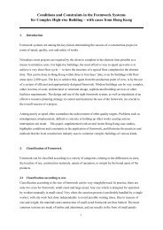
Production concerns for the construction <strong>of</strong>composite structureThe construction <strong>of</strong> composite structures in <strong>Hong</strong> <strong>Kong</strong> is verycomplicated in terms <strong>of</strong> their size and work nature. Thefollowings are some <strong>of</strong> the common problems <strong>of</strong>tenencountered.1. Site layout to cater for very congested site environment2. Simultaneous works3. Cranage requirements4. Provision <strong>of</strong> temporary work arrangement during construction5. Height and headroom problems6. Works at peak period7. Controlling <strong>of</strong> rain water during construction
Extremely complicated site layout during the construction – demolition <strong>of</strong> theold basement, foundation works, forming <strong>of</strong> the building core, erection <strong>of</strong> steelcolumn and constructing the ground slab worked almost at the same timeLee Garden Hotel redevelopment
Layout situation during the later stage <strong>of</strong> basement formation period
Layout situation during the ground slab formation and corewall construction period
Layout situation during the constructionperiod for the superstructure and thetop-down basement
Foundation for Hotel block andbasement access arrangementhad just commencedPodium and basementbelow was partiallycompletedConstruction <strong>of</strong> thesuperstructure up tothe typical cycleLayout arrangement for the IFC2 at its peakIFC 2
Layout as shown 4 months later
Working and handling <strong>of</strong>material at height
Core wall and steelframe worked atdifferent phases –A lapse <strong>of</strong> sometimesmore than 10 floorsmake access to thedeck level <strong>of</strong> the corewall very difficult
Temporary access provision inside the core wall
Delivery and lifting<strong>of</strong> steel members
Handling <strong>of</strong> very heavyfabricated components
Provision <strong>of</strong> lifting equipment forthe hoisting <strong>of</strong> heavy steelmembers as seen in “The Center”and “Manulife Tower” projects
Cranage provision in Cheung <strong>Kong</strong>Center – 2 luffing cranes with600Tm capacity was provided atcorner position <strong>of</strong> the core wall
Locating the cranesinside the core wall
Cranage demandThere are altogether about 26000 steel members (averageabout 0.9 ton) being used in the Cheung <strong>Kong</strong> Center.The construction period for the building frame takes about50 weeks. That means, the cranage requirement at average isabout 520 ton/week, or about 100 ton/day, excluding thelifting <strong>of</strong> other materials such as the decking sheet or usualreinforcing bars
Temporary work provision –Erection <strong>of</strong> a temporary steeltruss for the erection <strong>of</strong> veryheavy or large span elements
Erection <strong>of</strong> temporaryscaffold to carry outwelding works (to theoutrigger system <strong>of</strong> IFC 2)
Erection <strong>of</strong> temporarysuspended platform for thefinal installation <strong>of</strong> theoverhanging steel components
Slot opening on ro<strong>of</strong>Temporary work arrangement –Formation <strong>of</strong> a slot opening in thestructure for the access <strong>of</strong> large andheavy components
Intensive use <strong>of</strong> dry wall makingwater-tightness become morecrucial in composite buildings
Fire Resisting treatment to steel incomposite/structural steel buildingsThese can be done either by• Encasing the structural steel elements with concrete• Covering the elements with fire resisting boarding(e.g. cement board)• Covering the element with fire resisting plaster(e.g. spray-on vermiculite/cement-base plaster)
Applying spray-on fireresisting plaster to exposedstructural steel members
Gate valve for theinfilling <strong>of</strong> lightweight concrete tosteel column (a wayto improveperformance <strong>of</strong> thecolumn under fire)Outrigger frame inCheung <strong>Kong</strong> Centerafter the application<strong>of</strong> fire resistingplaster material
Encasing the fire escape and lift shaftwith fire resisting board/partition
Encasing the steel beams withconcrete for fire resisting purpose
Concrete encasement to steel membersConcrete encasement is provided to steel column in order to:• Convert steel column into composite column• Increase the rigidity <strong>of</strong> the column• Make the column fire resisting
Steel column before encasedwith reinforced concrete
Encasing a column using traditionalmanual/timber formwork
Encasing a column usingsteel gang formwork
Encasing a column usingself-climbing formwork
Operation <strong>of</strong> the self-climbing formfor the composite column in IFC2
Future development <strong>of</strong> using structural steel orcomposite structures in <strong>Hong</strong> <strong>Kong</strong>Instead <strong>of</strong> building very large and complex building usingcomposite manner, which resulted to very high cost inconstruction, the following ways may be adopted in orderto achieve more cost effective application <strong>of</strong> technology infuture.1. Use more simple and straight forward design like regular steelframe structure in grid layout2. Use more standardized components such as universal sections,lattice trusses or prefabricated standard sections in the design3. Apply more to other types <strong>of</strong> building structure/construction asin many developed country like Japan, USA, or even Korea andTaiwan4. Forming hybrid structure with other prefabricated elements
The use <strong>of</strong> standard structuralsteel members in construction
Convenient products in market allowingthe use <strong>of</strong> very cheap and effectiveready-install structural steel members t<strong>of</strong>orm various building systems
A hybrid structure in Melbourne, Australia with the mixed use <strong>of</strong>Precast concrete, cast-in-situ concrete and steel composite
Detail <strong>of</strong> the hybrid elements
End <strong>of</strong> this presentation