Hammer Pocket Manual - Berminghammer Foundation Equipment
Hammer Pocket Manual - Berminghammer Foundation Equipment
Hammer Pocket Manual - Berminghammer Foundation Equipment

Create successful ePaper yourself
Turn your PDF publications into a flip-book with our unique Google optimized e-Paper software.
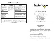
<strong>Hammer</strong> Maintenance ChartITEM FREQUENCY ACTIONIMPACT BLOCK 20 MIN. ** LUBRICATE WITH FLEX LUBE, 10SHOTS PER FITTINGFUEL & OIL PUMP 20 MIN. ** OIL WITH TK680 3 TO 4 SHOTS PERFITTINGHAMMER GIBSTRIP GIBSBEFORE DRIVING OR AS NEED-EDBEFORE DRIVING OR AS NEED-EDTorque Specifications—Socket Head Cap ScrewLUBRICATE WITH EP2 GREASE ASNEEDEDLUBRICATE WITH EP2 GREASE ASNEEDEDWASTE TANK DAILY OR AS NEEDED DRAIN AND DISPOSE OF IN ACCORD-ANCE TO LAWSREMOTE THROTTLE WEEKLY OR AS NEEDED FILL WITH DEXTRON II/III OR EQUALGREASE FITTINGS MONTHLY REMOVE AND INSPECT—CLEAN CAVI-TIES IN HAMMER AND FITTINGS AND/OR REPLACEPISTON DROP TIME MONTHLY PERFORM DROPTIME TEST TO GAGEPISTON RING WEARTRIP LINKAGE MONTHLY OR AS NEEDED LUBRICATE WITH EP2 GREASE ASNEEDEDIN-LINE FUEL FILTERS MONTHLY OR AS NEEDED REMOVE AND REPLACEFUEL CARTRIDGE FILTER MONTHLY OR AS NEEDED REMOVE AND REPLACECOMPRESSION RINGS SEMI - ANNUALLY OR AS NEED- REMOVE AND REPLACEEDCUSHION RINGS QUATERLY OR AS NEEDED INSPECT PRE-LOAD TENSION—REPLACE AS NEEDEDNOTE: ** DENOTES "RUNNING TIME"FOR FURTHER SERVICE INFORMATION REFER TO THE HAMMER MANUALSHCS Holo Krome1960 Series A574Imperial Coarse Thread Metric Coarse ThreadWith NordLock Washer Locte Only( lbs) w/oiled threads( lbs) withlocteSHCS Holo Krome 1960Series Grade 12.9With NordLock Washer Locte Only( lbs) w/oiled threads( lbs) withlocte1/4" 12 16 M8 23 315/16" 23 34 M10 47 623/8" 39 61 M12 80 1077/16" 60 99 M14 128 * 173 *1/2" 93 * 150 * M16 193 2699/16" 141 * 225 * M18 272 3685/8" 184 283 M20 379 5233/4" 321 500 M22 515 7087/8" 514 687 M24 654 8991" 776 1041 M27 949 13271 1/4" 1530 2083 M30 1298 18071 1/2" 2640 3791 M33 1742 2456M36 2251 3156M39 2894 4075* If torquing injector clamp bolts, use 36 . lbs. Alternate the ghtening of these bolts using uniform torque sothat the clamp pulls ‘straight’ on the injector body and does not introduce a ‘bending’ load – this can causepoor injector performance and excessive injector ‘drip’, and the possibility of injector or bolt failure.<strong>Hammer</strong> <strong>Pocket</strong> <strong>Manual</strong>Web Version RQBermingham <strong>Foundation</strong> SolutionsWellington Street Marine TerminalHamilton, Ontario, CanadaPh. 905-528-0425Toll-free 800-668-9432Fax. 905-528-6187www.berminghammer.com<strong>Hammer</strong> <strong>Pocket</strong> <strong>Manual</strong>This <strong>Pocket</strong> <strong>Manual</strong> is a brief summary of proper hammer operation, inspection and maintenance.Read it first, and refer to the <strong>Hammer</strong> <strong>Manual</strong> for greater detail. Consult withBermingham for any additional information needed.MaintenanceFuel – Diesel*Use a good grade of filtered #2 diesel containing a Low Sulphur Diesel Fuel Conditioner(Kleen Flo or equivalent), to ensure adequate injector lubrication. Follow the manufacturer’srecommended mix ratio.DO NOT USE STARTING FLUIDS!Lube Oil –Piston and CylinderUse any good multi-grade detergent oil (15W40). Use (5W30) oil for temperatures below –20º F. Before driving squeeze the oil primer bulb several times to prime the oil pumpNOTE: Observe the hammer piston for several minutes as it rises out of the upper cylinder- if the piston is shiny the oiling system is working properly. If the piston is not shiny, checkthe oil tank. Ensure that the tank vents & valves are open. Check to see Oil pump indicator isvisibly triggering on each stroke. Squeeze the primer bulb three times and test again. Oilpump adjustment may be necessary to provide adequate lubrication. Remove keeper, turnadjuster nut counter-clockwise, and re-install keeper. Additionally, it may be necessary torebuild the oil pump. See “Troubleshooting” in the hammer manual for more information.Re-fueling and Re-oilingEnsure that the tank vents are open. Keep all tanks full of fluid to prevent condensation fromforming. If hammer is not equipped with ground re-fueling, remove the fuel and/or oil tankplug and fill the tank with the aid of a funnel.If ground re-fueling is present, wipe the quick disconnects clean and using the quick-connectfittings supplied in the toolbox, attach the ground fueling and oiling lines. It is best to attachthese lines before the hammer is operated and becomes hot. Pump fuel and/or oil into thefitting marked “DIESEL” or “OIL” located at the bottom of the hammer.* NOTE: Biodegradable alternatives are available from <strong>Berminghammer</strong>.Lube Oil –Fuel Pump and Oil PumpThe pumps should be oiled through the lubrication fittings, using ESSO Cylesstic TK680, asper the maintenance chart.USE OIL, NOT GREASE FOR PUMPS!
GreasingOnly high temperature clay based greases can be used. Zep Flex Lube grease is approved forthis application. Apply the grease through the greasefittings located on the lower cylinder. In the servicechart it is referred to as greasing the “Impact Block”.To ensure the impact block is receiving grease, at leastmonthly remove the grease fittings and inspect the hammercavities and fittings for plugging. Clean cavitiesand fittings and/or replace as necessary (see maintenancechart).Notes:Proper lubrication of the piston and impact blockrings ensures maximum piston ring life and minimizeshammer bore wear. Piston ring wear can bemeasured by performing a Drop Time Test – see thespecial notes section of this manual.If driving batter piles for an extended period, at theend of each shift, the piston must be rotated to preventconcentrated wear on the piston. This can beaccomplished by inserting a lifting eye in the top ofpiston and rotating it or by using a piston turningtool available from Bermingham.The hammer must be sitting on a pileor drive adapter to ensure the greasefittings are aligned to the correctgreasing position. See pictorial.PILE ORGREASINGSTUMPIMPACTBLOCK<strong>Hammer</strong> Throttle Control For first of day starts, as well as “re-strikes”, two dry drops are required (with no throttleand one injector removed). For cold starts and heavy pile batters, the piston shouldbe lifted slowly with a slight pause above the exhaust port to allow impact block tosettle on the pile. Fuel/oil tank vents and shut off valves must be open. <strong>Hammer</strong>s should start around 350 PSI on the hydraulic hand pump. Lower pressuresshould be tried first. Higher pressures may be required in softer driving and/or starting6505(HD) and B64 hammers (around 450 PSI). Maximum stroke should occur between 550-600 psi. The maximum rated stroke maynot be obtainable in all driving conditions, or when the hammer heats up excessively.Fuel pump adjustment may be possible. Additionally, the throttle valve or fuel pumpmay need rebuilding. Use caution on pile “restrikes” – higher strokes may occur at lower throttle pressures.Attempt to start hammer at a lower setting. Release pressure on hand pump to shut off hammer.Emergency <strong>Hammer</strong> StopIn case the remote throttle control fails to stop hammer, lifting the hammerbody approx 6” off the pile will stop the hammer.GREASENIPPLESAny occurrence of the catch cap being struck, requires the hammer to bestopped to inspect the catch cap stop edge/ring and piston catch ring, and forany necessary remedial action to be taken. The hammer must not be run witha damaged/missing piston catch ring or chamfered/rolled/excessively sharp(cut hazard) catch cap stop edge/ring. *This is a hammer safety feature.*Service Check List Check to see that all bolts, especially gibs bolts and guide ring bolts, are tight. Inspect the hammer for cracks, (esp. the fuel guards, trip slot areas and tank areas).Contact Bermingham. Do not weld on hammer without prior consent. Check that trip safety lever roll pins are in place and secure. See pin location in partsmanual. Grease the hammer as per service chart. Maintain Oil & Fuel levels in tanks. Drain waste tank as needed and dispose of in accordance to laws. Observe the condition of the hammer cushion rings via the cushion housing sight holeswhen the hammer is not on a pile or lying horizontally, and replace when the cushionrings appear loose. Observe the condition of the cushion materials (for drive cap helmet only) and replacewhen worn. Install weather and exhaust caps nightly and between piles during heavy rain. Close fuel and oil shut-off valves nightly.Special Notes:Braided Fuel lines – extra attention must be taken to ensure that braided fuel lines arenot kinked, twisted, bent into a tight radius, orrubbing against anything, to prevent line damage. To control fuel line routing, a twowrenchtightening method must be used, wherebythe fixed nut is held with one wrench to maintain line routing, while the fastening nut istightened. Refer to Service Bulletin SB230402-1 for additional information.Injector Clamp bolts – must be evenly torqued to 36 ft/lbs. (and not re-torqued whenthe bolts are hot) to prevent bolt breakage and/or injector malfunction. Refer to ServiceBulletin SB250908-1 for additional information, and/or notes below the torque charts.Piston Drop Time Test – A piston drop time test is used to check compression. Thetest requires measuring the number of seconds between piston disengagement and thepiston coming to a complete rest. As the piston rings wear, the drop time will decrease.Routinely performing this test will give advance warning of piston rings that will beneeding replacement, and replacement can be pre-planned. Generally speaking, pistonring replacement will be required when a drop time falls below 10 seconds. Upon removingthe piston, inspect the bore surface finish for any excessive wear, pitting ordamage and contact Bermingham for any advice on the course of action to take.