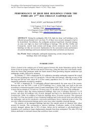
direct optimization method <strong>of</strong> structural parameters to minimize an error in a response time history(hereafter Direct method). The natural periods and damping factors <strong>of</strong> the system are identified and thestructural parameters, i.e. stiffness and damping coefficients, are updated from those assumed indesign. As the amplitude and the duration <strong>of</strong> this earthquake are abnormally important, the accuracy <strong>of</strong>the identification is improved by neglecting measure noises and using the large available quantity <strong>of</strong>data.Then, using the identified model, the performance <strong>of</strong> the semi-<strong>active</strong> base isolation system isanalyzed based on a response simulation with based on a record <strong>of</strong> an aftershock <strong>of</strong> April 7, 2011,during which the semi-<strong>active</strong> system is considered to be activated.BUILDING INFORMATIONFigure 1 shows the section views <strong>of</strong> Sousoukan. The locations <strong>of</strong> the isolation bearings are depicted inthe left diagram. The isolation layer is composed <strong>of</strong> 65 laminated rubber bearings, 24 passivehydraulic dampers and 8 semi-<strong>active</strong> dampers. The damping coefficient <strong>of</strong> the semi-<strong>active</strong> damperscan be switched between four stages. The right diagram shows the framing system <strong>of</strong> the building,which consists <strong>of</strong> steel, steel reinforced concrete and concrete filled steel tube. The building has ninelayers: seven floors above the ground and two basement floors. The short side direction <strong>of</strong> the buildingis shifted with 25 degrees from the north-south direction as shown in Fig. 1. In this paper, however, wecall the short side direction as the NS direction.There are two independent seismic observation systems in the building: one is for control <strong>of</strong> thesemi-<strong>active</strong> system and the other is for research. The accelerometers are placed at the foundation slab,the 2nd basement, the 1st and the 7th floors as well as the ground near the building. Design structuralparameters are presented in Table 7 <strong>of</strong> the appendix.NFig. 1 Section views <strong>of</strong> SousoukanESTIMATION OF DYNAMIC PROPERTIES WITH ARX MODEL AND N4SID METHODFirst, we estimated the 1st and 2nd natural periods, natural frequencies and damping factors <strong>of</strong> theentire building and the superstructure <strong>of</strong> the building from the accelerograms <strong>of</strong> the main shock (Fig.2) using an ARX model. The acceleration records at the foundation slab are used as input, and those atthe 7th floor as output. The acceleration records between 100 and 150 s, in which large amplitude <strong>of</strong>the principal shock is observed, are used for the estimation. The number <strong>of</strong> poles, the number <strong>of</strong> zeropoints, and dead time are set to 12, 4, and 1 respectively. In the analysis, all the accelerograms andother records are filtered by a third order Butterworth high pass filter with a cut-<strong>of</strong>f frequency <strong>of</strong> 0.125Hz considering causality. Tables 1 and 2 show the identified results for the entire building and the1026
superstructure, respectively.Then, the 1st and 2nd natural frequencies and damping factors <strong>of</strong> the entire building are alsoidentified using the N4SID method. The acceleration records at the foundation slab were employed forinput, and those <strong>of</strong> the 2nd basement, the 1st floor, and the 7th floors for output. The accelerationrecords <strong>of</strong> three time windows: between 20 and 60 s, between 100 and 150 s (the principal shock), andbetween 200 and 300 s, were used for estimations. The dimension <strong>of</strong> the state space model was 18 forthe EW direction and 17 for the NS direction. The identified results are shown in Table 3. Similarly,the 1st and 2nd natural frequencies and damping factors <strong>of</strong> the superstructure <strong>of</strong> the building wereestimated; the dimension <strong>of</strong> the state space model is 18 for the EW direction and 16 for the NSdirection. The identified results are shown in Table 4. The mode shapes are depicted in Fig. 3.1007th floor NS1007th floor EW[cm/s 2 ]00-1000 200 400 600 [s]1st floor NS100-1000 200 400 600 [s]1st floor EW100[cm/s 2 ]00-1000 200 400 600 [s]2nd basement NS100-1000 200 400 600 [s]2nd basement EW100[cm/s 2 ]00-1000 200 400 600 [s]Foundation slab NS100-1000 200 400 600 [s]Foundation slab EW100[cm/s 2 ]00-1000 200 400 600 [s]-1000 200 400 600 [s]Fig. 2 Observed records <strong>of</strong> the main shockTable 1 Estimated system parameters for the entire building based on an ARX modelDirection Mode Natural period [s] Natural frequency [Hz] Damping factorNS 1st 3.2 0.31 0.19direction 2nd 0.68 1.5 0.17EW 1st 3.1 0.32 0.24direction 2nd 0.71 1.4 0.16Table 2 Estimated system parameters for the superstructure <strong>of</strong> the building based on an ARX modelDirection Mode Natural period [s] Natural frequency [Hz] Damping factorNS 1st 1.1 0.91 0.05direction 2nd 0.36 2.8 0.08EW 1st 1.1 0.91 0.022direction 2nd 0.37 2.7 0.041027