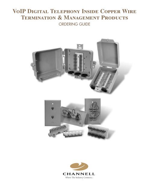
VoIP Digital Telephony Inside Copper Wire Termination ...
VoIP Digital Telephony Inside Copper Wire Termination ...
VoIP Digital Telephony Inside Copper Wire Termination ...
- No tags were found...

You also want an ePaper? Increase the reach of your titles
YUMPU automatically turns print PDFs into web optimized ePapers that Google loves.
<strong>VoIP</strong> <strong>Digital</strong> <strong>Telephony</strong> <strong>Inside</strong> <strong>Copper</strong> <strong>Wire</strong><strong>Termination</strong> & Management ProductsORDERING GUIDE®
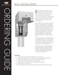
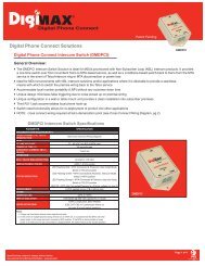
DESCRIPTION CHANNELL PART NO. UNITMIN.ORDERQTY.STANDARDPACKEnclosures and Terminal Blocks<strong>VoIP</strong> ProductsNOTE: Optional customer logoidentification available on covers.Consult Channell.4" x 5" Box with one10-Pair (1-in/9-out )bridging block installedVTB-45C1B10L3100 Carton 1 24/carton(36 cartonsper pallet)4" x 5" Box with one10-Pair bridging blockwith Security Systemconnectors (1-in/7-out +1-in/1-out) installedVSTB-45C1B10L3100 Carton 1 24/carton(36 cartonsper pallet)4" x 5" Box with dual5-Pair (2 x 1-in/4-out)bridging block installedVTB-45C1BD5L3100 Carton 1 24/carton(36 cartonsper pallet)4" x 5" Box with one6-Pair (1-in/5-out)bridging block installedVTB-45C1B06L3100 Carton 1 24/carton(36 cartonsper pallet)4" x 5" Box with one5-Pair (1-in/4-out)bridging block installedVTB-45C1B05L3100 Carton 1 24/carton(36 cartonsper pallet)2951/719-2600 • 800/423-1863 • FAX 951/296-2322 • www.channell.com
DESCRIPTION CHANNELL PART NO. UNITMIN.ORDERQTY.STANDARDPACKEnclosures and Terminal Blocks<strong>VoIP</strong> ProductsNOTE: Optional customer logoidentification available on covers.Consult Channell.5" x 5" Box with one10-Pair (1-in/9-out )bridging block installedVTB-55C1B10L3100 Carton 1 20/carton(36 cartonsper pallet)5" x 5" Box with one10-Pair bridging blockwith Security Systemconnectors (1-in/7-out +1-in/1-out) installedVSTB-55C1B10L3100 Carton 1 20/carton(36 cartonsper pallet)5" x 5" Box with dual5-Pair (2 x 1-in/4-out)bridging block installedVTB-55C1BD5L3100 Carton 1 20/carton(36 cartonsper pallet)5" x 5" Box with one6-Pair (1-in/5-out)bridging block installedVTB-55C1B06L3100 Carton 1 20/carton(36 cartonsper pallet)5" x 5" Box with one5-Pair (1-in/4-out)bridging block installedVTB-55C1B05L3100 Carton 1 20/carton(36 cartonsper pallet)951/719-2600 • 800/423-1863 • FAX 951/296-2322 • www.channell.com 3
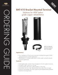
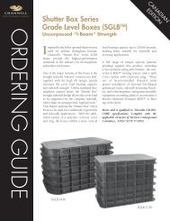
DESCRIPTION CHANNELL PART NO. UNITMIN.ORDERQTY.STANDARDPACKTerminal Blocks Only<strong>VoIP</strong> ProductsALL TERMINAL BLOCKS SOLD IN12" x 12" x 12" CARTONSMini-Rocker BridgingBlock, 10 Pair, 1-in/9-outMRB-10F0 Carton 1 100/ cartonMini-Rocker BridgingBlock, 10 Pair, withSecurity System connections,1-in/7-out≠+ 1-in/1-outMRSB-08F0 Carton 1 100/ cartonMini-Rocker BridgingBlock, Dual 5 Pair,Dual 1-in/5-outMRB-D5F0 Carton 1 100/ cartonMini-Rocker BridgingBlock, 6 Pair, 1-in/5-outMRB-06F0 Carton 1 200/ cartonMini-Rocker BridgingBlock, 5 Pair, 1-in/4-outMRB-05F0 Carton 1 200/ carton4951/719-2600 • 800/423-1863 • FAX 951/296-2322 • www.channell.com
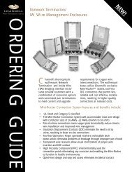
DESCRIPTION CHANNELL PART NO. UNITMIN.ORDERQTY.STANDARDPACKMini-Rocker Jacks<strong>VoIP</strong> ProductsFor Home Wiring Configured in a Star Pattern(Home Run Connectivity)1. Replace the existing RJ-11 jack nearest to the MTA withthe Mini-Rocker Duplex RJ-11 (MRJ11) product configuredfor straight splicing.2. Connect the voice port of the MTA to the RJ-11 port terminatedwith Yellow/Black wire as seen from the rear of theunit.3. Terminate a spare inside wire pair (Yellow/Black or Green/White for example) to the Mini-Rocker connector connectedto the Yellow/Black RJ-11 jack.4. Terminate the working pair (Red/Green or Blue/White forexample) to the Mini-Rocker connector from the RJ-11 portterminated with Red/Green wire as seen from the rear ofthe unit.5. For other phone extensions that require replacement RJ-11jacks, use the single MRJ11 jack configured for straightsplicing and terminate the working pair to the Mini-Rockerconnector.For Home Wiring Configured in a Bus Pattern(Looped-through Connectivity)1. Replace the existing RJ-11 jack nearest the MTA with theMini-Rocker Duplex RJ-11 (MRJ11) product configured forbridged splicing.2. Connect the voice port of the MTA to the first RJ-11 port.3. Cut the working pair and terminate one end to one of theMini-Rocker connectors on the first RJ-11 port.4. Connect the remaining Mini-Rocker connector to the secondRJ-11 port using one of the Mini-Rocker connectors ofthe second RJ-11 jack.5. Terminate the other end of the working inside wire pair tothe remaining Mini-Rocker connector on the second RJ-11jack.6. For other telephone extensions that require replacementRJ-11 jacks, use the single MRJ11 configured for bridgedsplicing. Cut the working inside wire pair and terminateeach end to one of the Mini-Rocker connectors on the rearof the unit.Mini-Rocker Jack singleconnector flush-mountconfiguration, straightsplicingMRJ11CXF1SS Carton 1 50/carton(Duplex flush-mount straight splice)Mini-Rocker Jack singleconnector flush-mountconfiguration, bridgedsplicingMini-Rocker Jack duplexconnector flush-mountconfiguration, straightsplicingMRJ11CXF1SB Carton 1 50/cartonMRJ11CXF2SS Carton 1 50/carton(Duplex flush-mount bridged splice)Mini-Rocker Jack duplexconnector flush-mountconfiguration, bridgedsplicingMRJ11CXF2SB Carton 1 50/carton6951/719-2600 • 800/423-1863 • FAX 951/296-2322 • www.channell.com
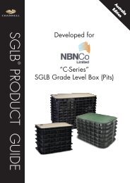
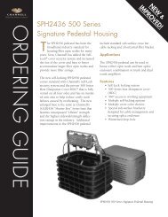
Applications<strong>VoIP</strong> ProductsVoice Connection from Existing Modem LocationStep 1Line 2Line 1Step 2ExistingTelcoNIDVoice Connection fromExisting Modem Instructions:Step 3Voice Line 1Voice Line 2HousePhoneExtensions1. Remove existing customer insidewiring from Telco NID.2. Relocate each wire pair to newbridging module output connectors.3. Connect voice service connectionfrom cable modem/MTA to inputconnection on the bridging module.BroadbandConnectionCableModem/MTAVoice Connection from Modem LocationWith Security System Step 2Step 1HousePhoneExtensionsExistingTelcoNIDStep 4BroadbandConnectionCableModem/MTAStep 5Step 3SecuritySystemSecurity Connection Instructions:1. Remove existing customer inside wiring from Telco NID.2. Relocate and terminate each wire pair of the bridging section ofthe MRSB block. The bridging section is identified by theconnectors facing outward from the block.3. Terminate the feed pair to the security system using one of thesecurity connectors of the MRSB block. The security connectorsface inward on the block.4. Terminate the return pair from the security system to the bridgingsection of the MRSB block.5. Connect the voice service connection from the cablemodem/MTA to the remaining security connection on the MRSBblock.951/719-2600 • 800/423-1863 • FAX 951/296-2322 • www.channell.com7
®AMERICAS: Channell Commercial Corporation, Temecula, CA • Tel. 800.423.1863 • Fax. 951.296.2322CANADA: Channell Canada, Inc. • Tel. 905.565.1700 • Fax. 905.565.8080WORLDWIDE HEADQUARTERS: Channell Commercial Corporation • Tel. 951.719.2600 • 26040 Ynez Road • P.O. Box 9022 • Temecula, CA 92589-9022 USAAll specifications subject to change without notice. www.channell.com Printed in U.S.A. CH06-100 06065MTAMini-Rocker is a registered trademark of Channell Commercial Corporation.