Bachelor Thesis A Qualitative Analysis of Two Automated ...
Bachelor Thesis A Qualitative Analysis of Two Automated ...
Bachelor Thesis A Qualitative Analysis of Two Automated ...

Create successful ePaper yourself
Turn your PDF publications into a flip-book with our unique Google optimized e-Paper software.
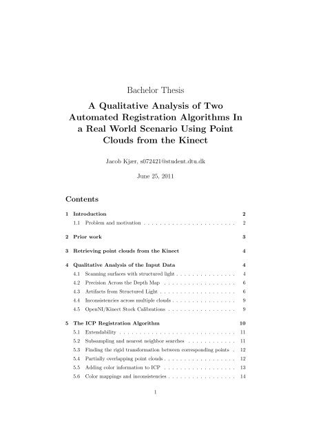
<strong>Bachelor</strong> <strong>Thesis</strong>A <strong>Qualitative</strong> <strong>Analysis</strong> <strong>of</strong> <strong>Two</strong><strong>Automated</strong> Registration Algorithms Ina Real World Scenario Using PointClouds from the KinectJacob Kjær, s072421@student.dtu.dkJune 25, 2011Contents1 Introduction 21.1 Problem and motivation . . . . . . . . . . . . . . . . . . . . . . . 22 Prior work 33 Retrieving point clouds from the Kinect 44 <strong>Qualitative</strong> <strong>Analysis</strong> <strong>of</strong> the Input Data 44.1 Scanning surfaces with structured light . . . . . . . . . . . . . . . 44.2 Precision Across the Depth Map . . . . . . . . . . . . . . . . . . 64.3 Artifacts from Structured Light . . . . . . . . . . . . . . . . . . . 64.4 Inconsistencies across multiple clouds . . . . . . . . . . . . . . . . 94.5 OpenNI/Kinect Stock Calibrations . . . . . . . . . . . . . . . . . 95 The ICP Registration Algorithm 105.1 Extendability . . . . . . . . . . . . . . . . . . . . . . . . . . . . . 115.2 Subsampling and nearest neighbor searches . . . . . . . . . . . . 115.3 Finding the rigid transformation between corresponding points . 125.4 Partially overlapping point clouds . . . . . . . . . . . . . . . . . . 125.5 Adding color information to ICP . . . . . . . . . . . . . . . . . . 135.6 Color mappings and inconsistencies . . . . . . . . . . . . . . . . . 141
6 The Feature-based Registration Algorithm 156.1 Implementation considerations . . . . . . . . . . . . . . . . . . . 166.2 Registering to multiple clouds at the same time . . . . . . . . . . 177 The s<strong>of</strong>tware 188 Implementation 199 Performance 2110 Conclusion 211 IntroductionIn fall 2010 Micros<strong>of</strong>t released the Kinect. It is a piece <strong>of</strong> hardware whichincorporates a structured light projector, an infrared camera, a color camera,and various other peripheals like an array <strong>of</strong> microphones and an accelerometermeant for adjustment <strong>of</strong> a built in pivot motor. In this report, the two camerasare put to use.A structured light camera is able to measure the depth <strong>of</strong> a given point inan image relative to its viewpoint. Given that the x and y position <strong>of</strong> anypoint in the image plane is implicitly given, having its depth gives us its threedimensional projective coordinates. On such coordinates one can perform areverse perspective projection in order to extract the 3-dimensional cartesiancoordinate <strong>of</strong> the point relative to the viewpoint <strong>of</strong> the camera. Performingsuch a transformation on all points in the image plane results in a set <strong>of</strong> pointswhich we call a point cloud. A point cloud can be reprojected and exploredfrom all viewpoints independently <strong>of</strong> how it was generated.Given that the Kinect also has a normal color camera, this can be used inconjunction with the structured light camera to extract a colored point cloud<strong>of</strong> a given scene.1.1 Problem and motivationNow, having a point cloud <strong>of</strong> a scene is nice. But exploring it from differentviewpoints, one will discover large holes in the objects in the scene caused byocclusion. And even more, what about that which lies behind the camera? Asingle point cloud captured by the Kinect can tell us nothing more about thescene than the surface which is visible from the viewpoint from which it wascaptured.Point cloud registration is the act <strong>of</strong> matching such point-clouds captured fromdifferent viewpoints with each other so that they form a more complete representation<strong>of</strong> a given scene. The result <strong>of</strong> a registration <strong>of</strong> two point clouds issome information which can be used to align the clouds.2
With good registration, surface scanners like the Kinect can be a very usefulaid in re-construction <strong>of</strong> the real world on a computer, which has many uses.Computer game developers can easily make levels based on real life, and alsovery quickly generate in-game assets from real-world objects which they wouldotherwise have to sculpt from scratch. Educational institutions <strong>of</strong> all kinds canleverage the benefits <strong>of</strong> real world reconstruction in some <strong>of</strong> their teaching. Realestate brokers can use 3D reconstructions <strong>of</strong> homes to sell better. Geologists andarchaeologists can use it as a part <strong>of</strong> their mapping processes <strong>of</strong> undergroundcaves and ancient sites to capture details which would otherwise be very costlyto describe. This list <strong>of</strong> scenarios in which this technology can be used is farfrom exhaustive, but the wide variety <strong>of</strong> seemingly unrelated field in the listshould give an idea that it is quite interesting to look further into.Registration can be done by hand, but it is time-consuming, tedious, and possiblyimprecise. However, automatic registration algorithms already exist. <strong>Two</strong><strong>of</strong> these are Iterative Closest Point (ICP) (plus some extensions there<strong>of</strong>) andone based on Optical Flow in the Kinect color image. The goal if this project isto implement these two algorithms (plus variants) and then analyze them in aset <strong>of</strong> real world scenarios in which they are used to align point clouds capturedby the Kinect. In what situations can the Kinect be used, and how well do thealgorithms perform with regards to speed and precision?Another goal, and a major motivation for this project, is to create a tool whichinterfaces with the Kinect for point cloud capturing and exposes these automaticregistration algorithms for usage on them. It will be built with the intention<strong>of</strong> testing the algorithms, but will also make it possible for end users to createand export their own aligned scans <strong>of</strong> real world objects and scenes. In thepast when investigating registration algorithms, range scanners were not easilyavailable, and therefore there has been little incentive to focus on creating acomplete workbench. With the release <strong>of</strong> the Kinect, there definitely is, andthe s<strong>of</strong>tware should be a milestone or prototype from which experiences can bedrawn.Registration, on a higher level, recognizes (registers) parts <strong>of</strong> one dataset inanother. Therefore registration algorithms will not work on two datasets fromcompletely unrelated viewpoints in a scene. The must have something in common,and the more the better. Therefore is no focus on aligning clouds takenfrom arbitrary positions to each other, nor is there any focus on scenes in whichany kind <strong>of</strong> movement occur. Only clouds taken from similar viewpoints are infocus.2 Prior workslam6d, stuff on youtubethen burrus (march), pointcloud library (may), willow garrage3
3 Retrieving point clouds from the KinectWhile the Kinect was initially released as a gaming peripheral for the Xbox360 console, a set <strong>of</strong> <strong>of</strong>ficial drivers were released around new year 2011 as part<strong>of</strong> the OpenNI project along with a very useful library for interfacing with thedevice and a collection <strong>of</strong> high-level computer vision functions. The OpenNIdrivers are <strong>of</strong>ficial in the sense that they are backed by the developer <strong>of</strong> theKinect hardware, Primesense. In the end <strong>of</strong> June 2011, Micros<strong>of</strong>t also releasedtheir take on an <strong>of</strong>ficial SDK.OpenNI provides everything needed for extracting a colored pointcloud fromthe Kinect. It can extract corresponding depth and color maps, calibrate themagainst each other, and perform the reverse perspective projection to cartesiancoordinates as described in the introduction. Calibration <strong>of</strong> the color and depthmap against each other is necessary because the source cameras for these mapsare physically <strong>of</strong>fset from each other on a horizontal axis. Also, the camerashave difference fields <strong>of</strong> view, and therefore different view frusta. The points onthe depth map must be re-projected to the viewpoint <strong>of</strong> the color map for goodcorrespondence. As written earlier, OpenNI can do that.OpenNI also abstracts all internal scales for depth and position to metric values,where 1 meter = 1000 units. This is useful as it means that the device canexploited for measuring object sizes and lengths in a scene. It also makes iteasy to measure the precision <strong>of</strong> two alignments by comparing the translationvectorto known camera movements.4 <strong>Qualitative</strong> <strong>Analysis</strong> <strong>of</strong> the Input DataThe following subsections are dedicated to analyzing the quality <strong>of</strong> the inputdata and aspects which can be related to this. When does the Kinect work well,and when does it not? It is important when planning a reconstruction to knowwhat one can expect from the camera.Through OpenNI the Kinect provides both color (24-bit RGB) and depth (formattingdescription follows) images in 640x480 resolution at a speed <strong>of</strong> 30Hz.This gives a theoretical upper limit <strong>of</strong> 640 × 480 = 307200 points in a pointcloud. In practice, a scene with good capturing conditions will result in a cloud<strong>of</strong> at most ca. 265000 points, due to how the depth map will map onto the colorimage, which is captured with a wider field <strong>of</strong> view. The quality <strong>of</strong> the colorimages is about as good as a decent webcam, and bayer noise is noticeable.4.1 Scanning surfaces with structured lightThe following is based on info from the ROS Team’s technical analysis <strong>of</strong> theKinect[1].The Kinect uses its infrared camera along with its structured light projector toestimate the surface <strong>of</strong> a scene as seen from the camera viewpoint. The projectorprojects an infrared pattern onto the scene and the IR camera captures it.4
Figure 1: A Kinect-like setup with a single point-projectorTo illustrate how surface measurement using structured light works, see figure 1.It is a Kinect-like setup in which a projector is projecting just a single point (avery simple pattern) into space along the red line. It is captured by the cameraonce it hits a surface. There are three planes in the illustration; a referenceplane, a plane closer to the camera than the reference plane, and a more distantplane. When the point hits a surface in the close plane it will appear furtherright in the image than if it was hitting a surface in the reference plane. Likewise,when the point is projected onto an object on a plane which is more distant thanthe reference plane, the point will appear more to the left. When the origin anddirection <strong>of</strong> the light is known beforehand, and the horizontal position <strong>of</strong> thedot is known for a reference depth, then it is possible to find out the depth <strong>of</strong>the surface which the point hits.Now, the Kinect does not project a single point, but a large amount <strong>of</strong> pointsin an intricate pattern. The Kinect has an image reference <strong>of</strong> what the patternlooks like from the cameras viewpoint when all point in the surface are at acertain, known distance. It finds correspondences between the points IR patternwhich it captures, and this reference pattern. By comparing the horizontalposition <strong>of</strong> a point in the captured image to its corresponding horizontal positionin the reference image, a horizontal delta value can be extracted, which inturn can be used to calculate the depth <strong>of</strong> the pixel just like described in theabove paragraph with the single-point projector. The Kinect itself actuallydoes not calculate the depth, but returns a more abstract value for the hostsystem to handle (see next section). While OpenNI abstracts this away for thedeveloper, libfreenect, another driver and library platform, makes these 11-bitvalues available[REFER:Burrus].5
4.2 Precision Across the Depth MapAccording to Nicolas Burrus, who pioneered with information about the Kinectfrom his own experiments, the depth <strong>of</strong> a point z can be calculated in metersfrom the raw disparity <strong>of</strong> the point d (as provided by the Kinect hardware)using the following equation:z = 1.0/(d · −0.0030711016 + 3.3309495161)I did some analysis <strong>of</strong> the equation and found it peculiar; d is an 11-bit integerwhich ranges from 0 to 2047. z will change sign from positive to negative whend is around 1084, so any practical use <strong>of</strong> values beyond that are useless for depthmeasurement. I carried out tests with the Kinect pointing straight at a wall andfound that it is was to unable to reliably measure depth values below 50 cm (seefigure 2). These facts mean that only d values <strong>of</strong> about 434 to 1084 representsactually measurable depth values. This is 650 unique disparity values, whichis not a lot. Of these, all values up to 759 represent a depth <strong>of</strong> less than 1.0m, meaning that half <strong>of</strong> all useful disparities output by the Kinect are in therange 50 cm to 1 m. And it falls exponentially; only 16 values in the range <strong>of</strong>disparities correspond to depths between 4 and 5 meters.This dramatic decrease <strong>of</strong> fidelity was found to be correlating with my findingsin figure 3 where a large gym ball was shot at two distances, approximately 2.5mand 80 cm. The difference in precision is very noticeable - at a distance ballis hardly discernible when viewed from the side, while at close point it appearsround and smooth.So not only will objects which are far away from the viewer consist <strong>of</strong> less pointsbecause they take up a smaller area <strong>of</strong> the picture, but they will also be morecoarse. The lesson here is that for any object more distant than 2.5-3.0 m,one cannot expect a faithful representation <strong>of</strong> its surface, and that any delicatedetails must be captured in a range <strong>of</strong> 60 cm to 1.5 m. Whether the hardwareactually is precise at higher ranges is irrelevant because <strong>of</strong> the format in whichit returns its measurements is <strong>of</strong> too low fidelity.My unknowing guess is that the reason for this depth format is that as objectscome further away from the viewer, the effect <strong>of</strong> binocular disparity lessens, andthereby also the precision <strong>of</strong> the depth measurement, so the engineers behindthe hardware probably did not see much benefit in leaving any useful depthinformation in these ranges.4.3 Artifacts from Structured LightBecause the camera and projector are <strong>of</strong>fset by design, this means that notall points which are visible from the camera can always be illuminated by theprojector. As a result holes may appear in the depth map where the projectedpattern has been occluded (see figure 4)In general, infrared structured light will have many errors in environments consists<strong>of</strong> anything but diffuse surfaces, or environments with other sources <strong>of</strong>infrared light. For example the light <strong>of</strong> the sun, which created a hole in the testobject (a gym ball) in figure 4 due to too much light being reflected back.6
Figure 2: Emperical test <strong>of</strong> minimum supported depth <strong>of</strong> the hardware. Left: Atover 50 cm, the wall is captured by the Kinect (as shown on the screen). Right: Atless than 50 cm, it is not. While these distances are approximate, one should operatewith the Kinect well beyond them for the best results.Figure 3: Example <strong>of</strong> how depth-map fidelity falls drastically as distances increase.A large gym ball was shot at two different distances to illustrate this. Left: the ballis over 2 m away from the camera. Right: less than 1 m away. Both clouds are shownfrom the side.7
Figure 4: Example <strong>of</strong> projector-shadowing and IR interference caused by sunlight.Figure 5: Edge <strong>of</strong> a point cloud warping towards the viewer. This is supposed to bea straight wall. The green line was added post-capture to give an indication <strong>of</strong> wherethe edges <strong>of</strong> the wall should be.8
Figure 6: Inconsistencies across multiple pointclouds which together make up part<strong>of</strong> a room. The back wall shows signs <strong>of</strong> being constructed from several clouds withchanges in apperance from cloud to cloud. The chances in shade are so large that itis hard for the eye to discern it as a single continuous wall.4.4 Inconsistencies across multiple cloudsMost materials do not spread incoming light evenly in all directions. Solidmaterials more <strong>of</strong>ten than not have some amount <strong>of</strong> specular reflection. Thismeans that one point on a surface will most likely change appearance whencaptured from different viewpoints. In the process <strong>of</strong> capturing a scene whichis illuminated by sunlight the weather may change slightly, and if it does thenso will the appearance <strong>of</strong> the shades, shadows and colors. Another source <strong>of</strong>change in lighting conditions may even be the user <strong>of</strong> the Kinect moving aroundthe scene.So some times the precise shade <strong>of</strong> an object will be inconsistent across multiplepoint clouds, as it is shown in figure 6.An analysis <strong>of</strong> what this means to the registration algorithms is described inthe sections for the algorithms themselves as the impact is different for each <strong>of</strong>them.4.5 OpenNI/Kinect Stock CalibrationsFor the purpose <strong>of</strong> capturing point clouds, and computer vision in general,cameras provide the nicest data when they capture pictures in the way that anidealized pinhole camera would. Without going into too many formal details,it means that the center <strong>of</strong> the picture corresponds to what is directly straightin front <strong>of</strong> the camera, that all straight lines are perfectly straight, and thatthere are no other lens-caused distortions (such as fish eye effects). Most 3Dcomputer games use this ”perfect” camera model.The ROS team empirically measured how much their Kinect cameras divertedfrom the pinhole camera model and found the difference to be very small[1].This is good.9
Inspecting the point clouds provided by the Kinect through Kinect at OpenNIat close point, OpenNI’s calibration <strong>of</strong> the depth and color map is very decentout <strong>of</strong> the box. For distant objects, a near-perfect calibration is hard to acquire.Part <strong>of</strong> this can be attributed to the lowered precision <strong>of</strong> the depth measurementat longer distances, and is therefore hard to do anything about client side.At last, the corners <strong>of</strong> any point cloud will may slight warping (see figure 5).This cannot be solved with calibration, as even hand-calibrated clouds have thisissue, so it is more likely due to a flaw in the lenses <strong>of</strong> the IR projector or IRcamera causing the edges to be distorted. As the IR data is used in the Kinecthardware, correcting these distortions properly would require a large effort.For purpose <strong>of</strong> this project, it was decided that the quality <strong>of</strong> the stock OpenNIcalibration is not likely to be a major source <strong>of</strong> error, and that it thereforeis considered good enough, especially when taking into account that it wouldadd extra layers <strong>of</strong> complexity to both development and usage <strong>of</strong> the s<strong>of</strong>twareworkbench.5 The ICP Registration AlgorithmThe Iterative Closest Point (ICP) algorithm is a very common registration algorithmdescribed in 92 in a paper by Zhengyou Zhang[5]. It goes as following,where C m denotes a point cloud which is to be registered and moved to anotherpoint cloud with a static position, C s :1. For all points p m in C m , find the nearest neighbor p s in C S .2. Find the rigid transformation, an orthogonal rotation R and a translationt, which minimizes the squared distances between the neighboring pairs(enumerated with i):minR,t3. Apply the transformation to C m .∑||(Rp mi + t) − p si || 2i4. Repeat until the algorithm has converged or till a desired result has beenobtained.Worded differently, the algorithm simply picks a set <strong>of</strong> temporary correspondentsnaively across the two input clouds based on their distance, move themcloser to each other to make the best fit, and then picks a new set <strong>of</strong> temporarycorrespondents based on the new positions <strong>of</strong> the point clouds and repeatsthe procedure until they are not really temporary any more (the algorithmhas converged). It is somewhat naive compared to the feature-based algorithmwhich will be described in the next section, but it apparently works well sometimes[REFER:ALTING!][5][10].A prerequisite for a good registration is that the approximate motion betweenthe viewpoints from which the two input clouds for the algorithm is known.Zhang describes this in the introduction <strong>of</strong> his paper[5]. Arbitrarily positionedclouds are unlikely to work well.10
5.1 ExtendabilityThe algorithm here is the most basic version given by Zhang, and it is also inthis form which it has been described in Computational Geometry Processing[6].The algorithm is however quite extensible. In Efficient Variants <strong>of</strong> the ICPAlgorithm, they categorized areas in which extensions can be to[7]:• How points are selected for sampling across the two input clouds.• How points are matched against each other. Alternatives to nearest neighborsearches exist.• How matches are weighted against each other.• And, related: whether some matches should be rejected or not.• How the sum <strong>of</strong> squared distances (error) is minimized in step 2 <strong>of</strong> theprocedure.Zhang himself proposed some additional heuristic for limiting the maximal rangewhen searching for nearest neighbors in his paper[5].TODO: Skriv om hvilke extensions der er lavet i det her projekt og hvordan devinkler p ovenstende extension model.5.2 Subsampling and nearest neighbor searchesBecause each point cloud <strong>of</strong>ten consists <strong>of</strong> more than 200000 points, searchingfor nearest neighbors for every point is infeasable. [7] shows that it is is not necessaryto sample all points, because a smaller subset <strong>of</strong> randomly chosen pointsworks equally well in many cases with similar convergence rate and error. Soit has been decided to use random sub-sampling in the final implementation,picking points for nearest neighbor searches by traversing randomly through theinput cloud with random sized steps between 1 and 150 (uniformly sampled).This averages to every 75th point, and translates to ca. 2700 searches per. iteration,varying from dataset to dataset. It increases execution time accordingly.Nearest neighbor searching is also expensive for such large datasets. Naivesearches can be done in linear runtime by computing the distance to all pointsin the target cloud and taking the smallest. But it is too expensive for this application.Fortunately, there exists numerous <strong>of</strong> algorithms and data structuresto speed up such a search. The most efficient is likely to move it to the GPU[11],but such a demanding optimization is beyond the scope <strong>of</strong> this project. Instead,in order to obtain acceptable run times, an <strong>of</strong>f-the-shelf kD-tree implementationfrom the GEL library has been used in the implementation. Zhang also used akD tree to speed up his ICP implementation[5].11
5.3 Finding the rigid transformation between correspondingpointsThe following instructions are a paraphrase <strong>of</strong> the instructions given in ComputationalGeometry Processing[6] for finding the rigid transformation between aset <strong>of</strong> corresponding points.The translation part t <strong>of</strong> the rigid transformation is defined as the vector whichwill translate the center <strong>of</strong> mass <strong>of</strong> the pair-matched points in C m to the center<strong>of</strong> mass <strong>of</strong> the corresponding points in C s :t = 1 nn∑(p mi − p si )i=1Where n denotes the amount <strong>of</strong> matched pairs found in step 1 <strong>of</strong> the algorithm,and i is used to enumerate these point pair entries so that (p mi , p si ) denotes thei’th pair. Notice that some points <strong>of</strong> C s may be the closest neighbor for severalpoints in C m , meaning that they will be weighted more in the center <strong>of</strong> masscalculations. This is intentional.Now onto R. If we have a matrix H, defined as:H =n∑p mi p T si − 1 n n ( ∑ n∑p mj )( p sk ) Ti=1Then from the singular value decomposition <strong>of</strong> H = UΣV T , it can be shownthat R = UV T . If there are some errors or some noise in the dataset, it willstill work.After I tried this procedure out in practice, I found that it did not work asintended. But after a little trial and error, it turned out that finding R and tonce, applying the transformation, and then doing it again seems to give thedesired result. This does, however, mean that the neighbor pairs must be storedexplicitly in between those two iterations, as they are needed for calculating tand H twice. Alternatively they must be calculated again, which can be veryexpensive.It was decided not to dwelve further into the problem as it two iterations justseem to work. The s<strong>of</strong>tware needs a rigid transformation, this solution providesit.j=1It seems that I was not the only person who hadk=15.4 Partially overlapping point cloudsICP needs to be extended to support partially overlapping point clouds. Figure7 illustrates why. It shows two partially overlapping point sets, a blue and ared one. Attempting to register the blue onto the red with ICP will create aset <strong>of</strong> neighbors in the first step <strong>of</strong> the algorithm. These neighbor-relations areimplied by the black lines connecting the points <strong>of</strong> the sets, and they illustrate12
Figure 7: <strong>Two</strong> partially overlapping sets <strong>of</strong> points. It has been attempted to finda nearest neighbor (and proposed correspondent) from the red set for all points inthe blue set. However, for all those blue points but one in the green-tinted area, theproposed correspondent is bad because the red set is discontinued. This shows whymatched pairs containing edges must be discarded.a problem: All blue points in the green-tinted area have the same neighbor:the left-most point <strong>of</strong> the red point set. All but one <strong>of</strong> these neighbors arebad correspondents, and taking them into account when calculating the rigidtransformation will likely result in a bad result.The solution is to discard all correspondents which contain such ”edges” likethe one which the points in the green tinted area are linked to. ”Edges” is aloosely defined term, and for point clouds from arbitrary sources it might bea hard problem to define them. But with data from the Kinect, it is moregracious. I define these edges as discontinuities in the depth map from which acloud has been generated, as it represent discontinuities in the surface which itis capturing.5.5 Adding color information to ICPICP finds correspondents based solely on their locations. But not only is onepoint being close to another an indicator <strong>of</strong> correspondence, so is a similar color.So by extending ICP to take similarity <strong>of</strong> color into account, better correspondencesmight be obtained. This requires changes to the nearest neighbor search.Instead <strong>of</strong> measuring distances between two points based solely on their positionin an (x, y, z) coordinate system, distances between more abstract vectors in a(x, y, z, [color]) space can be used to determine correspondence. [color] is oneor more elements containing values related to color information. For examplehue or RGB, i.e a 4-dimensional (x, y, z, H) or a 6-dimensional (x, y, z, R, G, B)search space. In this way, both color and spatial spaces are searched at the sametime for correspondents.One thing to take into account is the relative size <strong>of</strong> (x, y, z) and ([color]) spaces,because they run in different intervals. For a point cloud from the Kinect in amedium-size living room, the intervals <strong>of</strong> the spatial coordinates run somewherebetween 1.5 and 4 meters. Scaling the color space so that it runs over larger orsmaller intervals will decide how the two spaces are weighted against each otherwhen finding correspondents.13
Figure 8: <strong>Two</strong> partially overlapping sets <strong>of</strong> colored points in which the nearest neighborsearch for the points in the green-tinted area has given a set <strong>of</strong> bad correspondents.These points should be discarded, but as their common proposed correspondent is notan edge, this cannot be used to rule them out. Therefore a separate nearest neighborsearch which does not take colors into account must be performed to rule them out.There however is a pitfall when adding color information to the nearest neighborsearch in partially overlapping clouds. Points whose closest spatial neighbor intheir target cloud is an edge must be discarded when calculating the rigid transformation.But when searching the combined (x, y, z) and ([color]) space, theclosest point might not be an edge when it should be. This is the case in figure8 where the left-most blue points, those in the green-tinted area, are matchedto a non-edge even they should be discarded for not have a correspondent inthe other point set. Therefore, when searching combined spaces for partiallyoverlapped point clouds, a separate search must be made in (x, y, z) space onlyin order to determine whether a point-pair should be discarded or not.5.6 Color mappings and inconsistenciesDifferent color mappings will have different strengths and weaknesses whenadding color information to the nearest neighbor search space. When decidingwhich one to use, the fact that color information is likely to be somewhatinconsistent (section 4.4) has to be taken carefully in account in the decisionmaking process.RGB is a straightforward color mapping. In clouds with no inconsistencies, it isvery precise because it provides 3 channels <strong>of</strong> independent color information foreach point. But it is not invariant to changing light conditions, as figure 9 seeksto illustrate. It shows two captures a scene, in between which the direction <strong>of</strong>incoming light has changed. In image A, the spheres are lit from above. In imageB, the spheres are lit from the side in a fashion so that the large green sphereis shadowing the the little red sphere, resulting in a much darker shade. As aresult, attempting to find correspondents between the two images by measuringthe distance between two (r, g, b) vectors will result in a bad match: the lightpart <strong>of</strong> the red sphere in image A and the light part <strong>of</strong> the green sphere inimage B. The reason for this is that the RGB values for these bright areas areare closer to each other in (r, g, b) space (R: 254, G: 224, B: 244 vs. R. 208, G:248, B: 196) than they are to the RGB values for the ball in the shade (R: 99,G: 35, B: 35).14
Figure 9: An illustration <strong>of</strong> how comparing colors based on RGB values in sceneswith changing light conditions may not work well. Here, the distance from the lightestcolor-value <strong>of</strong> the red ball in image A isFigure 10: Hue values mapped to a non-cyclic interval. Even though the cyan colorsat the extremes <strong>of</strong> the interval are visually close to each other, measuring the distancebetween them with this mapping with not reflect that.However, in figure 9, the hue <strong>of</strong> the red ball does not change in between thetwo images. Therefore searching a (x, y, z, H) space may be a more robustway to improve searches for correspondents, even across somewhat inconsistentdatasets.The hue <strong>of</strong> a color is represented by an angular value in a cyclic interval ratherthan a scalar in a linear interval like that <strong>of</strong> the elements <strong>of</strong> RGB. This meansthat a hue <strong>of</strong> 1 ◦ is closer to a hue <strong>of</strong> 359 ◦ than to a hue <strong>of</strong> 5 ◦ . So distanceevaluations in (x, y, z, H) space should be changed to reflect this. But is itnecessary? What if this cyclic property is ignored? All hue values can be fittedto a −180 ◦ ..180 ◦ interval, and then used them as if they are just normal scalarvalues. Cyan shades will end up in arbitrary ends <strong>of</strong> the interval because <strong>of</strong>they lie on the discontinuity <strong>of</strong> the interval with a hue <strong>of</strong> ca. 180 ◦ = −180 ◦ .But all other hues are going to be unaffected. Since hues are not expected tochange much from image to image, unless there are a lot <strong>of</strong> cyan objects in thescene, only a minor part <strong>of</strong> the interval is going to be rendered unusable. S<strong>of</strong>or the sake <strong>of</strong> simplicity, it can be chosen to ignore the cyclic property in animplementation <strong>of</strong> this mapping.The weakness <strong>of</strong> hue is that it may not perform well in scenes with large areaswith low color saturation, such as which walls, grey stones or black tiles, becausethe hue <strong>of</strong> non-saturated shades is undefined.6 The Feature-based Registration AlgorithmThe feature-based registration algorithm is similar to ICP in that it searchesfor a set <strong>of</strong> matched pairs across the two input clouds, and then finds the rigid15
transformation which minimizes the sum <strong>of</strong> squared distance between them.However, instead <strong>of</strong> finding a temporary set <strong>of</strong> correspondents based on someheuristics, it aims to find a set <strong>of</strong> actually correct correspondents across the twoinput clouds without multiple iterations.It goes as following:1. Detect invariant features[8] in the color-images from which C m and C sobtain their color information.2. Extract two sets <strong>of</strong> feature-descriptors from the input images and matchthem against each other.3. Extract a set <strong>of</strong> matched pairs in 3D-space by corresponding the location<strong>of</strong> each feature to the point in the point cloud which it maps to.4. Find the rigid transformation which minimizes the squared distance betweenthe matched pairs in 3D space. One can use the same procedurefor this as described for ICP in section 5.3.This algorithm has a good synergy with ICP, but different prerequisites. Whileit does not require points to be somewhat aligned initially, but it is dependenton the data coming from the kind <strong>of</strong> data source which the Kinect provides.The synergy is, that if it does not result in a perfect registration but just anapproximation, such an approximation will be a good starting point for ICP.6.1 Implementation considerationsDetection and matching <strong>of</strong> features are complex problems in themselves, butthe freely available library OpenCV <strong>of</strong>fers multiple ready-made solutions whichcan be used for that.The algorithm is adaptable to several <strong>of</strong> these solutions to finding correspondencesin the two source images. In the product, SURF was chosen because:• It is available in OpenCV and easy to use.• It is more than an order <strong>of</strong> magnitude faster than SIFT and performscomparably well[9].• It performs well in images with changing light conditions[9], and such isthe nature <strong>of</strong> the data on which it will be working (see 4.4).• I performed practical comparisons with some <strong>of</strong> the other solutions availablein OpenCV (SIFT, FAST) and found that SURF was by far the bestfor the job in terms <strong>of</strong> precision and speed.The descriptor matching in OpenCV is not designed specifically for rigid poseestimation in images from static scenes, or to take into account that a thirddimension can be added to the location <strong>of</strong> the descriptors (if it evens takeslocation in an image into account when matching).16
When detecting features with SURF, there are multiple input parameters willchange the outcome <strong>of</strong> the process. OpenCV has made some wrappers calledadjusters, which abstracts these parameters away in favor <strong>of</strong> an interval in whichthe user may signify the desired amount <strong>of</strong> features to be detected. This wrappermay use several iterations <strong>of</strong> detection to adjust the underlying parameters togive a result which fits this interval, but in return it means that it is hopefullymore robust and adaptable to different scenes.SURF does not support color images, so all images were converted to gray scalefirst.6.2 Registering to multiple clouds at the same timeWhen matching clouds, then the more they overlap, the more correspondentsthey will have. This is a trivial observation. Therefore it makes sense to captureclouds from only slightly different viewpoints when reconstructing a scene.Also, when reconstructing a room, the camera is going to be at similar viewpointsmany times. This means that a newly captured cloud is likely to havecorrespondents in multiple clouds rather than just one.I came up with a procedure for matching one cloud against several clouds atthe same time. Something like it is also described in (REFERENCE: WILLOWGARAGE):• Register the newly acquired cloud onto the previous one. Keep track <strong>of</strong>the amount <strong>of</strong> matches found, N prev .• Register the cloud against all clouds in the scene, optionally ignoring thosewhich are unlikely to contain matches (based on viewpoints) for speedups.Keep track <strong>of</strong> all sets <strong>of</strong> correspondents.• For each new set <strong>of</strong> correspondents, discard it if it has a size N < 1 2 N prevor if N < 10 in order to increase the robustness <strong>of</strong> the registration. Sets<strong>of</strong> only a few correspondents may contain many outliers.• Construct a rigid transformation from the remaining sets <strong>of</strong> correspondent.The immediate benefit from registering against multiple clouds at the time isthat it evens out errors across multiple point clouds, rather than accumulatingthem in the fashion that always matching against single clouds will. Due tothe nature <strong>of</strong> these errors, it was hard to illustrate in a figure, but two files,erroraccumsingle and erroraccummulti has been included with this reportas examples for to explore on a capable computer. These are the results <strong>of</strong> areconstruction in which the viewpoint has swept from the left side <strong>of</strong> a room tothe right, and then back to its initial position. Both clouds have been registeredwith feature-based matching only, but in erroraccummulti every new cloud hasbeen registered to multiple targets, whereas erroraccumsingle has not. Overthe course <strong>of</strong> this sweep, errors have accumulated in erroraccumsingle whichresult in the ceiling in the left side <strong>of</strong> the room appearing in two layers ratherthan one. This is not the case for erroraccummulti.17
7 The s<strong>of</strong>twareIn order to properly test the registration algorithms in a real world scenario,and to actually make them usable to end users rather than developers only, as<strong>of</strong>tware workbench for point cloud capturing and scene/object reconstructionhas been developed. Visually, it consists <strong>of</strong> a console and a graphical interfacewith a control panel for interaction and some space on which point clouds arerendered (see figure 11 for screen shot). Points clouds can be explored by clickingand dragging the mouse to rotate the direction <strong>of</strong> the camera. The WASD keysmoves cameras position around in the horizontal plane, and R and F will raiseand lower its height.The work flow <strong>of</strong> the s<strong>of</strong>tware is as follows: A new cloud is captured withthe Kinect using the ”Grab new cloud” button. It will be displayed, and canbe explored accordingly. Then another cloud may be captured from a similarviewpoint. It can be registered onto the first with the feature-based registrationalgorithm or ICP at the click <strong>of</strong> a button. It is possible to use three differentcolor spaces for ICP: none, hue, or RGB (as described in section 5.5). If theuser is unsatisfied with the registration, then another type registration can beperformed, or the most recently captured cloud can be deleted in order to makean attempt to capture a cloud which will register more easily.After a feature-based registration has been performed, the ”Show latest matches”button will show features and correspondents across the two most recentlymatched clouds’ color images sources.Every time the user is satisfied with a registration, a new cloud can be captured.The s<strong>of</strong>tware assumes that this is done from a viewpoint close to the mostrecently registered cloud in the scene, so it will automatically move the newcloud onto that. If a registration has a bad transformation and the user wantsto try another solution, the cloud can always be moved back to this positionusing the ”Put onto previous” button, even if a transformation results in amatrix <strong>of</strong> NaN’s from an unlucky feature-match with too many outliers.Depth filtering <strong>of</strong> the most recent input cloud is also an available feature. Thisis useful when scanning objects, or if the user wants to match scenes basedonly what is close to the camera. The depth threshold can be set by the user,and it can be set automatically apply to every newly scanned cloud. It is notdestructive in the sense that filtered clouds are always reconstructed from thesource images <strong>of</strong> the point cloud, meaning that even if an area has been excludedfrom a cloud by a previous filtering action, it can be recovered by applying afilter with a deeper threshold.Most <strong>of</strong> the functionality <strong>of</strong> the s<strong>of</strong>tware has a keyboard mapping, except forsaving and loading. The mapping is designed to be used with one hand, the left,so that users may move around the Kinect with his/her right hand. PressingTAB will grab a new cloud. Q will match the most recent cloud against multipleclouds using feature-matching. The 1 key will match against a single cloudusing the same technique, and 2 will match using ICP, for which the amount <strong>of</strong>iterations can be controlled with the + /- keys. The most recent cloud can bedeleted using the X key, and the entire scene can be cleared with CTRL+X.18
For simple usage, the ”auto match” option will automatically match new cloudswith feature-based matching against multiple targets.8 ImplementationThe two registration algorithms has been implemented in C++ on a Windowsplatform in the Visual Studio 2010 IDE. Libraries and technologies used in thisimplementation are OpenGL, GLUT, GLEW, OpenNI, OpenCV, AntTweak-Bar, and the CGLA+kD tree part <strong>of</strong> GEL (Geometry and Linear Algebra)which has been slightly customized. All <strong>of</strong> these technologies exist on multipleplatforms. The source-code is OS agnostic except for some pragmas to includelibraries (.libs), along with two tiny functions used to spawn simple workerthreads and with a header to facilitate this. It should be very trivial to retargetfor Linux or Mac OSX depending on how hard it is to set up OpenNI onthese platforms (I have no clue).The data structure PointCloud stores 3D points and their colors, along withadditional information like: the color/depth images from which they were generated,which points are edges, and the rigid transformation <strong>of</strong> the cloud. Besidesbeing represented in main memory, point clouds are also stored on the GPU improvedrendering efficiency. Management <strong>of</strong> buffers is done by the PointCloudcontainer class CloudStore which handles all clouds in the scene. Clouds arerendered using OpenGL’s old fixed function pipeline.Registration is <strong>of</strong>floaded to separate threads in order to keep rendering smoothand to make it possible to see ICP work as it progresses over multiple iterations,all while exploring the data. Care has been taken to ensure that no raceconditions caused by multi threading will take place and that only one registrationis done at the time. This is easy though, as GLUT does everythingin a single-threaded, serialized fashion, making locking as simple as setting aboolean variable with no spin locks needed. Capturing maps from the Kinectand processing them into point clouds is handled by the main thread, so the UIbecomes unresponsive while this is happening. But as this process only takes afraction <strong>of</strong> a second, it is simply not noticeable, especially because the camerais likely to be static while this is happening.The s<strong>of</strong>tware has features to save and load point cloud data. It saves it in asimple binary format which contains multiple point clouds, and includes sourceimages and transformations. The first 4 bytes <strong>of</strong> a point cloud file is an integercorresponding to the amount <strong>of</strong> clouds which it stores, and then the remainingdata is a series <strong>of</strong> point clouds which have been serialized using Point-Cloud::serialize. All this has been implemented in a functional yet slightlyarchaic way using C-style file access, and while it is extremely functional it isnot very tolerant to bad input data.Some values, like the 640x480 resolution <strong>of</strong> the input data, is hard coded intothe s<strong>of</strong>tware, but it should be trivial to adopt to other resolutions for otherapplications if need be.19
Figure 11: The user interface after registering two points clouds onto each otherwith feature-based registration. The console shows useful information about the process,like how many features were found in the images, how they matched, and whatthe transformation between them looks like. Not shown is the window which openswhen pushing the ”Show latest matches” button which will show the latest matchesbetween the images from which the color information <strong>of</strong> the registered point cloudswas obtained.20
9 Performance10 ConclusionAll goals were fulfilled, and I kick ass and deserve a 12.References[1] ROS.org: Technical aspects <strong>of</strong> the Kinect device and its calibration.www.ros.org/wiki/kinect technical/calibration[2] Nicolas Burrus, RGBDemo v0.5.0http://nicolas.burrus.name/index.php/Research/KinectRgbDemoV5[3] Nicolas Burrus, Kinect Calibrationhttp://nicolas.burrus.name/index.php/Research/KinectCalibration[4] Micros<strong>of</strong>t Kinect SDKhttp://research.micros<strong>of</strong>t.com/en-us/um/redmond/projects/kinectsdk/[5] Zhengyou Zhang, Iterative Point Matching for Registration <strong>of</strong> Free-FormCurves and Surfaces, 1994.[6] Francois Anton, Jakob Andreas Bærentzen, Jens Gravesen, and HenrikAanæs: Computational Geometry Processing, 2008.[7] Szymon Rusinkiewicz, Marc Levoy: Efficient Variants <strong>of</strong> the ICP Algorithm,In Proceedings <strong>of</strong> the Third Intl. Conf. on 3D Digital Imaging andModeling (2001), pp. 145-152.[8] Herbert Bay, Andreas Ess, Tinne Tuytelaars, Luc Van Gool, ”SURF:Speeded Up Robust Features”, Computer Vision and Image Understanding(CVIU), Vol. 110, No. 3, pp. 346–359, 2008.[9] L. Juan, O. Gwun: A Comparison <strong>of</strong> SIFT, PCA-SIFT and SURF, InternationalJournal <strong>of</strong> Image Processing (IJIP), Vol. 3, No. 4. (2009), pp.143–152.[10] Jeppe U. Walther, ICP point cloud alignment: Using Kinect depth camera,January 2011. Report from DTU course 02507.[11] Vincent Garcia, Eric Debreuve, Michel Barlaud, Fast k nearest neighborsearch using GPU, Computer Vision and Pattern Recognition Workshop,pp. 1-6, 2008 IEEE Computer Society Conference on Computer Vision andPattern Recognition Workshops, 200821