POWERAIL ENCLOSED CONDUCTOR SYSTEM - VAHLE, Inc
POWERAIL ENCLOSED CONDUCTOR SYSTEM - VAHLE, Inc
POWERAIL ENCLOSED CONDUCTOR SYSTEM - VAHLE, Inc
- No tags were found...

Create successful ePaper yourself
Turn your PDF publications into a flip-book with our unique Google optimized e-Paper software.
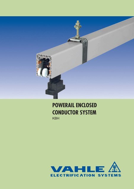
<strong>POWERAIL</strong> <strong>ENCLOSED</strong><strong>CONDUCTOR</strong> <strong>SYSTEM</strong>KBH
TYPES • TECHNICAL DATA • ORDER NUMBERSKBHFKBHSKBHF with spring loaded connectorsright sideleft sideKBHFType (1)HS with PESS without PENo.ofconductorsMax.continuous current A at 35 °C60% DF 80% DF 100% DFconductor cross sectionmm 2L1 L2 L3 N/5 (2) linecontrol-max.VoltageVKBHF 4/ 40...HS 4 52 45 40 3x10 10 - 600KBHF 4/ 40...SS control line 4 52 45 40 - - - 4x10 600KBHF 4/ 63...HS 4 81 70 63 3x14 14 - 600KBHF 4/100...HS 4 129 112 100 3x26 26 - 600KBHF 5/ 40...HS 5 52 45 40 3x10 10 10 600KBHF 5/ 40...SS control line 5 52 45 40 - - - 5x10 600KBHF 5/ 63...HS 5 81 70 63 3x14 14 14 600KBHF 5/100...HS 5 129 112 100 3x26 26 26 (3) 600KBHSKSGKBHS 4/ 40...HS 4 52 45 40 3x10 10 - 600KBHS 4/ 40...SS control line 4 52 45 40 - - - 4x10 600KBHS 4/ 63...HS 4 81 70 63 3x14 14 - 600KBHS 4/100...HS 4 129 112 100 3x26 26 - 600KBHS 4/125...HS 4 161 140 125 3x33 26 - - 600KBHS 4/160...HS 4 207 179 160 3x51 26 - 600KBHS 4/200...HS 4 258 224 200 3x70 42 - 600KBHS 5/ 40...HS 5 52 45 40 3x10 10 10 600KBHS 5/ 40...SS control line 5 52 45 40 - - - 5x10 600KBHS 5/ 63...HS 5 81 70 63 3x14 14 14 - 600KBHS 5/100...HS 5 129 112 100 3x26 26 26 (3) - 600KBHS 5/125...HS 5 161 140 125 3x33 26 26 (3) - 600KBHS 5/160...HS 5 207 179 160 3x51 26 26 (3) - 600KBHS 5/200...HS 5 258 224 200 3x70 42 26 (3) - 6004(1) ...Suffix types e.g. 2 m KBHF 4/63 with PE KBHF 4/63 - 2 HS Order-No. 600 012, shorter legths are made up fromthe next larger standard length.(2)In case of using a conductor as N see page 2.(3)5th. Conductor max. 80 A at 100% DF.
TYPES • TECHNICAL DATA • ORDER NUMBERKBHS with bolted jointsKBHFKBHSright sideleft sideLeakagedistancemmImpedanceat50 HZand20 °CΩ / 1000 mResistanceat20 °CΩ / 1000 mweightkg/mOrder-No. (1)A-AKBH 4-conductorsKBHF33 1,724 1,717 1,351 600 00•33 1,724 1,717 1,351 600 03•33 1,258 1,249 1,487 600 01•33 0,702 0,687 1,903 600 02•L1(2)54L3(4)safety-web33 1,724 1,717 1,452 600 10•33 1,724 1,717 1,452 600 13•33 1,258 1,249 1,622 600 11•33 0,702 0,678 2,142 600 12•70L2(1)(3)yellow(dark grey)green(dark grey)933 1,724 1,717 1,481 600 04•33 1,724 1,717 1,481 600 09•33 1,258 1,249 1,617 600 05•33 0,702 0,687 2,033 600 06•33 0,568 0,549 2,207 600 07•30 0,376 0,351 2,699 600 08•27 0,283 0,255 3,357 600 31•A-AKBH 5-conductorsL1(2)54L3(4)safety-webKBHSKSG33 1,724 1,717 1,614 600 14•33 1,724 1,717 1,614 600 19•33 1,258 1,249 1,784 600 15•33 0,702 0,687 2,304 600 16•33 0,568 0,549 2,479 600 17•30 0,376 0,351 2,970 600 18•27 0,283 0,255 3,628 600 32•70L2(1)9(3)yellow(dark grey)green(dark grey)Designation in brackets are valid if used as control line.• The last number of the order specifies the section length.Please suffix the order number with 1, 2, 3, 4.5Ground= PE
JOINTING MATERIAL • HANGERS • END CAPSKBHFKBHSJoint cap, self lockingready installedType weight kg Order-No.KVM 0,096 600 005Sliding hangerM8Fixpoint hanger142max.355835Sliding hanger at powerail sectionFixpoint hanger at powerail sectionType (1) weight kg Order-No.KGA 0,100 600 000KGA/K 0,100 600 397Typ (1) weight kg Order-No.KFA 0,132 600 007KFA/K 0,132 600 398End cap, left and right versionEnd cap ready installedType weight kg Order-No.KE 0,120 600 0086(1)..../K with stainless screwsAll steel metal components of the hangers are made of stainless.
BRACKETSview without -beamKBHFKBHS32L 25AM8support bracket30max. 37fixing claw suitablefor D = 6-15 mm45Dfixing clawA70121 +6-15170 +6-15Tow arm levelX15BR=10xDDview without -beamLX25M8max.48DA3032fixing claw suitablefor D = 15-25 mm45 BA121 +6-1515 170 +6-15Arrangement EHK with small fixing clawØ9Dsmall fixing clawSpecify dimension DAttention!Make sure that hoist wheels have enough clearance.Use small claw if necessary. Check -beam dimension D!- rail of EHK is identical to type S 1, Cat. 8 aOrder-No. Order-No.Type X L B max weight standard- with smallmm mm mm kg Version fixing clawEHK 250 250 350 170 1,070 251 600 251 720EHK 300 300 400 170 1,150 251 610 251 730EHK 400 400 500 170 1,300 251 620 251 740EHK 500 500 600 170 1,450 251 630 251 750EHK 600 600 700 170 1,600 251 640 251 760EHK 700 700 800 170 1,750 251 650 251 770EHK 750 750 850 170 1,820 251 660 251 780EHK 800 800 900 170 1,900 251 670 251 790Select next larger size bracket when youris more than 170 mm.-beam dimension B7
END FEEDS • LINE FEEDSKBHFKBHSEnd feed (40 - 63 A)13017End feed comes loose without powerail section.It can be mounted at the left or right hand side.Electrical connection with customer supplied cable shoes to M 6terminals.Max. connecting cross section 6 mm 289M4090M 32 (bottom-mounted)Typecable gland(dimensions see S. 10)weight kg Order-No.KKE 4/40-63 HS M 40 0,218 600 010KKE 5/40-63 HS M 40 0,230 600 107KKE 4/40 SS M 32 0,196 600 015KKE 5/40 SS M 32 0,208 600 108End feed (100 A)End feed comes loose without powerail section.It can be mounted at the left or right hand side.12020Electrical connection with customer supplied cable shoes to M 6terminals.Max. connecting cross section 35 mm 217785Type cable gland weight kg Order-No.(dimensions see S. 10)KKE 4/40-100 HS M 32 or M 50 (1) 0,600 600 422KKE 5/40-100 HS M 32 or M 50 (1) 0,640 600 423Line feed (40 - 63 A)KSE type comes loose without powerail section.It can be mounted at any joint.Electrical connection with customer supplied cable shoes to M 6terminals.50250140128Typecable gland(dimensions see S. 10)weight kg Order-No.KSE 4/ 40 HS M 25 0,756 600 030KSE 4/ 63 HS M 32 0,776 600 035KSE 5/ 40 HS M 25 0,812 600 037KSE 5/ 63 HS M 32 0,832 600 038KSE 4/ 40 SS M 25 0,756 600 028KSE 5/ 40 SS M 25 0,812 600 029Line feed (100 A)80250140KSE type comes loose without powerail section.It can be mounted at any joint.Electrical connection with customer supplied cable shoes to M 6terminals.158Typecable gland(dimensions see S. 10)weight kgOrder-No.KSE 4/100 HS M 50 0,908 600 036KSE 5/100 HS M 50 0,964 600 0398(1)Both cable glands are attached to the packing unit.
LINE FEEDSLine feed including 1 m section (40 - 100 A)a250140bElectrical connection with customer supplied cable shoes to M 6terminals..TypeMeasure Cable glanda b (dimensions see S.10)weight kgOrder-No.KEF 4/ 40 HS 50 128 M 25 2,099 600 197KEF 4/ 63 HS 50 128 M 32 2,255 600 199KEF 5/ 40 HS 50 128 M 25 2,256 600 205KEF 5/ 63 HS 50 128 M 32 2,446 600 207KEF 4/100 HS 80 158 M 50 2,803 600 201KEF 5/100 HS 80 158 M 50 3,098 600 209KEF 4/ 40 SS 50 128 M 25 2,099 600 195KEF 5/ 40 SS 50 128 M 25 2,256 600 203KBHFKBHSLine feed including 1 m section (125 A)Electrical connection with customer supplied cable shoes to M 6terminals.KBHSa250140bTypeMeasure Cable glanda b (dimensions see S.10)weight kg Order-No.KES 4/ 40 HS 50 128 M 25 2,229 600 221KES 4/ 63 HS 50 128 M 32 2,385 600 223KES 5/ 40 HS 50 128 M 25 2,413 600 229KES 5/ 63 HS 50 128 M 32 2,608 600 231KES 4/100 HS 80 158 M 50 2,933 600 225KES 4/125 HS 80 158 M 50 3,251 600 045KES 5/100 HS 80 158 M 50 3,260 600 233KES 5/125 HS 80 158 M 50 3,606 600 049KES 4/ 40 SS 50 128 M 25 2,229 600 219KES 5/ 40 SS 50 128 M 25 2,418 600 227Line feed including 1 m section (40 - 63 A)Electrical connection with customer supplied cable shoes to M 6terminals.25014012850TypeCable cross section in sqmm /DiaL1-L3 Earth Neutralweight kg Order-No.KELS 4/125 HS 35/16 25/10 - 8,560 600 069KELS 4/160 HS 50/18 25/10 - 9,784 600 075KELS 4/200 HS 70/21 35/11 - 11,400 600 385KELS 5/125 HS 35/16 25/10 9,372 600 077KELS 5/160 HS 50/18 25/10 25/15 10,596 600 079KELS 5/200 HS 70/21 35/11 12,212 600 387Terminal Box for KELS (125 -200 A)400“A”“B”120Electrical connection with customer supplied cable shoes.Clamping range 16-95 sqmm.View ,,A“ Input of the single cores of the KELS (a.m.)View „B“ with M 63 (Dimensions see page 10)Type for line feed weight kg Order-No.ZK 1 KELS 4/125 HS 5,030 600 389360 (1)200160ZK 2 KELS 4/160-200 HS 5,040 600 390ZK 3 KELS 5/125 HS 5,370 600 391ZK 4 KELS 5/160-200 HS 5,380 600 392(1)Fixing borings ø 7 mm at the bottom of the box.9
CURVES (1) • SEALING STRIPSKBHFKBHSCurvesProduction corresponding to customer drawing54safety-webMin. horizontal bending radiusmax.
HEATING(1)(1) Arrangement of heating cableWe recommend a heating system for outdoor installations and powerailsin humid plants. The heating consists of arrangement twoheating cables as per adjoining.Attention: Switch on heating system below + 5 °C.KBHFKBHSThe type of heating cable has to be calculated: heat output perheating cable between 20 - 25 W/m.For bigger heating distances the total length has to be devidedinto different heating sections.For smaller heating distances to feed with lower secondary voltagevia transformer.H3.0H2.0H1.44N(W/m)400V28262425222018H3.0Selection of heating cableH2.0H1.44H1.0H0.81H0.6H0.4830 40 50 60 70 80 90 100 110 120 130H1.0H0.81H0.6H0.48Heating capacity [Watt/m]: N’ =U = Supply voltage [Volt]R = Resistance of heating cable [Ohm/m]L = Lenght of heating section [m]U 2R·L 2N(W/m)230V28262422201825H3.0H3.0H2.0H2.0Installation ofheating cable:Outer diameter:H1.44H1.44H1.0H1.0H0.81H0.81H0.6H0.6H0.48H0.48l(m)H0.38H0.38H0.32H0.32H0.2H0.2H0.1530 40 50 60 70 80 90 100 110 120 130l(m)H0.15Heating resistor made of CrNi(different conductors)Isolation of heating cable PTFE (Teflon)nickel-plated copper nettingSheath PTFE-Isolation3,7 mm - 4,3 mmWire resistance data:heating cable: H 0,15 0,15 Ohm/mheating cable: H 0,20 0,20 Ohm/mheating cable: H 0,32 0,32 Ohm/mheating cable: H 0,38 0,38 Ohm/mheating cable: H 0,48 0,48 Ohm/mheating cable: H 0,60 0,60 Ohm/mheating cable: H 0,81 0,81 Ohm/mheating cable: H 1,00 1,00 Ohm/mheating cable: H 1,44 1,44 Ohm/mheating cable: H 2,00 2,00 Ohm/mheating cable: H 3,00 3,00 Ohm/mDeviations: ± 2,5 %Junction box for heating50250140128Type of cable gland Order-No.Junction box Measurements see page 9left end M 25 600 155right end M 25 600 156line feed 2x M 25 600 0651 set material for connecting clamps 195 291For each end feed box 2 sets of material for connecting ends arerequired.For line feed you need 4 sets of material for connection ends.Wiring layout for a heating section with junction boxes at each end.Feedlength L2 heating cablesone core cable > 2,5 mm 2by customermainsFeedSwitch gear assembly and temperature control unit as per customersinquiry. Fuses, cables etc. have to be provided by the customer.Order for 60 m powerail (example)1) 122 m heating cable type H 2,0(2 x 60 m and 2 x 1 m additional)Voltage 400 V, two heating circlesheating capacity as per above mentioned diagramm2 x 22 W/m at 60 m 2 x 22 W/m ~2640 W = 2,64 kW.2) 1x Junction box left end1x Junction box right end4) 4x sets of material for connection ends.11
RCONTACT SECTIONS, TURNTABLES AND SWITCHESKBHFKBHSContact section (1)w/o cond. Contact area(1) (1)w/o cond.line feed Powerail TrackTransfer funnelw/o cond.(1)Contact area(1)w/o cond.TurntableTransfer guide oblique cutTurntable frameTrackbaLine feedmax. 20 mmPowerailSliding switchTransfer guideTransfer guideaLine feedamax. 20 mm gapTrackTransfer guide oblique cutSwitch framePowerailMax. 20 mm air gap between transfer guides.Please submit drawings of transfer applications.Specify dimensions a, b, c, Rand angle ( = max. 50° )αc12(1)Contact sections must not be activated before collectors are fully engaged.Flexible tow arms (see page 18) for collectors are essential for contact sections.
140±10TRANSFER FUNNELS • TRANSFER GUIDESincluded powerail sectionsTransfer funnelPowerail should not be activated before the collectors carbonshave complete contact with the conductors.KBHFKBHS110205w/o cond. (2)Offset: ± 15 mm horizontal+ 10 mm verticalMax. speed for transfer 60 m/min.500Type (1) weight Order-No.kg left version right versionKET 4/ 40-125...HS 1,612 600 285 600 279KET 4/160...HS 1,724 600 286 600 280KET 4/200...HS 1,943 600 305 600 303KET 5/ 40-125...HS 1,720 600 288 600 282KET 5/160...HS 1,858 600 289 600 283KET 5/200...HS 2,128 600 306 600 304KET 4/ 40...SS 1,612 600 287 600 281KET 5/ 40...SS 1,720 600 290 600 28450±10Transfer guides, straight9070w/o cond.350Offset: ± 8 mm horizontal+ 3 mm verticalMax. speed for transfer 80 m/min.Type (1) weight Order-No.kg left version right versionKÜ 4/ 40-125...HS 1,348 600 261 600 255KÜ 4/160...HS 1,448 600 262 600 256KÜ 4/200...HS 1,640 600 309 600 307KÜ 5/ 40-125...HS 1,500 600 264 600 258KÜ 5/160...HS 1,625 600 265 600 259KÜ 5/200...HS 1,865 600 310 600 308KÜ 4/ 40...SS 1,348 600 263 600 257KÜ 5/ 40...SS 1,500 600 266 600 26090±10Transfer guides, oblique90110w/o cond.Offset: ± 8 mm horizontal+ 3 mm vertical350Measurements (oblique) and angleto be specified by customerMax. speed for crossover 80 m/min.Hinds for dimensioning the left-and right handversion refer to page 4 and 5.Type (1) weight Order-No..kg left version right versionKÜS 4/ 40-125...HS 1,312 600 273 600 267KÜS 4/160...HS 1,396 600 274 600 268KÜS 4/200...HS 1,560 600 317 600 315KÜS 5/ 40-125...HS 1,450 600 276 600 270KÜS 5/160...HS 1,555 600 277 600 271KÜS 5/200...HS 1,760 600 318 600 316KÜS 4/ 40...SS 1,312 600 275 600 269KÜD 5/ 40...SS 1,450 600 278 600 272(1) Add types e.g. KET 4/40-125…HSLeft hand version KET 4/40-125 L HS Order-No. 600 285(2) corresponding to the center of collector13
REMOVING SECTIONS • <strong>CONDUCTOR</strong> DEAD SECTIONSincluded 1 m sectionKBHFKBHSRemoving sectionwith special bolted joints for KBHF and KBHS on both ends.Assembly and disassembly of the collector is possible at the end ofthe track as well as at the removing section.For single collectorsType weight kg Order No.KAT 4/40-125 HS 3,450 600 165KAT 4/160 HS 3,802 600 166KAT 4/200 HS 4,494 600 327KAT 5/40-125 HS 3,781 600 167KAT 5/160 HS 4,133 600 168KAT 5/200 HS 4,825 600 328KAT 4/ 40 SS 3,450 600 169KAT 5/ 40 SS 3,781 600 170A1000AA-AcloseA-Aopen83For double collectors974By opening and closing the sliders at the bottom of the powerailhousing the collector can be mounted and demounted easily.Before opening disconnect mains.The removing section does not disconnect the powerailelectrically.110Type weight kg Order No.KATD 4/40-125 HS 4,044 600 175KATD 4/160 HS 4,396 600 176KATD 4/200 HS 5,088 600 329KATD 5/40-125 HS 4,375 600 177KATD 5/160 HS 4,727 600 178KATD 5/200 HS 5,419 600 330KATD 4/ 40 SS 4,044 600 179KATD 5/ 40 SS 4,375 600 180Conductor dead section30 mm isolating piecePicture shows a conductor dead section.Please advise us which conductors should be disconnected(see Page 5). The dead section comes factory assembled.Type Order No. Type Order No.KTL 1 600 298 KTI 1 600 293KTL 2 600 299 KTI 2 600 294KTL 3 600 300 KTI 3 600 295KTL 4 600 301 KTI 4 600 296KTL 5 600 302 KTI 5 600 29714
XXANTI - CONDENSATION SECTIONS • EXPANSION SECTIONincluded 1 m sectionAnti-Condensation Sectionswith special bolted joints for KBHF and KBHS at both ends.KBHFKBHS1000Application of Anti-Condensation SectionThe anti-condensation section will be used where Powerails arepassing from indoor to outdoor, preventing condensation of theoutside mounted Powerail. The warm air from indoors can escapethrough the anti condensation section.Type weight kg Order-No.KBT 4/40-125 HS 3,858 600 185KBT 4/160 HS 4,210 600 186KBT 4/200 HS 4,902 600 319KBT 5/40-125 HS 4,180 600 188KBT 5/160 HS 4,532 600 189KBT 5/200 HS 5,224 600 320KBT 4/ 40 SS 3,858 600 187KBT 5/ 40 SS 4,180 600 190End capAnti-condensationsectionLine feedPowerailThe anti-condensation section does not interrupt the Powerailelectrically.Crane runwayOutdoor0,5-1 mFix point hanger0,5-1 mX* *max. 75 mmax. 75 mIndoorOutdoorInstallationThe anti-condensation section is to be placed directly (0,5 m - 1 mmax.) at the transfer point from indoor to outdoor. See sketch.* For longer runs use Expansion section.Expansion Sectionwith special bolted joints for Powerail KBHF and KBHS(identical) including 1 m section.The Expansion sections are required to compensate the differentexpansions between copper conductors and steel- or concretestructures, in varying temperatures without interrupting electricalpower.Expansion joints are used when the Powerail length between feeds,curves, switches or other fix points is exceeding 20 m.Type weight kg Order-No.KD 4/ 40-125 HS 4,400 600 135KD 4/160 HS 4,752 600 136KD 4/200 HS 5,444 600 325KD 5/ 40-125 HS 4,895 600 138KD 5/160 HS 5,247 600 139KD 5/200 HS 5,939 600 326KD 4/ 40 SS 4,400 600 137KD 5/ 40 SS 4,895 600 140Max. length during differences in temperature:∆ t 90 °C (-30 °C to +60 °C) install one expansion joint per 100 m.An additional expansion joint every 100 m.End capCrane runwayFix point hangerXExpansionjoint sectionmax. lengthLine feed PowerailXmax. 75mAdditional feeds or current collectors are not required as theexpansion-sections do not interrupt electrical power.AssemblyThe gap dimension „a“ is 75 mm and is valid for an ambienttemperature of -10 °C to +35 °C during installation.Fix point hangerPowerailExpansion joint sectionTrackXXXX20 m to max. 100 m15
COLLECTORSKBHFKBHSCollector KSWmax. speed 150 m/min.Also for powerails with sealing strip up to 100 m/ min.170Connecting cables:for 25 A with 2,5 mm 2 /corefor 40 A with 4,0 mm 2 /corefor 60 A with 6,0 mm 2 /core1191 m long, longer cables on request.Cleaning collector on request.Order example for a 2 m long cableOrder-No. 600 096-2for collector KSW 4/40-2 HSTypePower ratingNo. ofweightat 60% DF conductorsca. ø of connecting- Travel speed kgA cables in mm in m/min.Order No.KSW 4/25-1 HS 25 4 12,5 150 0,552 600 095KSW 4/40-1 HS 40 4 14,5 150 0,656 600 096KSW 4/60-1 HS 60 (1) 4 17,0 150 0,797 600 066KSW 5/25-1 HS 25 5 13,5 150 0,634 600 098KSW 5/40-1 HS 40 5 16,0 150 0,771 600 099KSW 5/60-1 HS 60 (1) 5 19,5 150 0,945 600 413KSW 4/25-1 ST 25 4 11,0 150 0,472 600 097KSW 5/25-1 ST 25 5 12,0 150 0,534 600 100Collector KSWSmax. velocity 250 m/min.Also for powerails with sealing strip up to 100 m/ min.Connecting cable:for 25 A with 2,5 mm 2 /corefor 40 A with 4,0 mm 2 /corefor 60 A with 6,0 mm 2 /core1 m long, longer cables on request.Cleaning collector on request.Order example for a 2 m long cableOrder-No. 600 149-2for collector KSWS 5/40-2 HSTypePower ratingNo. ofweightat 60% DF conductorsca. ø of connecting- Travel speed kgA cables in mm in m/min.Order No.KSWS 4/25-1 HS 25 4 12,5 250 0,664 600 145KSWS 4/40-1 HS 40 4 14,5 250 0,768 600 146KSWS 4/60-1 HS 60 (1) 4 17,0 250 0,942 600 416KSWS 5/25-1 HS 25 5 13,5 250 0,724 600 148KSWS 5/40-1 HS 40 5 16,0 250 0,861 600 149KSWS 5/60-1 HS 60 (1) 5 19,0 250 1,035 600 417KSWS 4/25-1 ST 25 4 11,0 250 0,584 600 047KSWS 5/25-1 ST 25 5 12,0 250 0,624 600 15016(1)At 40% ED
60DOUBLE COLLECTORS • TOW ARMSDouble collectorsThe double collectors are supplied as an assembly kit consisting of:2 collectors (KSW) and a connecting bar with mounting material.For the collector KSWS there are no double collectors available 2 single collectors must be used instead.KBHFKBHSConnecting cable:for 50 A with (2x) 2,5 mm 2 /corefor 80 A with (2x) 4,0 mm 2 /corefor 120 A with (2x) 6,0 mm 2 /core1 m long, longer cables on request.Order example for 2 m long cablesOrder-No. 600 119-2for collector DKSW 5/80-2 HSTypePower ratingNo of-weightat 60% DFconductorsca. ø of connecting- Travel speed kgA cables in mm in m/min.Order-No.DKSW 4/ 50-1 HS 50 4 12,5 150 1,170 600 115DKSW 4/ 80-1 HS 80 4 14,5 150 1,378 600 116DKSW 4/120-1 HS 120 (1) 4 17,0 150 1,660 600 414DKSW 5/ 50-1 HS 50 5 13,5 150 1,334 600 118DKSW 5/ 80-1 HS 80 5 16,0 150 1,608 600 119DKSW 5/120-1 HS 120 (1) 5 19,0 150 1,956 600 415DKSW 4/ 50-1 ST 50 4 11,0 150 1,010 600 117DKSW 5/ 50-1 ST 50 5 12,0 150 1,134 600 120Tow arm with tube or square hollow profileTow arm for plane surfaceA-AVersion withsquare hollow profile(without adapter plate)by customerAAM8252slotted hole 9 x 301005310053A-Aversion with tube (2)19051 ± 10190234 to center of tubeType weight kg Order-No.MGU 0,550 600 334MGU/K 0,550 600 336Type weight kg Order-No.MGF 0,510 600 335MGF/K 0,510 600 337(1) At 40% ED(2) For assembly use enclosed adapter plate.17
FLEXIBLE TOW ARM • INSTALLATIONKBHFKBHSFlexible tow armfexible support type for single collector for installations withtransfer funnels type KET (see page 13) Measurements forinstallation see belowslotted hole 9 x 1833090138Type weight kg Order No.KFMH 1,200 600 333Flexible tow armArrangement of type KFMH with collector type KSW54L2L170AAfixing side6Ø10 6,3ca. 60 (1)301890966833013830518(1)To be fixed during installation.
EXAMPLES FOR ORDERING • SPARE PARTSExamples for orderingInstallation length of 64 m KBH... (configuration see page 4)KBHF 4/63 HS KBHF 5/100 HS KBHS 5/200 HSQuantity Article with end feed with line feed with line feedincluding. 1 m sectionType Order-No. Type Order-No. Type Order-No.16 Powerail, 4 m long KBHF 4/63-4 HS 600 014 KBHF 5/100-4 HS 600 124 - -15 Powerail, 4 m long - - - - KBHS 5/200-4HS 600 1841 Powerail, 3 m long - - - - KBHS 5/200-3HS 600 1831 End feed KKE 4/40-63 HS 600 010 - - - -1 Line feed - - KSE 5/100 HS 600 039 - -1 Line feed 1 m long - - - - KELS 5/160 HS 600 0791 End cap KE 600 008 - - - -2 End cap - - KE 600 008 KE 600 00815 Joint cap KVM 600 005 - - - -14 Joint cap - - KVM 600 005 - -16 Joint cap - - - - KVM 600 0051 Fix point hanger KFA 600 007 KFA 600 007 KFA 600 00732 Sliding hanger KGA 600 000 KGA 600 000 KGA 600 0001 Collector KSW 4/40-1 HS 600 096 KSW 5/40-1 HS 600 099 KSW 5/40-1 HS 600 0991 Tow arm MGU 600 334 MGU 600 334 MGU 600 334KBHFKBHSSpare part listPowerail KBHF KBHSOrder-No.Order-No.Joint cap (pair) 600 005 600 005Spring loaded connector 40 - 100 A 600 087 -Bolted joints 40 - 160 A - 234 685Bolted joints 200 A - 600 110Neoprene sealing strip, in pairs (max. length 40 m each) 235 794 235 794Coupling for sealing strip, in pairs (for lengths < 40 m each) 258 300 258 300Fixing clamp for sealing strip (1 per end) 600 354 600 354Mounting glider for sealing strip 600 109 600 109Feed terminal for end feed (40/63 A) 600 006 600 006Feed terminal for line feed (lateral) 600 017 600 017Feed terminal for line feed (on top,5th conductor) 600 016 600 016Spare part listCollector KSW/DKSW KSWSOrder-No.Order-No.Carbon brush phase (lateral) 600 088 600 088Carbon brush 5th conductor (top) 600 089 600 089Carbon brush ground (lateral PE) 600 090 600 090Carbon pressure spring (standard), suitable for all carbon brushes 600 338 600 338Connecting bar for double collector DKSW 600 105 -Assembly kit (to convert KSW KSWS) - 600 10619
EXAMPLES FOR ORDERINGInstallations with curves as per customer drawing350041,075 m powerail KBHF 4/63 consisting of:End feed45°XR = 2100Expansionjoint sectionPowerailX XL = 1648(1) Fixpoint hangerTrack1075according to installation temperaturefrom -10 °C to 35 °C90°29075R = 2700End capQtg Description Type Order No.7 Powerail, 4 m long KBHF 4/63-4 HS 600 0141 Powerail, 4 m long for KBHF 4/63-4 HS 600 0141 x 3500 mm short length2 Powerail, 3 m long for KBHF 4/63-3 HS 600 0131 x 2610 mm u. 1 x 2500 mm short length1 Powerail, 2 m long for horizontal curve KBHF 4/63-2 HS 600 01245°, R = 2100 mm, L = 1648 mm, SA2 Powerail., 3 m long for horizontal curve KBHF 4/63-3 HS 600 0132 x 45°, R = 2700 mm, L = 2121 mm, SI3 Surcharge for bending (horizontal) 600 0681 End feed KKE 4/40-63 HS 600 0101 Expansion section KD 4/40-125 HS 600 13511 Joint caps KVM 600 0054 Fixpoint hangers KFA 600 00724 Sliding hangers KGA 600 0001 End cap KE 600 0081 Collector KSW 4/40-1 HS 600 0961 Tow arm MGF 600 33541,075 m powerail KBHS 5/63 consisting of:Qtg Description Type Order No.8 Powerail, 4 m long KBHS 5/63-4 HS 600 1141 Powerail, 4 m long for KBHS 5/63-4 HS 600 1141 x 3500 mm short length2 Powerail, 3 m long for KBHS 5/63-3 HS 600 1131 x 2610 mm u. 1 x 2500 mm short lengths1 Powerail, 2 m for horizontal curve KBHS 5/63-2 HS 600 11245°, R = 2100 mm, L = 1648 mm, SA2 Powerail, 3 m for horizontal curve KBHS 5/63-3 HS 600 1132 x 45°, R = 2700 mm, L = 2121 mm, SI3 Surcharge for bending (horizontal) 600 0681 End feed KKE 5/40-63 HS 600 1071 Expansion section KD 5/40-125 HS 600 13811 Joint caps KVM 600 0054 Fixpoint hangers KFA 600 00724 Sliding hangers KGA 600 0001 End cap KE 600 0081 Collector KSW 5/40-1 HS 600 0991 Tow arm MGF 600 335XL = 4242(1)2610Rest of powerailto be installed with sliding hangers20
QUESTIONNAIRECompany:Date:Tel:E-Mail:Fax:Internet: (URL)1. Number of powerail installations:2. Type of equipment to be powered:3. Operating voltage:_________Volts, Phases:________, Frequency:______HzThree phase voltage: AC voltage: DC voltage:4. Track length:5. Number of powerails: (neutral: control rails: ground rail: )6. Mounted position of powerail:Powerail pendant, collector cable facing to the bottomSupport distance m (max. 2 m)Other:7. Number of consumers per system:8. Indoor: Outdoor:9. Other operating conditions (humidity, dust, chemical influence etc.)10. Ambient temperature: °C min. °C max.11. Position and number of feeding points and isolating sections (1) :12. Position and number of isolating sections (e.g. for maintenance):13. Brackets required: yes no c/c distance beam /Powerail14. How are the rails laid out? (Please provide sketch):15. Travel speed:16. Power consumption of the individual consumer loads:(Please consult table on reverse side)17. Max. Voltage drop from the powerail feed point to the consumer considering starting current:3% or % referring to nominal voltageRemarks:(1)For curved tracks, powerail with isolating sections etc., we require sketches to enable us to prepare a quotation. pto!Please copy and fill in the questionnaire.21
QUESTIONNAIREPaul Vahle GmbH & Co. KGD 59172 KamenFax 0 23 07 / 70 44 44E-Mail: export@vahle.deInternet: www.vahle.deDate:Motor dataHoist motorsAuxiliary hoistLong travelCross travelPowerkWCrane 1 Crane 2Nominal current Starting current Type of Power Nominal current Starting current Type ofA cos ϕ Motos (1) KWMotos (1)N %ED A cos ϕ A A cos ϕ N %ED A cos ϕ AMotor dataHoist motorsAuxiliary hoistLong travelCross travelPowerkWCrane 3 Crane 4Nominal current Starting current Type of Power Nominal current Starting current Type ofA cos ϕ Motos (1) KWMotos (1)N %ED A cos ϕ A A cos ϕ N %ED A cos ϕ AMark with * those motors which can run simultaneously.Mark with ∆ those motors which can start up simultaneously.(1) Use: K for squirrel cage motorS for slipring motorF for frequency controlled motorFurther remarks:Signature:22We reserve all rights to make alterations in the interests of further development.
APPLICATION PHOTOSCrane installations at company Rheinmetall Landsysteme (Kiel)23
Catalog Nr. 4e/E 2007MANAGEMENT<strong>SYSTEM</strong>DQS certified in accordance withDIN EN ISO 9001:2000OHSAS 18001 (Reg. no. 003140 QM OH)Products and ServiceCatalog no.Powerails1 aBattery Charging Systems1 bInsulated Powerails U 102 aInsulated Powerails U 20 - U 30 - U 402 bInsulated Powerails U 15 - U 25 - U 352 cAluminum Enclosed Conductor Systems LSV - LSVG3 aPowerail Enclosed Conductor Systems KBSL - KSL - KSLT4 aPowerail Enclosed Conductor Systems VKS - VKL4 bPowerail Enclosed Conductor Systems MKLD - MKLF - MKLS4 cPowerail Enclosed Conductor Systems VKS 104dPowerail Enclosed Conductor Systems KBH4eHeavy Enclosed Conductor Systems 5Trolley Wire and Accessories 6Cable Tenders 7Cable Carriers for tracks 8 aCable Carriers for Flatform Cables on beams 8 bFCable Carriers for Round Cables on beams 8 bRCable Carriers and Accessories for tracks 8 cConductor Cables and Fittings8 LSpring Operated Cable Reels9 a<strong>VAHLE</strong> POWERCOM ® Digital Transmission Systems 9 cCPS ® Contactless Power Supply 9 dSMG - Slotted Microwave Guide9 ePostion Encoding Systems9 fMotor Powered Cable Reels 10Installations/CommissioningSpare Parts/Maintenance Service0307 • Printed in Germany • 2507640/00E • DS • 2500 • 3/07PAUL <strong>VAHLE</strong> GMBH & CO. KG • Westicker Str. 52 • D 59174 KAMEN/GERMANY • TEL. (+49) 23 07/70 40Internet: www.vahle.de • E-Mail: info@vahle.de • FAX (+49) 23 07/70 44 44