TeSys contactors - MAXGroupOnline
TeSys contactors - MAXGroupOnline
TeSys contactors - MAXGroupOnline

You also want an ePaper? Increase the reach of your titles
YUMPU automatically turns print PDFs into web optimized ePapers that Google loves.
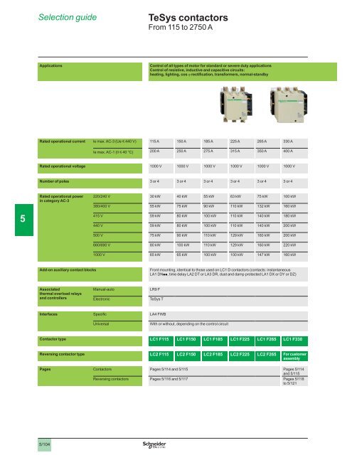
Selection guide<strong>TeSys</strong> <strong>contactors</strong>ApplicationsControl of all types of motor for standard or severe duty applicationsControl of resistive, inductive and capacitive circuits:heating, lighting, cosRated operational current y 115 A 150 A 185 A 225 A 265 A y 200 A 250 A 275 A 400 ARated operational voltage Number of poles 5Rated operational powerin category AC-3 Add-on auxiliary contact blocksppAssociatedthermal overload relaysand controllersInterfaces Contactor type LC1 F115 LC1 F150 LC1 F185 LC1 F225 LC1 F265 LC1 F330Reversing contactor type LC2 F115 LC2 F150 LC2 F185 LC2 F225 LC2 F265 For customerassemblyPages Contactors and 5/115 to 5/1215/104
400 A 500 A 780 A 800 A – – 750 A 1000 A 1500 A 1800 A500 A 700 A 1000 A 1600 A 1000 A 1700 A 2100 A 800 A 1250 A 2000 A 2750 A 1 to 4 1 to 4 1 to 4 1 to 4 – – – – – – – – 5 – – – – – – pp – – – – – – – – – –LC1 F400 LC1 F500 LC1 F630 LC1 F780 LC1 F800 LC1 F1700 LC1 F2100 LC1 BL LC1 BM LC1 BP LC1 BRFor customer assembly5/105
Characteristics<strong>TeSys</strong> <strong>contactors</strong>EnvironmentContactor type LC1 F115 LC1 F150 LC1 F185Rated insulation voltage V 1000 1000 1000 V 1500 1500 1500Rated impulse withstandvoltage Conforming to standardskV 8 8 8 Degree of protection Protective treatment Ambient air temperaturearound the device °C °C (1) °C Maximum operating altitude m Operating positions5Shock resistance (2)Vibration resistance (2) (1) In these conditions, it is recommended that LX9 F coils be used for contactor sizes F115to F225.(2) In the least favourable direction, without change of contact state (coil at Uc). Where higherresistance to mechanical shock is required, select shock-proof <strong>contactors</strong>. Please consult5/106
LC1 F225 LC1 F265 LC1 F330 LC1 F400 LC1 F500 LC1 F630 LC1 F780 LC1 F800 LC1 F1700 LC1 F21001000 1000 1000 1000 1000 1000 1000 1000 1000 10001500 1500 1500 1500 1500 1500 1500 1500 1500 15008 8 8 8 8 8 8 8 8 8 – – 5 5/107
Characteristics (continued)<strong>TeSys</strong> <strong>contactors</strong>Pole characteristicsContactor type LC1 F115 LC1 F150 LC1 F185Number of poles Rated operational currentyy A 115 150 185y A 200 250 275Rated operational voltage V 1000 1000 1000Frequency limits (1) Hz 16 …200 16 …200 16 …200Conventional thermal current y A 200 250 275Rated making capacityRated breaking capacityMaximum permissible currentyShort-circuit protectionby fusesUyIEC 60947-4-1A A IEC 60947-4-1For 10 s A 1100 1200 1500 A 640 700 920 A 520 600 740 A 400 450 500 A 400 A 125 160 200 A 200 200 A 200 250 5Average impedance per pole m Power dissipation per poleConnection W 5 8 12AC-1 W 15 22 25 2 2 2 mm mm 2 95 120 150 mm 2 95 120 150 mm Tightening torque N.m 10 18 18(1) Sine wave without interference. Above these values, please consult your Regional Sales(2) With set of right-angled connectors LA9 F2100 (see page 5/125).(3) Paralleling of poles must be carried out only in accordance with the fuse manufacturer'srecommendations.5/108
LC1 F225 LC1 F265 LC1 F330 LC1 F400 LC1 F500 LC1 F630 LC1 F780 LC1 F800 LC1 F1700 LC1 F2100 225 265 400 500 780 800 – – 400 500 700 1000 1250 1600 1000 1700 2100 (2)1000 1000 1000 1000 1000 1000 1000 1000 1000 100016 …200 16 …200 16 …200 16 …200 16 …200 16 …200 16 …200 16 …200 16 …200 16 …200 400 500 700 1000 1250 1600 1000 1700 2100 (2)1800 2200 2650 4200 5050 6250 5500 – –1000 1800 2400 4400 5600 4600 – –850 950 1700 2400 4600 – –560 620 900 1200 1500 2200 2600 – –440 480 750 1000 1200 1600 2200 1700 – –250 400 400 500 800 800 – – 500 500 800 800 1000 1000 – – 400 500 500 800 1000 (3) 1000 (3) (3) 0.28 0.26 0.18 0.12 0.10 0.12 0.10 0.1016 21 42 45 48 60 77 – – 44 65 88 120 250 120 200 20052 2 2 2 2 2 2 2 4 185 240 240 – – – – –185 240 – – – – – – – –10 10 10 10 10 12 12 12 12 58 58 58 58 5/109
Characteristics<strong>TeSys</strong> <strong>contactors</strong>Control circuit characteristics with LX1 or LX9 coilContactor type LC1 F115 LC1 F150 LC1 F185Rated control circuit voltage V 24…1000Control voltage limits y 0.85…1.1 Uc – –Average consumption a VA 550 550 805 VA – – –Cos VA 45 45 55 VA – – –Cos a VA 660 660 970 VA – – –Cos VA 55 55 66 VA – – –Cos 5Heat dissipation W 12…16 12…16 18…24Operating time (1) ms ms 5…15 5…15 7…15Mechanical durability at Uc 10 10 10Maximum operating rateyConnection 2400 2400 2400 mm 2 1/4 1/4 1/4 mm 2 1/4 1/4 1/4 mm 2 1/2.5 1/2.5 1/2.5 mm 2 1/4 1/4 1/4Tightening torque N.m 1.2 1.2 1.2Mechanical latching(1) The closing time "C" is measured from the moment the coil supply is switched on to initialcontact of the main poles. The opening time "O" is measured from the moment the coil supplyis switched off to the moment the main poles separate.(2) Control circuit characteristics with LX1 coil.5/110
LC1 F225 LC1 F265 LC1 F330 LC1 F400 LC1 F500 LC1 F630 LC1 F780 LC1 F800 LC1 F1700 LC1 F210024…1000 48…1000 48…1000 110…500 110…400 110…500 (2) 110…500 (2)0.85…1.1 Uc – –– 0.85…1.1 Uc 0.85…1.1 Uc 0.85…1.1 Uc 0.85…1.1 Uc 0.85…1.1 Uc 0.85…1.1 Uc 0.85…1.1 Uc– 0.25…0.5 Uc 0.2…0.4 Uc 805 – – – – – – – – –– 650 650 1075 1100 1650 2100 1700 2200 2200 0.9 0.9 0.9 0.9 0.9 0.9 0.9 0.9 0.955 – – – – – – – – –– 10 10 15 18 22 50 12 0.9 0.9 0.9 0.9 0.9 0.9 – 0.9 0.9970 – – – – – – – – –– 650 650 1075 1100 1650 2100 1700 2200 2200 0.9 0.9 0.9 0.9 0.9 0.9 0.9 0.9 0.966 – – – – – – – – –– 10 10 15 18 22 50 12 0.9 0.9 0.9 0.9 0.9 0.9 – 0.9 0.918…24 8 8 14 18 20 25 40…65 40…65 40…75 40…75 40…80 40…80 60…80 40…75 40…757…15 100…170 100…170 100…170 100…170 100…200 150…180 100…170 100…170510 10 10 10 10 5 5 5 5 52400 2400 2400 2400 2400 1200 600 600 600 6001/4 1/4 1/4 1/4 1/4 1/4 1/4 1/4 1/4 1/41/4 1/4 1/4 1/4 1/4 1/4 1/4 1/4 1/4 1/41/2.5 1/2.5 1/2.5 1/2.5 1/2.5 1/2.5 1/2.5 1/2.5 1/2.5 1/2.51/4 1/4 1/4 1/4 1/4 1/4 1/4 1/4 1/4 1/41.2 1.2 1.2 1.2 1.2 1.2 1.2 1.2 1.2 1.25/111
Characteristics<strong>TeSys</strong> <strong>contactors</strong>Control circuit characteristics with LX4 coilContactor type LC1 F115 LC1 F150 LC1 F185Rated control circuit voltage c V 24…460 24…460 24…460Control voltage limits 0.85…1.1 Uc 0.85…1.1 Uc 0.85…1.1 Ucy 0.15…0.2 Uc 0.15…0.2 Uc 0.15…0.2 UcAverage consumptionAverage operating timeat Uc (1)c W 560 560 800 W 4.5 4.5 5 ms ms Note: The arcing time depends on the circuit switched by the poles. For all normal 3-phaseapplications, the arcing time is less than 10 ms. The load is isolated from the supply after a timeequal to the sum of the opening time and the arcing time.Mechanical durability at Uc 10 10 10Maximum operating rate at 2400 2400 2400yCabling mm 2 1/4 1/4 1/4end mm 2 1/4 1/4 1/45 mm 2 1/4 1/4 1/4 mm 2 1/2.5 1/2.5 1/2.5 mm 2 1/4 1/4 1/4end mm 2 1/4 1/4 1/4Tightening torque N.m 1.2 1.2 1.2Mechanical latching(1) The operating times depend on the type of contactor electromagnet and its control mode. Theclosing time "C" is measured from the moment the coil supply is switched on to initial contactof the main poles. The opening time "O" is measured from the moment the coil supply isswitched off to the moment the main poles separate.5/112
LC1 F225 LC1 F265 LC1 F330 LC1 F400 LC1 F500 LC1 F630 LC1 F780 LC1 F800 LC1 F1700 LC1 F210024…460 24…460 24…460 48…440 48…440 48…440 110…440 110…400 110…440 110…4400.85…1.1 Uc 0.85…1.1 Uc 0.85…1.1 Uc 0.85…1.1 Uc 0.85…1.1 Uc 0.85…1.1 Uc 0.85…1.1 Uc 0.85…1.1 Uc 0.85…1.1 Uc 0.85…1.1 Uc0.15…0.2 Uc 0.15…0.2 Uc 0.15…0.2 Uc 0.2…0.4 Uc 800 750 750 1000 1100 1600 1900 2100 21005 5 5 6 6 9 12 10 10 40…50 40…50 50…60 50…60 60…70 70…80 60…80 50…60 50…60 40…65 40…65 45…60 45…60 40…50 40…50 45…60 45…60Note: The arcing time depends on the circuit switched by the poles. For all normal 3-phase applications. the arcing time is less than 10 ms. The load is isolatedfrom the supply after a time equal to the sum of the opening time and the arcing time.10 10 10 10 10 5 5 5 5 52400 2400 2400 2400 2400 1200 600 600 600 6001/4 1/4 1/4 1/4 1/4 1/4 1/4 1/4 1/4 1/41/4 1/4 1/4 1/4 1/4 1/4 1/4 1/4 1/4 1/41/4 1/4 1/4 1/4 1/4 1/4 1/4 1/4 1/4 1/41/2.5 1/2.5 1/2.5 1/2.5 1/2.5 1/2.5 1/2.5 1/2.5 1/2.5 1/2.51/4 1/4 1/4 1/4 1/4 1/4 1/4 1/4 1/4 1/451/4 1/4 1/4 1/4 1/4 1/4 1/4 1/4 1/4 1/41.2 1.2 1.2 1.2 1.2 1.2 1.2 1.2 1.2 1.2
References<strong>TeSys</strong> <strong>contactors</strong>3-pole <strong>contactors</strong>Standard power ratingsof 3-phase motors50-60 Hz in category AC-3Ratedoperationalcurrentin AC-3220 V 380 V660 V 440 V230 V 400 V 415 V 440 V 500 V 690 V 1000 V up toBasic reference,to be completed byadding the voltage code(2)cabling(1)WeightkW kW kW kW kW kW kW A kg 55 59 59 75 80 65 115 LC1 F115pp LC1 F22540 75 80 80 90 100 65 150 LC1 F150pp 55 90 100 100 110 110 100 185 LC1 F185pp 4.650 110 110 110 129 129 100 225 LC1 F225pp 4.75075 140 140 160 160 147 265 LC1 F265pp 7.440100 160 180 200 200 220 160 330 LC1 F330pp 8.600110 200 220 250 257 280 185 400 LC1 F400pp 9.100147 250 280 295 500 LC1 F500pp 200 400 400 450 450 630 LC1 F630pp 18.600LC1 F630220 400 425 425 450 475 450 780 LC1 F780pp 5250 450 450 450 450 475 450 800 LC1 F800pp 18.750Note: auxiliary contact blocks, modules and accessories: see pages 5/122 to 5/127.ordered separately, except on <strong>contactors</strong> LC1 F780 (see page 5/126).(2) Standard control circuit voltages (for other voltages, please consult your Regional SalesVolts a 24 48 110 115 120 208 220 230 240 380 400 415 440LC1 F115…F225 E5 F5 FE5 – – P5 U5 Q5 – – E6 F6 – – U6 Q6 – – R640 – E7 F7 FE7 P7 U7 Q7 R7LC1 F265…F33040 E7 F7 FE7 P7 U7 Q7 R7LC1 F400…F63040 – E7 F7 FE7 (3) P7 U7 Q7 R7LC1 F78040 – – F7 FE7 F7 P7 U7 Q7 R7LC1 F80040(4) – – – –Volts c 24 48 110 125 220 230 250 400 440LC1 F115…F330 – LC1 F400…F630 – – – LC1 F780 – – – – LC1 F800 – – – –(3) F7 for LC1 F630.(4) Coil LX4 F8pppp.5/114
References (continued)<strong>TeSys</strong> <strong>contactors</strong>2, 3 or 4-pole <strong>contactors</strong>Maximumcurrentin AC-1yNumber of polesBasic reference,to be completed byadding the voltage code (2)cabling (1)WeightAkg200 LC1 F115pp LC1 F18544 LC1 F1154pp 250 LC1 F150pp 4 LC1 F1504pp 275 LC1 F185pp 4.6504 LC1 F1854pp 5.450315 LC1 F225pp 4.7504 LC1 F2254pp 5.550350 LC1 F265pp 7.440LC1 F40044 LC1 F2654pp 8.540400 LC1 F330pp 8.6004 LC1 F3304pp 9.500500 2 LC1 F4002pp 8.000 LC1 F400pp 9.1004 LC1 F4004pp 10.2005700 2 LC1 F5002pp 9.750LC1 F6304 LC1 F500pp 4 LC1 F5004pp 12.9505686741000 2 LC1 F6302pp 15.500 LC1 F630pp 18.6004 LC1 F6304pp 21.5001250 2 LC1 F6302ppS011 15.500 LC1 F630ppS011 18.6004 LC1 F6304ppS011 21.500LC1 F17001600 LC1 F780pp 4 LC1 F7804pp 48.0005686751700 LC1 F1700 2100 (3) LC1 F2100 Note: auxiliary contact blocks, modules and accessories: see pages 5/122 to 5/127.be ordered separately (except LC1 F780, LC1 F1700 and LC1 F2100), see page 5/126.(2) Standard control circuit voltages, see previous page.(3) With set of right-angled connectors LA9 F2100 (see page 5/125).LC1 F21005/115
References 5<strong>TeSys</strong> <strong>contactors</strong> 5LC2 F1153-pole reversing <strong>contactors</strong> (1)Pre-wired power connectionsStandard power ratingsof 3-phase motors50/60 Hz in category AC-3Operationalcurrentin AC-3 Maximum Contactorsoperationalwithout coil (2)suppliedvoltage CompletereferenceFixing, cabling(3)WeightkW kW kW kW kW kW kW A V kg 55 59 59 75 80 65 115 1000 LC2 F115 7.56040 75 80 80 90 100 65 150 1000 LC2 F150 7.56055 90 100 100 110 110 100 185 1000 LC2 F185 10.100 110 110 110 129 129 100 225 1000 LC2 F225 14.20075 140 140 160 160 147 265 1000 LC2 F265 16.4805AccessoriesDescriptionPower terminalprotection shroudsFor reversing<strong>contactors</strong>QuantityrequiredReferenceWeightkg 2 LA9 F701 0.250 2 LA9 F702 0.250 2 LA9 F703 0.250Auxiliary contactblocks andadd-on modules– – to 5/1227(1) Fitted with a mechanical interlock without electrical interlocking. Order separately 2 auxiliarycontact blocks LAD Np1 to obtain electrical interlocking between the 2 <strong>contactors</strong>, see page5/123. For accessories, see pages 5/124 to 5/127.(2) Coils to be ordered separately:- a.c. supply, see pages 5/130 and 25/131,- d.c. supply, see page 5/133be ordered separately, see above.5/116
References (continued) 5<strong>TeSys</strong> <strong>contactors</strong> 5526098LC2 F18544-pole changeover contactor pairs (1)Pre-wired power connectionsUtilisation category AC-1Non inductive loadsMaximum operational current < 40 °CMaximumoperationalvoltageContactorssupplied withoutcoil (2)CompletereferenceWeightFixing, cabling (3)A V kg200 1000 LC2 F1154 8.860250 1000 LC2 F1504 8.860275 1000 LC2 F1854 12.100315 1000 LC2 F2254 15.200350 1000 LC2 F2654 19.480AccessoriesDescriptionPower terminalprotection shroudsFor changeoverpairsQuantityrequiredReferenceWeightkg 2 LA9 F706 0.250 2 LA9 F707 0.250 2 LA9 F708 0.2505Auxiliary contactblocks andadd-on modules– – to 5/1227(1) Fitted with a mechanical interlock without electrical interlocking. Order separately 2 auxiliarycontact blocks LAD Np1 to obtain electrical interlocking between the 2 <strong>contactors</strong>, see page5/123. For accessories, see pages 5/124 to 5/127.(2) Coils to be ordered separately:- a.c. supply, see pages 5/130 and 5/131,- d.c. supply, see page 5/133.be ordered separately, see above.5/117
Combinations 5<strong>TeSys</strong> <strong>contactors</strong> 5Horizontally mounted Mechanical interlocks Sets of power connectionsReversing <strong>contactors</strong>3-pole changeover contactorpairs (1)LA9 Fp970 (2) LA9 Fppp76 (2) LA9 Fppp82 (2)LC1 F115LC1 F150LC1 F185LC1 F225LC1 F265LC1 F330LC1 F400LC1 F500LC1 F630LC1 F800A1A2L121L243L356U2143VW56A1A2A1A21/L3211/L2431/L156L1 12/L122/L2L2432/L3L365A1A2Vertically mountedMechanical interlocks5LC1 F115LC1 F150LC1 F185LC1 F225LC1 F265LC1 F330LC1 F400LC1 F500LC1 F630LC1 F800LA9 FF4FLA9 FG4GLA9 FH4HLA9 FJ4JLA9 FK4KLA9 FL4LLC1 F780LA9 FX970(1) For 4-pole changeover contactor pairs, see pages 5/120 and 5/121.(2) Complete references: see page 5/119.5/118
References 5<strong>TeSys</strong> <strong>contactors</strong> 5Reversers assembled using 2 <strong>contactors</strong> of identical ratingContactor type Set of power connectionsMechanical interlock(1)ReferenceWeightkgKit reference WeightkgFor assembly of 3-pole reversing <strong>contactors</strong> for motor controlHorizontally mountedLC1 F115 LA9 FF976 0.600 LA9 FF970 0.060LC1 F150 LA9 F15076 0.600 LA9 FF970 0.060LC1 F185 LA9 FG976 0.780 LA9 FG970 0.060LC1 F225 LA9 F22576 1.500 LA9 FG970 0.060LC1 F265 LA9 FH976 1.500 LA9 FJ970 0.140LC1 F330 LA9 FJ976 2.100 LA9 FJ970 0.140LC1 F400 LA9 FJ976 2.100 LA9 FJ970 0.140LC1 F500 LA9 FK976 LA9 FJ970 0.140LC1 F630 or F800 LA9 FL976 LA9 FL970 0.150Vertically mountedLC1 F115 or F150 (2) – LA9 FF4F LC1 F185 (2) – LA9 FG4G LC1 F225 (2) – LA9 FG4G LC1 F265 or F330 (2) – LA9 FH4H 1.060LC1 F400 (2) – LA9 FJ4J 1.200LC1 F500 (2) – LA9 FK4K 1.200LC1 F630 or F800 (2) – LA9 FL4L 1.220LC1 F780 (3) – LA9 FX970 (3) 6.100For assembly of 3-pole changeover contactor pairs (4)Horizontally mountedLC1 F115 LA9 FF982 0.460 LA9 FF970 0.060LC1 F150 LA9 F15082 0.460 LA9 FF970 0.060LC1 F185 LA9 FG982 0.610 LA9 FG970 0.060LC1 F225 LA9 F22582 1.200 LA9 FG970 0.060LC1 F265 LA9 FH982 1.200 LA9 FJ970 0.140LC1 F330 LA9 FJ982 1.800 LA9 FJ970 0.140LC1 F400 LA9 FJ982 1.800 LA9 FJ970 0.140LC1 F500 LA9 FK982 LA9 FJ970 0.140LC1 F630 or F800 LA9 FL982 LA9 FL970 0.1505Vertically mountedLC1 F115 or F150 (2) – LA9 FF4F LC1 F185 (2) – LA9 FG4G LC1 F225 (2) – LA9 FG4G LC1 F265 or F330 (2) – LA9 FH4H 1.060LC1 F400 (2) – LA9 FJ4J 1.200LC1 F500 (2) – LA9 FK4K 1.200LC1 F630 or F800 (2) – LA9 FL4L 1.220LC1 F780 (3) – LA9 FX970 (3) 7.800(1) To order the 2 <strong>contactors</strong>: see pages 25/114 and 5/115. For the 2 auxiliary contact blocksLAD Np1 required to obtain electrical interlocking between the 2 <strong>contactors</strong>, see page 5/123For accessories, see pages 5/124 to 5/127(2) With the exception of <strong>contactors</strong> LC1 F780, all power connections are to be made by thecustomer.(3) Double mechanical interlock mechanism with 2 interlock connecting rods and 3 powerconnecting links.(4) For assembly of 4-pole changeover contactor pairs, see pages 5/120 and 5/121.5/119
Combinations 5<strong>TeSys</strong> <strong>contactors</strong> 5Horizontally mounted Mechanical interlocks Sets of power connectionsLC1 F1154LC1 F1504LC1 F1854LC1 F2254LC1 F2654LC1 F3304LC1 F4004LC1 F5004LC1 F6304LA9 Fp9704-pole changeover contactor pairs (1)LA9 Fppp77A1A21N211/L3431/L2568 71/L12/L1L1212/L2L2432/L3L3652NN87A1A2Vertically mountedLC1 F1154LC1 F1504LC1 F1854LC1 F2254LC1 F2654LC1 F3304LC1 F4004LC1 F5004LC1 F6304Mechanical interlocksAssembly A Assembly B Assembly CLA9 FF4FLA9 FH4HLA9 FX971LA9 FG4GLA9 FJ4JLA9 FK4KLA9 FL4L5LC1 F115 or F1154LC1 F150 or F1504LC1 F185 or F1854LC1 F225 or F2254LC1 F265 or F2654LC1 F330 or F3304LC1 F400 or F4004LC1 F500 or F5004LC1 F630 or F6304LC1 F800Assembly A Assembly B Assembly CLA9 FG4FLA9 FH4F, LA9 FH4GLA9 FJ4F, LA9 FJ4GLA9 FK4F, LA9 FK4GLA9 FL4F, LA9 FL4GLA9 FJ4HLA9 FK4H, LA9 FK4JLA9 FL4H, LA9 FL4J and LA9 FL4KLC1 F115 or F1154LC1 F150 or F1504LC1 F185 or F1854LC1 F225 or F2254LC1 F265 or F2654LC1 F330 or F3304LC1 F400 or F4004LC1 F500 or F5004LC1 F630 or F6304LC1 F800LA9 Fp4p4p : Important(1) For 3-pole changeover contactor pairs, see pages 5/118 and 5/119.5/120
References 5<strong>TeSys</strong> <strong>contactors</strong> 5Contactor pairs assembled using 2 <strong>contactors</strong> of identical ratingFor assembly of 4-pole changeover contactor pairs (1)Contactor type(2)Set of power connectionsReferenceWeightkgMechanical interlockKit reference WeightkgHorizontally mountedLC1 F1154 LA9 FF977 0.460 LA9 FF970 0.060LC1 F1504 LA9 F15077 0.460 LA9 FF970 0.060LC1 F1854 LA9 FG977 0.610 LA9 FG970 0.060LC1 F2254 LA9 F22577 1.200 LA9 FG970 0.060LC1 F2654 LA9 FH977 1.200 LA9 FJ970 0.140LC1 F3304 LA9 FJ977 1.800 LA9 FJ970 0.140LC1 F4004 LA9 FJ977 1.800 LA9 FJ970 0.140LC1 F5004 LA9 FK977 LA9 FJ970 0.140LC1 F6304 LA9 FL977 LA9 FL970 0.150Vertically mountedLC1 F1154 or F1504 (3) – LA9 FF4F LC1 F1854 (3) – LA9 FG4G LC1 F2254 (3) – LA9 FG4G LC1 F2654 or F3304 (3) – LA9 FH4H 1.060LC1 F4004 (3) – LA9 FJ4J 1.200LC1 F5004 (3) – LA9 FK4K 1.200LC1 F6304 (3) – LA9 FL4L 1.220LC1 F7804 (4) – LA9 FX971 (4) 7.800Contactor pairs assembled using 2 <strong>contactors</strong> of different ratingsFor assembly of 3 or 4-pole changeover contactor pairsContactor type(1)Mechanical interlockAt bottom At top Kit reference WeightkgVertically mountedLC1 F115 or F1154orLC1 F150 or F1504LC1 F185 or F1854orLC1 F225 or F2254LC1 F265 or F2654orLC1 F330 or F3304LC1 F185 or F1854 LA9 FG4F LC1 F225 or F2254 LA9 FG4F LC1 F265 or F2654 LA9 FH4F 0.870LC1 F330 or F3304 LA9 FH4F 0.870LC1 F400 or F4004 LA9 FJ4F LC1 F500 or F5004 LA9 FK4F 0.940LC1 F630, F6304 or F800 LA9 FL4F 0.940LC1 F265 or F2654 LA9 FH4G 0.860LC1 F330 or F3304 LA9 FH4G 0.860LC1 F400 or F4004 LA9 FJ4G 0.940LC1 F500 or F5004 LA9 FK4G 0.940LC1 F630, F6304 or F800 LA9 FL4G 0.950LC1 F400 or F4004 LA9 FJ4H LC1 F500 or F5004 LA9 FK4H LC1 F630, F6304 or F800 LA9 FL4H 1.140LC1 F400 or F4004 LC1 F500 or F5004 LA9 FK4J 1.200LC1 F630 or F6304 or F800 LA9 FL4J 1.210LC1 F500 or F5004 LC1 F630 or F6304 or F800 LA9 FL4K 1.2105For assembly of reversers using 3 <strong>contactors</strong>, vertically mounted(1) For assembly of 3-pole changeover contactor pairs, see pages 5/118 and 5/120.(2) To order the 2 <strong>contactors</strong>: see pages 5/114 and 5/115. For the 2 auxiliary contact blocksLAD Np1 required to obtain electrical interlocking between the 2 <strong>contactors</strong>, see page 5/123.For accessories, see pages 5/124 to 5/127.(3) All power connections are to be made by the customer.(4) Double mechanical interlock mechanism with 2 interlock connecting rods and 4 powerconnecting links.5/121
55T5/122
References 5<strong>TeSys</strong> <strong>contactors</strong> 5Instantaneous auxiliary contact blocksFor use in normal operating environmentsNumberofcontactsMaximum numberof blocks per contactorClip-on mountingComposition Reference Weightkg1 1 – – 1 – LAD N10 0.020– – – 1 LAD N01 0.0202 2 – – 1 1 LAD N11 – – 2 – LAD N20 – – – 2 LAD N02 4 2 – – 2 2 LAD N22 0.050– – 1 LAD N13 0.050– – 4 – LAD N40 0.050– – – 4 LAD N04 0.050– – 1 LAD N31 0.050– – 2 2 (1) LAD C22 0.050With terminal referencing conforming to EN 500122 2 – – 1 1 LAD N11P – – 1 1 LAD N11G 4 2 – – 2 2 LAD N22P 0.050– – 2 2 LAD N22G 0.050Instantaneous auxiliary contact blocks for connection by lugs6LAD N11LAD N116.5Instantaneous auxiliary contact blocks with dust and dampprotected contactsRecommended for use in particularly harsh industrial environmentsNumberofcontactsMaximum number ofblocks per contactorClip-on mountingComposition Reference Weightkg2 2 2 – – – LA1 DX20 0.0402 2 (2) – – LA1 DY20 0.040rAvailable 2 nd half 2009.4 2 2 – 2 – LA1 DZ40 0.0502 – 1 1 LA1 DZ31 0.050Time delay auxiliary contact blocksNumberofcontacts1 N/O+1 N/CMaximum number of Time delay Reference Weightblocks per contactorClip-on mounting Type Rangeskg2 0.1(3) LAD T0 0.0600.1 LAD T2 0.06010180 LAD T4 0.0601(4) LAD S2 0.060 0.1(3) LAD R0 0.0600.1 LAD R2 0.06010180 LAD R4 0.060Interface for PLC controlType of I/O Reference Weightc akgLA4 FSREr –(1) Including 1 N/O + 1 N/C make before break(3) With extended scale from 0.1 to 0.6 s.(4) With switching time of 40 ms ± 15 ms between opening of the N/C contact and closing of theN/O contact.
References 5<strong>TeSys</strong> <strong>contactors</strong> 5LA9 D09981LA4 FpppSuppressor blocksRC circuits b b b Mounting Uc Reference Weightkg a24 LA4 FRCE 0.04050 LA4 FRCF 0.040127 LA4 FRCP 0.040265 LA4 FRCV 0.040Suppressor block bracket LA9 D09981 0.010Varistorsb b a orc 24 LA4 FVE 0.04050 LA4 FVF 0.040127 LA4 FVP 0.040265 LA4 FVV 0.0405LA9 Fp602LA9 Fp601DZ3 FA3Diodesb b b c 24 LA4 FDE 0.04055 LA4 FDF 0.040125 LA4 FDP 0.040280 LA4 FDV 0.040Bidirectional peak limiting diodesb b a orc 24 LA4 FTE 0.04050 LA4 FTF 0.040127 LA4 FTP 0.040265 LA4 FTV 0.040Connection accessoriesFor use on 4-pole <strong>contactors</strong> Set of 4 links WeightSet reference kgLinks for parallel connection of poles LA9 FF602 0.200 LA9 FG602 LA9 FH602 1.000 LA9 FK602 1.750 LA9 FL602 Links for “star” connection of 3 poles LA9 FF601 LA9 FG601 0.050 LA9 FH601 0.120 LA9 FK601 0.180 LA9 FL601 0.550Control circuit voltage take-off from power terminalsFor use with <strong>contactors</strong> Mounted onbolt sizeSold inlots ofUnitreferenceWeightkg 10 DZ3 FA3 0.004 10 DZ3 GA3 0.004 10 DZ3 HA3 0.006 10 DZ3 JA3 0.0095/124
References (continued) 5<strong>TeSys</strong> <strong>contactors</strong> 5Right-angled connectorsFor <strong>contactors</strong> or thermal overload relaysFor use with With connector plates Set of 3 connectorsContactors Thermal overloadSet reference Weightrelays (1)Width Type kg p Rear LA9 FF981 0.060LA9 Fp981F185F400pp LA9 FF979 0.240 LA9 FF980 0.150 Rear LA9 FG981 0.080 LA9 FG979 LA9 FG980 0.200p Rear LA9 FJ981 LA9 FJ979 0.750LA9 Fp979pp LA9 FJ980 0.490 Rear LA9 FK981 0.480 LA9 FK979 0.920510487F800 LA9 FK980 0.800p Rear LA9 FL981 1.210 LA9 FL979 2.570LA9 FL980 LA9 FL980 For use withWith connector Set of 6 connectorsContactors Thermal overload platesSet reference Weightrelays (1)Width Type kgF2100– Rear LA9 F2100 9.5505510487LA9 F2100Connection accessoriesFor reversing <strong>contactors</strong> or "star-delta" <strong>contactors</strong> combined with a thermaloverload relayFor use withContactorsand F185and F265Thermal overloadrelays (1)pppp69Width ofconnector platesSet of 3 busbarsSet referenceWeightkg LA7 F401 0.110pp LA7 F402 0.110pppp79 LA7 F407 0.160 LA7 F403 0.160 LA7 F404 0.160and F400pp79 LA7 F404 0.160 p LA7 F404 0.160F800pp79p81p LA7 F405 0.270 LA7 F406 0.600(1) For protection relays class 10, replace the p with a 3 and for class 20, replace the p with a 5.5/125
References (continued) 5<strong>TeSys</strong> <strong>contactors</strong> 5Insulated terminal blocksFor use on3-pole <strong>contactors</strong>ConnectionLC1 F115, F150, F185 2or 2TighteningtoolSet of 2 blocks WeightSet reference kgLA9 F103 0.560LA9 F103Power terminal protection shroudsFor use on2, 3 and 4-pole <strong>contactors</strong>Number ofshrouds per setSet referenceWeightkgLC1 F115 6 LA9 F701 0.250LC1 F150, F185 6 LA9 F702 0.250LC1 F225, F265, F330, F400 and F4002F500 and F50026 LA9 F703 0.250LC1 F630, F6302 and F800 6 LA9 F704 0.250LC1 F1154 8 LA9 F706 LA9 F701LC1 F1504 and F1854 8 LA9 F707 LC1 F2254, F2654, F3304, F4004, F5004 8 LA9 F708 5LC1 F6304 8 LA9 F709 5/126
References 5<strong>TeSys</strong> <strong>contactors</strong> 5LA5 FG431569556 569555LA5 F40050Sets of contactsFor contactor Type ReplacementforReferenceWeightkg2-pole LA5 F400802 LA5 F500802 1.950 LA5 F630802 4.700 LA5 F630802S011 4.8003-pole LA5 FF431 0.270 LA5 FG431 LA5 FH431 0.660 LA5 F400803 2.000 LA5 F500803 2.950 LA5 F630803 6.100 LA5 F780801 (1) 4.700 LA5 F780803 LA5 F800803 6.100 LA5 F630803S011 6.2004-pole LA5 FF441 LA5 FG441 0.465 LA5 FH441 0.880 LA5 F400804 2.700 LA5 F500804 LA5 F630804 8.150 LA5 F780801 (1) 4.700 LA5 F780804 LA5 F630804S011 8.400Arc chambersFor contactor Type Replacement ReferenceforWeightkg2-pole LA5 F400250 0.870 LA5 F500250 1.250 LA5 F630250 2.100 LA5 F630250 2.1003-pole LA5 F11550 0.490 LA5 F15050 0.490 LA5 F18550 0.670 LA5 F22550 0.670 LA5 F26550 0.920 LA5 F33050 LA5 F40050 LA5 F50050 1.850 LA5 F63050 LA5 F780150 (1) 2.100 LA5 F80050 LA5 F63050 LA5 F170050 (2) LA5 F210050 (2) 5LA5 F2100504-pole LA5 F115450 0.660 LA5 F150450 0.660 LA5 F185450 0.910 LA5 F225450 1.000 LA5 F265450 1.220 LA5 F330450 1.740 LA5 F400450 (3) 1.740 LA5 F500450 (3) 2.500 LA5 F630450 (4) 4.200 LA5 F780150 (1) 2.100 LA5 F630450 4.200(1) Comprising 2 identical items per pole.(2) Comprising three 2-pole arc chambers.(3) Comprising two 2-pole arc chambers.(4) Comprising single-pole arc chambers.5/127
5References 5LA9 Fp4p4p<strong>TeSys</strong> <strong>contactors</strong> 5Mechanical interlock kitsContactor type (1) Mechanical interlock (2)Top Middle Bottom Kit reference (3) WeightkgF1154 or F1504F1854 or F2254or F4004or F5004F1154 or F1504F1154 or F1504F1854 or F2254F1154 or F1504F1854 or F2254F1154 or F1504F1854 or F2254or F4004F1154 or F1504F1854 or F2254or F4004or F5004F1154 or F1504F1154 or F1504F1154 or F1504F1854 or F2254F1154 or F1504F1154 or F1504F1854 or F2254F1154 or F1504F1854 or F2254F1154 or F1504F1154 or F1504F1854 or F2254F1154 or F1504F1854 or F2254F1154 or F1504F1854 or F2254or F4004F1154 or F1504F1154 or F1504F1854 or F2254F1154 or F1504F1854 or F2254F1154 or F1504or F4004F1154 or F1504LA9 FF4F4F 0.554LA9 FG4F4F 0.559LA9 FG4G4F 0.559LA9 FG4G4G 0.562LA9 FH4F4FLA9 FH4G4FLA9 FH4G4GLA9 FH4H4F 1.524LA9 FH4H4G 1.527LA9 FH4H4H 1.684LA9 FJ4F4F 1.421LA9 FJ4G4F 1.424LA9 FJ4G4G 1.428LA9 FJ4H4F 1.595LA9 FJ4H4G 1.598LA9 FJ4H4H 1.755LA9 FJ4J4F 1.666LA9 FJ4J4G 1.669LA9 FJ4J4H 1.829LA9 FJ4J4J 1.890LA9 FK4F4F 1.421LA9 FK4G4F 1.424LA9 FK4G4G 1.428LA9 FK4H4F 1.595LA9 FK4H4G 1.598LA9 FK4H4H 1.755LA9 FK4J4F 1.666LA9 FK4J4G 1.669LA9 FK4J4H 1.829LA9 FK4J4J 1.896LA9 FK4K4F 1.666(1) To order the 3 <strong>contactors</strong>, see pages 5/114 and 5/115. For auxiliary contact blocks LAD N02used for electrical locking, see page 5/123. For accessories, see pages 5/124 to 5/127.(2) Minimum distances between <strong>contactors</strong>, see page 5/129.(3) The kit contains the lever arms, the 2 x Ø 8 mm rods and all parts required for assembly.5/128
References (continued) 5<strong>TeSys</strong> <strong>contactors</strong> 5LA9 Fp4p4pMechanical interlock kits (continued)Contactor type (1) Mechanical interlock (2)Top Middle Bottom Kit reference (3) Weightkgor F5004(continued)or F5004F1154 or F1504F1854 or F2254or F4004or F5004F1854 or F2254or F4004or F5004F1154 or F1504F1154 or F1504F1854 or F2254F1154 or F1504F1854 or F2254F1154 or F1504F1854 or F2254or F4004F1154 or F1504F1854 or F2254or F4004or F5004F1154 or F1504F1854 or F2254or F4004or F5004LA9 FK4K4G 1.669LA9 FK4K4H 1.825LA9 FK4K4J 1.896LA9 FK4K4K 1.896LA9 FL4F4F 1.428LA9 FL4G4FLA9 FL4G4GLA9 FL4H4F 1.602LA9 FL4H4G 1.606LA9 FL4H4H 1.751LA9 FL4J4FLA9 FL4J4G 1.676LA9 FL4J4HLA9 FL4J4JLA9 FK4K4F 1.666LA9 FK4K4G 1.669LA9 FK4K4H 1.825LA9 FK4K4J 1.896LA9 FK4K4K 1.896LA9 FL4L4F 1.680LA9 FL4L4GLA9 FL4L4H 1.910LA9 FL4L4J 1.896LA9 FL4L4K 1.896LA9 FL4L4L 1.920(1) To order the 3 <strong>contactors</strong>, see pages 5/114 and 5/115. For auxiliary contact blocks LAD N02used for electrical locking, see page 5/123. For accessories, see pages 5/124 to 5/127.(2) Minimum distances between <strong>contactors</strong>.This is the distance, in mm, between the centres of two adjacent <strong>contactors</strong> (between the top andmiddle <strong>contactors</strong> or between the middle and bottom <strong>contactors</strong>).5ContactorBottom or topMiddleLC1 F115or F150LC1 F185or F225LC1 F265or F330LC1 F400 LC1 F500 LC1 F630or F800 200 210 240 250 270 210 220 250 250 270 240 250 250 260 280 250 250 260 260 280 270 270 280 280 (3) The kit contains the lever arms, the 2 x Ø 8 mm rods and all parts required for assembly.5/129
References<strong>TeSys</strong> <strong>contactors</strong>5LX1 FFpppLX1 FGpppReferencesyy2400.Control circuitvoltageUc - 50 Hz Uc - 60 HzAverage Inductance Voltageresistance at of closed code20 °C 10 % circuitReferenceWeightV V H kgFor <strong>contactors</strong> LC1 F115 and LC1 F15024 – 0.27 0.04 B5 LX1 FF024 42 – 0.94 D5 LX1 FF042 – 48 0.78 0.11 E6 LX1 FF040 48 – 1.17 0.16 E5 LX1 FF048 – 110 4.55 0.59 F6 LX1 FF092 – 120 4.77 0.64 G6 LX1 FF095 110 – 0.86 F5 LX1 FF110 115 – 0.86 FE5 LX1 FF110 127/132 – 9.14 1.15 G5 LX1 FF127 – 200/208 14.5 1.87 L6 LX1 FF162 – 220 18.4 M6 LX1 FF184 – 240 18.9 2.5 U6 LX1 FF187 220 265/277 28.1 M5 LX1 FF220 230 – 28.1 P5 LX1 FF220 240 – 4.1 U5 LX1 FF240 – 380 57.2 7.05 Q6 LX1 FF316 – 440 72.6 9.21 R6 LX1 FF360 380 460/480 86.9 Q5 LX1 FF380 400 – 86.9 V5 LX1 FF380 415 – 95.1 12 N5 LX1 FF415 500 – 141 17 S5 LX1 FF500 – 660 172 Y6 LX1 FF550 660/690 – 254 28.9 Y5 LX1 FF660 – 1000 414 48.9 – LX1 FF850 1000 – 610 68.5 – LX1 FF1000 --For <strong>contactors</strong> LC1 F185 and LC1 F22524 – 0.18 B5 LX1 FG024 0.55042 – 0.57 0.09 – LX1 FG042 0.550– 48 0.47 0.08 E6 LX1 FG040 0.55048 – 0.71 0.12 E5 LX1 FG048 0.550– 110 2.74 0.44 F6 LX1 FG092 0.550– 115/120 2.87 0.49 G6 LX1 FG095 0.550110 – 4.18 0.65 F5 LX1 FG110 0.550115 – 4.18 0.65 FE5 LX1 FG110 0.550127/132 – 0.86 G5 LX1 FG127 0.550– 200/208 8.8 1.41 L6 LX1 FG162 0.550– 220 11.1 1.8 M6 LX1 FG184 0.550– 240 11.4 1.87 U6 LX1 FG187 0.550220 265/277 16.5 2.59 M5 LX1 FG220 0.550230 – 16.5 2.59 P5 LX1 FG220 0.550240 – 20.1 U5 LX1 FG240 0.550– 380 Q6 LX1 FG316 0.550– 440 6.94 R6 LX1 FG360 0.550380 460/480 7.75 Q5 LX1 FG380 0.550400 – 7.75 V5 LX1 FG380 0.550415 – 9.06 N5 LX1 FG415 0.550500 – 82.7 12.8 S5 LX1 FG500 0.550– 660 Y6 LX1 FG550 0.550660/690 – 154 21.8 Y5 LX1 FG660 0.550– 1000 249 – LX1 FG850 0.5501000 – 51.6 – LX1 FG1000 0.550--
References<strong>TeSys</strong> <strong>contactors</strong>LX1 FHppp2LX1 FJpppReferencesy 7.yy 2400.ControlcircuitvoltageUcAverage resistanceat 20 °C 10 %InrushSealedInductanceof closedcircuitVoltagecodeReferenceWeightV H kgFor <strong>contactors</strong> LC1 F265 and LC1 F33024 0.8 20 (1) B7 LX1 FH0242 0.75048 2.96 67 (1) E7 LX1 FH0482 0.750110 18.7 440 (1) F7 LX1 FH1102 0.750115 18.7 440 (1) FE7 LX1 FH1102 0.750120/127 22.9 (1) G7 LX1 FH1272 0.750200/208 58.4 (1) L7 LX1 FH2002 0.750220 70.6 1578 (1) M7 LX1 FH2202 0.750230 70.6 1578 (1) P7 LX1 FH2202 0.750240 87.94 1968 (1) U7 LX1 FH2402 0.750277 2444 (1) W7 LX1 FH2772 0.750380 217 (1) Q7 LX1 FH3802 0.750400 217 (1) V7 LX1 FH3802 0.750415 217 (1) N7 LX1-FH3802 0.750440 265 (1) R7 LX1 FH4402 0.750480/500 (1) S7 LX1 FH5002 0.750600/660 296 10 245 (1) X7 LX1 FH6002 0.7501000 696 25 880 (1) – LX1 FH10002 0.750- - For contactor LC1 F40048 1.6 29.5 0.18 E7 LX1 FJ048 1.000110/120 9.8 F7 LX1 FJ110 1.000115 9.8 FE7 LX1 FJ110 1.000120/127 12.8 280 1.75 G7 LX1 FJ127 1.000200/208 815 4.1 L7 LX1 FJ200 1.000220 5.1 M7 LX1 FJ220 1.000230 5.1 P7 LX1 FJ220 1.000240 47.5 6.4 U7 LX1 FJ240 1.000265/277 61 1700 8.1 W7 LX1 FJ280 1.000380 120 15.8 Q7 LX1 FJ380 1.000400 120 15.8 V7 LX1 FJ380 1.000415 145 4070 19.4 N7 LX1 FJ415 1.000440 145 4070 19.4 R7 LX1 FJ415 1.000500 190 4980 25.5 S7 LX1 FJ500 1.000550/600 27.4 X7 LX1 FJ600 1.0001000 720 19 420 84.6 – LX1 FJ1000 1.000 - - 5
References (continued)<strong>TeSys</strong> <strong>contactors</strong>5LX1 FKpppLX1 FLpppReferences (continued)y 7.ControlcircuitvoltageUcAverage resistanceat 20 °C 10 %Inrush SealedInductanceof closedcircuitVoltagecodeReferenceWeightV H kgFor contactor LC1 F50048 1.9 0.19 E7 LX1 FK048 1.150110/120 9.55 260 1.25 F7 LX1 FK110 1.150115 9.55 260 1.25 FE7 LX1 FK110 1.150120/127 11.5 1.5 G7 LX1 FK127 1.150200/208 29 L7 LX1 FK200 1.150220 915 4.55 M7 LX1 FK220 1.150230 915 4.55 P7 LX1 FK220 1.150240 44.5 1160 5.75 U7 LX1 FK240 1.150265/277 56.5 1490 W7 LX1 FK280 1.150380 112 2980 14.7 Q7 LX1 FK380 1.150400 112 2980 14.7 V7 LX1 FK380 1.150415 18.4 N7 LX1 FK415 1.150440 18.4 R7 LX1 FK415 1.150500 172 4590 22.8 S7 LX1 FK500 1.150550/600 5660 X7 LX1 FK600 1.1501000 679 16 960 72 – LX1 FK1000 1.150- - yy 2400.For contactor LC1 F63048 1.1 17.1 0.09 E7 LX1 FL048 1.500110/120 6.45 165 1.85 F7 LX1 FL110 1.500115 6.45 165 1.85 FE7 LX1 FL110 1.500127 8.1 205 1.05 G7 LX1 FL127 1.500200/208 20.5 605 2.65 L7 LX1 FL200 1.500220 25.5 M7 LX1 FL220 1.500230 25.5 P7 LX1 FL220 1.500240 25.5 U7 LX1 FL220 1.500265/277 900 4.1 W7 LX1 FL260 1.500380 78 10.5 Q7 LX1 FL380 1.500400 78 10.5 V7 LX1 FL380 1.500415 96 2960 N7 LX1 FL415 1.500440 96 2960 R7 LX1 FL415 1.500500 120 16.5 S7 LX1 FL500 1.500550/600 155 4560 19.5 X7 LX1 FL600 1.5001000 474 12 880 56.2 – LX1 FL1000 1.500- - y
References (continued)<strong>TeSys</strong> <strong>contactors</strong>References (continued)y 7.ControlcircuitvoltageUcAverage resistanceat 20 °C 10 %Inrush SealedInductanceof closedcircuitVoltagecodeReferenceWeightV H kgFor contactor LC1 F780110/120 4.95 (2) (2) 0.21 F7 LX1 FX110 (1) 115 4.95 (2) (2) 0.21 FE7 LX1 FX110 (1) 127 6.1 (2) 280 (2) 0.26 G7 LX1 FX127 (1) 200/208 15.5 (2) 750 (2) 0.66 L7 LX1 FX200 (1) 220 19.5 (2) 920 (2) 0.82 M7 LX1 FX220 (1) 230 19.5 (2) 920 (2) 0.82 P7 LX1 FX220 (1) 240 19.5 (2) 920 (2) 0.82 U7 LX1 FX220 (1) 265/277 29.8 (2) (2) 1.25 W7 LX1 FX280 (1) 380 60.9 (2) 2780 (2) Q7 LX1 FX380 (1) 400 60.9 (2) 2780 (2) V7 LX1 FX380 (1) 415/480 (2) (2) 2.8 N7 LX1 FX415 (1) 440 (2) (2) 2.8 R7 LX1 FX415 (1) 500 92 (2) 4180 (2) S7 LX1 FX500 (1) - yFor contactor LC1 F800Control circuitvoltageUcVVoltagecodeReference(3)CoilReferenceWeight110/127 FE7 DR5 TE4U LX4 F8FW 1.650220/240 P7 DR5 TE4U LX4 F8MW 1.650380/440 V7 DR5 TE4S LX4 F8QW 1.650y- kg5ControlcircuitvoltageUcAverage resistanceat 20 °C 10 %InrushSealedInductanceof closedcircuitVoltagecodeReferenceWeightV H kgFor <strong>contactors</strong> LC1 F1700 and LC1 F2100110 5.92 106 0.72 F7 LX1 FK065 (4) 1.150120 5.92 106 0.72 G7 LX1 FK070 (4) 1.150220 9.55 260 1.25 M7 LX1 FK110 (4) 1.150230 9.55 260 1.25 P7 LX1 FK110 (4) 1.150240 11.5 1.50 U7 LX1 FK127 (4) 1.150277 16.5 420 2.25 W7 LX1 FK140 (4) 1.150380 29 Q7 LX1 FK200 (4) 1.150400 29 V7 LX1 FK200 (4) 1.150415 915 4.55 N7 LX1 FK220 (4) 1.150440 915 4.55 R7 LX1 FK220 (4) 1.150500 44.5 1160 5.75 S7 LX1 FK240 (4) 1.150- y(1) Reference of set of 2 identical coils, to be connected in series.(2) Value for the 2 coils in series.(4) Order 2 coils and connect them in series.
References<strong>TeSys</strong> <strong>contactors</strong> (1)5LX9 FFpppLX9 FGpppReferencesy 7.ControlcircuitvoltageUcAverage resistanceat 20 °C 10 %Inrush SealedInductanceof closedcircuitVoltagecodeReferenceWeightV H kgFor <strong>contactors</strong> LC1 F115 and LC1 F15048 80.2 E7 LX9 FF048 110 14.8 579 2.08 F7 LX9 FF110 115 14.8 579 2.08 FE7 LX9 FF110 120/127 19 746 2.65 G7 LX9 FF127 208 45 1788 5.95 L7 LX9 FF200 220 59.4 2190 7.7 M7 LX9 FF220 230 59.4 2190 7.7 P7 LX9 FF220 240 2750 9.68 U7 LX9 FF240 380 6540 Q7 LX9 FF380 400 6540 V7 LX9 FF380 415 218 8460 N7 LX9 FF415 440 218 8460 R7 LX9 FF415 500 262 S7 LX9 FF500 yFor <strong>contactors</strong> LC1 F185 and LC1 F22548 2.2 60 E7 LX9 FG048 0.550110 10.4 411 1.46 F7 LX9 FG110 0.550115 10.4 411 1.46 FE7 LX9 FG110 0.550120/127 520 1.85 G7 LX9 FG127 0.550208 4.9 L7 LX9 FG200 0.550220 42.1 1680 5.84 M7 LX9 FG220 0.550230 42.1 1680 5.84 P7 LX9 FG220 0.550240 50.6 2060 7.22 U7 LX9 FG240 0.550380 128 16.4 Q7 LX9 FG380 0.550400 128 16.4 V7 LX9 FG380 0.550415 157 20.6 N7 LX9 FG415 0.550440 157 20.6 R7 LX9 FG415 0.550500 194 7550 S7 LX9 FG500 0.550yFor <strong>contactors</strong> LC1 F265 and LC1 F33048 2.96 72 (2) – LX9 FH0482 0.750110/115 18.7 415 (2) – LX9 FH1102 0.750120/127 22.9 156 (2) – LX9 FH1272 0.750220/230 71.6 1621 (2) – LX9 FH2202 0.750240 88 1968 (2) – LX9 FH2402 0.750380/415 222 5075 (2) – LX9 FH3802 0.750500 7990 (2) – LX9 FH5002 0.750y(1) Application examples: hoisting (inching, high operating rates), Main-Standby (unstable mainssupplies). These coils are particularly suited for use at higher operating temperatures(mounting in non-ventilated compartments, enclosures, etc.).
References (continued)<strong>TeSys</strong> <strong>contactors</strong>References (continued)- - a c y- - LX9 FJpppLX9 FKpppLX9 FLpppControlcircuitvoltageUcAverage resistanceat 20 °C 10 %Inrush SealedInductanceof closedcircuitReference(1)Coil ReferenceWeightV H kgFor contactor LC1 F40048 0.22 DR5 TF4V LX9 FJ917 0.970110 25.7 246 DR5 TE4U LX9 FJ925 0.970127 1.7 DR5 TE4U LX9 FJ926 0.970220/230 99.5 919 5 DR5 TE4U LX9 FJ931 0.970380/415 15 DR5 TE4S LX9 FJ936 0.970440 19 DR5 TE4S LX9 FJ937 0.970500 478 DR5 TE4S LX9 FJ938 0.970- - For contactor LC1 F50048 0.18 DR5 TF4V LX9 FK917 1.080110 24 204 1.1 DR5 TE4U LX9 FK925 1.080127 29.8 250 1.4 DR5 TE4U LX9 FK926 1.080220/230 89.9 770 4 DR5 TE4U LX9 FK931 1.080380/415 274 2075 12 DR5 TE4S LX9 FK936 1.080440 16 DR5 TE4S LX9 FK937 1.080500 448 19 DR5 TE4S LX9 FK938 1.080- - For contactor LC1 F63048 2.81 20.8 0.17 DR5 TF4V LX9 FL917 1.450110 114 0.77 DR5 TE4U LX9 FL924 1.450127 20.8 167 1.2 DR5 TE4U LX9 FL926 1.450220 52 425 2.9 DR5 TE4U LX9 FL930 1.450220/240 64.5 518 DR5 TE4U LX9 FL931 1.450380/400 8.8 DR5 TE4S LX9 FL935 1.450415/440 204 1670 11 DR5 TE4S LX9 FL936 1.450500 2510 17 DR5 TE4S LX9 FL938 1.450- - 5
References<strong>TeSys</strong> <strong>contactors</strong>5LX4 FFpppLX4 FHpppReferencesyy 2400.ControlcircuitvoltageUcAverage resistanceat 20 °C 10 %Inrush SealedInductanceof closedcircuitVoltagecodeReferenceWeightV H kgFor <strong>contactors</strong> LC1 F115 and LC1 F15024 1.12 177 11 BD LX4 FF024 48 4.52 715 42.7 ED LX4 FF048 110 21.7 2940 179 FD LX4 FF110 125 26.8 GD LX4 FF125 220/230 84 11 100 704 MD LX4 FF220 250 105 868 UD LX4 FF250 440/460 48 200 4000 RD LX4 FF440 - - For <strong>contactors</strong> LC1 F185 and LC1 F22524 0.79 169 14.9 BD LX4 FG024 0.55048 662 ED LX4 FG048 0.550110 14.9 2810 241 FD LX4 FG110 0.550125 19 289 GD LX4 FG125 0.550220/230 57.7 10 200 890 MD LX4 FG220 0.550250 76 12 400 1140 UD LX4 FG250 0.550440/460 4210 RD LX4 FG440 0.550- - For <strong>contactors</strong> LC1 F265 and LC1 F33024 0.9 192 BD LX4 FH024 0.74048 707 92.9 ED LX4 FH048 0.740110 16.8 424 FD LX4 FH110 0.740125 20.8 GD LX4 FH125 0.740220/230 65.7 11 500 1590 MD LX4 FH220 0.740250 84 1910 UD LX4 FH250 0.740440/460 255 44 000 7570 RD LX4 FH440 0.740- - For contactor LC1 F40048 2.5 558 56 ED LX4 FJ048 0.970110 12.7 2660 270 FD LX4 FJ110 0.970125 15.8 GD LX4 FJ125 0.970220 47 8820 910 MD LX4 FJ220 0.970250 61 10 500 1200 UD LX4 FJ250 0.970440 RD LX4 FJ440 0.970- -
References (continued)<strong>TeSys</strong> <strong>contactors</strong>LX4 FKpppReferences (continued)ControlcircuitvoltageUcAverage resistanceat 20 °C 10 %Inrush SealedInductanceof closedcircuitVoltagecodeReferenceWeightV H kgFor contactor LC1 F50048 515 67 ED LX4 FK048 1.080110 11.5 2450 280 FD LX4 FK110 1.080125 15 400 GD LX4 FK125 1.080220 44 8150 1080 MD LX4 FK220 1.080250 56 9650 UD LX4 FK250 1.080440 225 5270 RD LX4 FK440 1.080--yFor contactor LC1 F63048 1.7 40.5 ED LX4 FL048 1.450110 8.1 1680 180 FD LX4 FL110 1.450125 10 2110 GD LX4 FL125 1.450220 5160 650 MD LX4 FL220 1.450250 6080 815 UD LX4 FL250 1.450440 152 2910 RD LX4 FL440 1.450--yFor contactor LC1 F780110 6.1 (2) 0.26 FD LX4 FX110 (1) 125 7.7 (2) 410 (2) GD LX4 FX125 (1) 220 24.6 (2) 1100 (2) 1 MD LX4 FX220 (1) 250 29.8 (2) (2) 1.25 UD LX4 FX250 (1) 440 92 (2) 4180 (2) RD LX4 FX440 (1) --yFor contactor LC1 F800110/120 – – – FW LX4 F8FW 1.650220/240 – – – MW LX4 F8MW 1.650380/400 – – – QW LX4 F8QW 1.650For <strong>contactors</strong> LC1 F1700 and LC1 F2100110 2.94 98 FD LX4 FK055 (3) 1.080125 916 122 GD LX4 FK065 (3) 1.080220 11.5 2450 280 MD LX4 FK110 (3) 1.080250 15 400 UD LX4 FK125 (3) 1.080440 44 8150 1080 RD LX4 FK220 (3) 1.080--y5(1) Reference of set of 2 identical coils, to be connected in series.(2) Value for the 2 coils in series.(3) Order 2 coils and connect them in series.
References<strong>TeSys</strong> <strong>contactors</strong>References - - y - - 5LX9 FJpppLX9 FKpppControlcircuitvoltageUcAverageresistanceat 20 °C 10 %Inrush SealedInductanceof Qty Reference Reference WeightResistor (1) Coilclosed requiredcircuitV H kgFor contactor LC1 F40048 5.11 99 0.27 1 DR2 SC0047 LX9 FJ918 0.970110 1.7 1 DR2 SC0330 LX9 FJ926 0.970125 760 2 1 DR2 SC0390 LX9 FJ927 0.970220 6.1 1 DR2 SC1200 LX9 FJ932 0.970440/460 478 9080 1 DR2 SC4700 LX9 FJ938 0.970- - For contactor LC1 F50048 4.67 76.7 0.22 1 DR2 SC0039 LX9 FK918 1.080110 29.8 470 1.4 1 DR2 SC0220 LX9 FK926 1.080125 1.7 1 DR2 SC0330 LX9 FK927 1.080220 115 5.1 1 DR2 SC1000 LX9 FK932 1.080440/460 448 7050 19 1 DR2 SC3300 LX9 FK938 1.080- - For contactor LC1 F63048 52.9 0.20 2 DR2 SC0047 LX9 FL918 1.450110 17.2 272 0.98 2 DR2 SC0270 LX9 FL925 1.450125 20.8 1.2 2 DR2 SC0330 LX9 FL926 1.450220 64.5 1018 2 DR2 SC1000 LX9 FL931 1.450440/460 260 4010 14 2 DR2 SC3900 LX9 FL937 1.450- - LX9 FLppp(1) Resistor to be ordered separately, weight of resistor: 0.030 kg.
References (continued)<strong>TeSys</strong> <strong>contactors</strong>LX4 FFpppLX4 FHpppReferences (continued)y 60 (1).Controlcircuit voltageUcAverage resistanceat 20 °C 10 %Inrush SealedInductanceof closedcircuitReferenceWeightV H kgFor <strong>contactors</strong> LC1 F115 and LC1 F15024 0.71 120 7.4 LX4 FF020 48 2.86 27 LX4 FF040 72 7.05 1055 66 LX4 FF060 110 1970 121 LX4 FF090 125 16.9 149 LX4 FF100 -- For <strong>contactors</strong> LC1 F185 and LC1 F22524 0.52 112 LX4 FG020 0.55048 2 LX4 FG040 0.55072 5.07 984 85 LX4 FG060 0.550110 9.66 1840 157 LX4 FG090 0.550125 12 196 LX4 FG100 0.550-- For <strong>contactors</strong> LC1 F265 and LC1 F33024 0.58 129 LX4 FH020 0.74048 2.19 400 59.5 LX4 FH040 0.74072 5.58 1110 149 LX4 FH060 0.740110 11 2120 287 LX4 FH090 0.740125 2520 LX4 FH100 0.740-- OperationalresistanceAveragevoltage at 20 °C 10 %InductanceofclosedcircuitCoilReference No. Economy resistorResistors in //ReferenceReferenceof theassembly (2)WeightV H kgFor contactor LC1 F40024 1.05 0.049 LX2 FJW11 56 DR2 SC0056 LX5 FJW11 0.97048 4.8 0.22 LX2 FJW18 220 DR2 SC0220 LX5 FJW18 0.97072 9.6 0.44 LX2 FJW21 470 DR2 SC0470 LX5 FJW21 0.970-- (1) The mechanical durability of the contactor is limited to 1 million operating cycles.(2) The set comprises: 1 coil LX2 FJ and 3 resistors DR2 SC.5
Dimensions<strong>TeSys</strong> <strong>contactors</strong>LC1 F115 to F330(1)SS1c QP P Q1a JJ1LC1 200 600F115, F150 10 15F185 10 15F225, F265 10 15F330 10 15(1) Power terminal protection shroud (see page5/126).5LC1 a b b1 b2 c f G G1 J J1 L M P Q Q1 S S1 Y ZF115 162 265 171 106 80 106 120 107 147 29.5 60 20 26 44 4P 200.5 162 265 171 80 106 120 107 147 29.5 60 20 26 44 F150 170 171 106 80 106 120 107 150 40 26 57.5 20 44 4P 200.5 170 171 80 106 120 107 150 40 26 55.5 20 44 F185 168.5 174 181 111 80 106 120 154 40 29 59.5 20 44 4P 208.5 174 181 151 80 106 120 154 40 29 59.5 20 44 F225 168.5 197 181 111 80 106 120 172 48 21 51.5 25 44.5 44 4P 208.5 197 181 151 80 106 120 172 48 17 47.5 25 44.5 44 F265 201.5 145 147 142 96 106 120 141 178 48 66.5 25 44.5 21.54P 244.5 145 147 190 96 106 120 141 178 48 66.5 25 44.5 21.5F330 206 145 219 147 154.5 96 106 120 145 181 48 74 25 44.5 20.54P 261 206 145 219 147 202.5 96 106 120 145 181 48 74 25 44.5 20.5 LC1 F400 and F500(1)56Sc209 QPPaQ1J120 180 LC1 200 600F400 15 20F500 15 20(1) Power terminal protection shroud (see page5/126).LC1 a b b2 c f J L M P Q Q1 SF400 2P 206 219 146 80 66 102 170 156 192 19.5 145 181 48 69 96 25 206 219 146 80 66 102 170 156 192 19.5 145 181 48 74 254P 261 206 219 146 80 66 150 170 156 240 67.5 145 181 48 74 25F500 2P 400 150 80 66 120 170 156 210 146 208 55 76 102 400 150 80 66 120 170 156 210 146 208 55 46 77 4P 288 400 150 140 66 175 156 265 146 208 55 46 77 5/140
Dimensions (continued)<strong>TeSys</strong> <strong>contactors</strong>LC1 F630 and F80072(1)4064280 464264J1 180155197255Q8080aQ1181 (2)LC1 a G Gsupplied min.Gmax. J1 Q Q1 Voltage 200500 V 6901000 V 200690 V 1000 VF630 2P 180 100 195 68.5 102 127 LC1 F630 20 – –F630, F800 180 100 195 68.5 60 89 LC1 F800 – – 10 20F630 4P 240 150 275 68.5 60 89 (1) Power terminal protection shroud (see page 5/126).(2) Minimum distance required for coil removal.LC1 F78060 265 280 22 26400255165(1)191160 160 Voltage 200500 V 6901000 V(1) Minimum distance required for coil removal. Fixing centres of LC1 F7804Fixing centres of LC1 F780191(1)127 180127127 18012790 240190 24010290 2402401325/141
Dimensions<strong>TeSys</strong> <strong>contactors</strong>LC1 F1700 and LC1 F2100 Voltage 200500 V 6901000 V(1) Minimum distance required for coil removal. 90 100Fixing centres of LC1 F1700 and 210054xØ5x15185210 29814200 (1) 200 (1)24050 19050 49,55/142
Dimensions<strong>TeSys</strong> <strong>contactors</strong>Right-angled connectors LA9 Fp981 cLA9 FF981 FG981 FJ981 FK981 FL981a 15 20 25 40 18 29 48 4 5 8c 42 45 55 52 86 24 26 26 45 10.5 16.5 20 28 6.5 9 11 11 Right-angled connectors LA9 Fp979LA9 FF979 FG979 FJ979 FK979 FL979a 15 20 25 40 54 58 68 117 5 5 6 6 10c 80 92 120 120 24 28 20 22 29 29 41 42 76 6.5 9 11 11 5Right-angled connectors LA9 Fp980 with large surface area LA9 FF980 FG980 FJ980 FK980 FL980a 40 50 60 100 70.5 82.5 98.5 114 154 40 45 55 65 85c 29 29 c1 5 5 10 18 20 25 29 18 20 22 26 40 10 12 14 17 20 60.5 72.5 84.5 97 6.5 9 11 11 (1) Right-angled connectors LA9 F2100 Ø5 20Ø516b1bGHaca cc1a 38 25 25 25341254713=3460=
Dimensions (continued)<strong>TeSys</strong> <strong>contactors</strong>Paralleling links LA9 FF602, FG602, FH602caLA9 FF602 FG602 FH602 FK602 FL602LA9 FK602, FL602 a 25 40 50 60 45 55 60 85 100a 40 55 65cc 4 5 8 10 10 – – – 22 26 45 52.5 70 85 12.5 15 15 14 17 – – – 22 26 6.5 9 11 11 11 11 11 145Links for "star" connection of 3 polesLA9 Fp601caLA9 FF601 FG601 FH601 FK601 FL601a 69 100 121 140 200 15 20 20 40c 5 5 8 11 5/144
Mounting<strong>TeSys</strong> <strong>contactors</strong>LC1 F115 to F330On panel On pre-slotted mounting plate AM1 PA, PB, PC On rails DZ5 MB on 120 mm centres(1)J 110J1110AF1 EA6120110ccc15LC1F115F150F185F225F265 F330 LC1 F115F150F185F225F265 F330 LC1 F115F150c (2) 171 181 219 c (2) 171 181 219 c (2) 171 181 2194P 171 181 219 4P 171 181 219 4P 171 181 219 80 80 96 96 80 80 96 96 80 80 96 964P 80 80 96 96 4P 80 80 96 96 4P 80 80 96 96J 26.5 29 44.5 44.54P 45 49 68.5 68.5J1 57 59.5 61.5 61.54P 75.5 79.5 85.5 85.5LC1 F LC1 F115 to F330 LC1 F400 to F800On 2 notched rails AM1 ECpppF185F225F265F3305(3)A618(4)A618A618120110180c 25LC1 F115, F150 F185, F225 F265 F330 F400 F500 F630 F780 F800c 165 (5) 176 207 219 255 255 2554P 165 (5) 176 207 219 255 255 – 80 80 96 96 – – – – –4P 80 80 96 96 – – – – – – – – – 80 80 – – –4P – – – – 80 140 – – – – – – – – – 180 1804P – – – – – – 240 –(1) Power terminal protection shroud (see page 5/126).(2) See X1 (minimum electrical clearance) pages 5/140 and 5/141.(3) AF1 CDppp and AF1 VAppp.(5) + 6 mm with time-delay block on LC1 F.5/145
Schemes<strong>TeSys</strong> <strong>contactors</strong>Contactors2, 3 and 4-pole <strong>contactors</strong>LC1 F115 to F630(coil LX1 F a)LC1 F115 to F630 (coil LX4 Fc)LC1 F115 to F265 (coil LX9 Fa)LC1 F800 (coil LX8 Fa/c)LC1 F780a or cLC1 F1700a or cLC1 F2100a or cA1A204T1/2T2/46T4/8A1A2T1/2T2/46T4/8A1A2T1/2T2/46T4/8A1A2T1/2T2/46CoilsStandardacoilsLX1 FF, FG, FJ…FLLX1 FH0422…FH3802LX1 FH0202…FH0362LX1 FH4402…FH10002LX1 F8pLX1 FXA1A2A1A2 –A1A2A1A2A1A2A1A2StandardccoilsLX4 FF, FG, FH, FJ, FK, FL, FX (1), LX4 F8p5A1A1A2A2(1) 2 coils in series.SpecialacoilsLX9 FF, FG LX9 FHppp2 LX9 FJ, FK, FL LX4 F8pA1 A2A1(1)A1A2(2)A1–A201A1A2(1) Breaking on a side.Drop-out time 50 ms .(2) Breaking on c side.Drop-out time 20 ms .5/146
Schemes (continued)Add-on blocksInstantaneous auxiliary contacts1 N/O LAD N10 (1) 1 N/C LAD N01 (1) 1 N/O + 1 N/C LAD N11 2 N/O LAD N20 2 N/C LAD N02 2 N/O + 2 N/C LAD N224442 5462 <strong>TeSys</strong> <strong>contactors</strong>54645262 5462 72 841 N/O + 3 N/C LAD N13 4 N/O LAD N40 4 N/C LAD N04 2 N/O + 2 N/C (2) LAD C22 3 N/O + 1 N/C LAD N315462 72 82 5464748452 62 72 82 5462 76 885462 7484 (1) Items in brackets: See “<strong>TeSys</strong> D <strong>contactors</strong>”. (2) 1 N/O + 1 N/C make before break.Instantaneous auxiliary contacts with terminal referencing conforming to standard EN 50012 1 N/O + 1 N/C 1 N/O + 1 N/C 2 N/O + 2 N/C 2 N/O + 2 N/CLAD N11P LAD N11G LAD N22P LAD N22G1422 441422 44 42 5464Dust and damp protected instantaneous auxiliary contacts2 N/O (24-50 V) 2 N/O (5-24 V) 2 N/O protected (24-50 V) + 2 N/O standard 2 N/O protected (24-50 V) + 1 N/O + 1 N/C standardLA1 DX20 LA1 DY20 LA1 DZ40 LA1 DZ3154645464546474845462 74845Time delay auxiliary contactsOn-delay 1 N/O +1 N/C LAD Tp Off-delay 1 N/O + 1 N/C LAD Rp On-delay 1 N/C + 1 N/O break before make LAD Sp5655/685866 685/147
Dimensions 5<strong>TeSys</strong> <strong>contactors</strong> 5Pre-assembledLC2 F115 to F265 SX1X1cLb1bfQ1PPP1aP P Q1fM120J1==G1Ja2==G1110/120 ==J1LC1 F115, F150 10 15F185 10 15F225, F265 10 155LC2 a a2 b b1 c G1 J J1 L M P P1 Q1 S f ØF115 162 171 80 71 57 107 147 77 60 20 4P 419 162 171 80 108 75.5 107 147 77 60 20 F150 170 171 80 71 57 107 150 40 71 57 20 4P 422 170 171 80 111 75.5 107 150 40 71 55.5 20 F185 174 181 80 78 59.5 154 40 78 59.5 20 4P 174 181 80 118 79.5 154 40 78 59.5 20 F225 197 181 80 78 59.5 172 48 62 51.5 25 4P 197 181 80 118 79.5 172 48 54 47.5 25 F265 425 145 96 109 61.5 141 178 48 100 66.5 25 147 4P 521 464 145 96 157 85.5 141 178 48 100 66.5 25 147 5/148
Dimensions (continued) 5<strong>TeSys</strong> <strong>contactors</strong> 5For customer assembly, LC1 F115 to F330P1(1)P1(1)==X1X1b1b110/120 =b120 (2) =180 =bcLJ1==G1Ja==G1J1J1J3GG1JJ2aGG1J1J3=LC1 200…500 V 660…1000 V 200…690 V 1000 VF115, F150 10 15 – –F185 10 15 – –F225, F265 10 15 – –F330 10 15 – –F400 15 20 – –F500 15 20 – –F630 20 – –F800 – – 10 20 LC1 a b b1 c G G1 J J1 J2 J3 L P1F115 162 171 – 80 71 57 – – 107 774P 419 162 171 – 80 108 75.5 – – 107 77F150 170 171 – 80 71 57 – – 107 714P 422 170 171 – 80 111 75.5 – – 107 71F185 174 181 – 80 78 59.5 – – 784P 174 181 – 80 118 79.5 – – 78F225 197 181 – 80 78 59.5 – – 624P 197 181 – 80 118 79.5 – – 54F265 425 145 – 96 109 61.5 – – 141 1004P 521 145 – 96 157 85.5 – – 141 100F330 447 206 145 219 – 96 124 65.5 – – 145 1074P 206 145 219 – 96 172 89.5 – – 145 107F400 446 206 209 219 80 170 157 64.5 67 19.5 145 1074P 542 206 209 219 80 170 157 112.5 67 67.5 145 107F500 485 209 80 170 156 84.5 66 146 1124P 595 209 140 156 79.5 66 146 112F630 280 255 180 – 68.5 – – 155 4P 796 280 255 240 – 88.5 – – 155 F800 280 255 180 – 68.5 – – 155 5(1) Except LC1 F630 and F800 : 4 x Ø 10.5.(2) Except LC1 F630 and F800.5/149
Dimensions 5<strong>TeSys</strong> <strong>contactors</strong> 5LA9 FLC1 LC1 F115 to F630 and F800Assembly A Assembly B Assembly C(1)J38012,5(5)(1)G5G112,5(5)(1)G5G15H(1)G3(2)J4(3)= =(3)80J1= =J2120120 H1(1) Mechanical interlock shaft.(2) For assembly of <strong>contactors</strong> of different ratings only.(3) 4 x Ø6.5 for LC1 F115 to F225.(4) 4 x Ø6.5 for LC1 F265.(5) Mechanical interlock guide bracket.(6) 4 x Ø8.5 for LC1 F400, F500 or4 x Ø10.5 for LC1 F630 and F800.Assembly A (7) - Mechanical interlock referenceAssembly B (7) - Mechanical interlock referenceG3 3P G3 4P H min. H max. H1 min.H1 max.J1 3P J1 4P G1 3P G1 4P G3 3P G3 4P G5 3P G5 4P H min. H max.LA9 FF4F 0 0 200 80 190 155.5 LA9 FH4F 96 96 21 27 60 240 LA9 FG4F 4 210 90 180 159.5 LA9 FJ4F 80 80 45 26 250 LA9 FG4G 0 0 220 100 190 159.5 LA9 FK4F 80 140 45 26 270 J2 3P J2 4P J3 3P J3 4P J4 3P J4 4P LA9 FL4F 180 240 17 74 74 LA9 FF4F 155.5 48.5 67 48.5 67 LA9 FH4G 96 96 19 60 250 LA9 FG4F 155.5 54 69 LA9 FJ4G 80 80 42 22 250 LA9 FG4G 159.5 LA9 FK4G 80 140 42 22 270 LC1 F780X1X1250180= 180 4201034(7) Only 3P for F800.(8) In this case, G4 is greater than G5.=191 160 160 191702(LC1 F780), 862(LC1 F7804)H(1)9G3(2)J4(6)= =(3)= =80J2(4)J1F330120 H1 }120F265F400F500F630180F800H(1)(5)912,5G3(2)F330H1 F265}120F400F500F630180F800F330F265 }120F400F500F630180F800LA9 FL4G 180 240 74 74 H1 min.H1 max.J1 3P J1 4P J2 3P J2 4P J4 3P J4 4PLA9 FH4F 110 250 157.5 181.5 155.5 48.5 67LA9 FJ4F 80 210 144.5 192.5 155.5 48.5 67LA9 FK4F 100 210 164.5 219.5 155.5 48.5 67LA9 FL4F 140 210 248.5 155.5 48.5 67LA9 FH4G 120 250 157.5 181.5 159.5 LA9 FJ4G 90 220 144.5 192.5 159.5 LA9 FK4G 110 220 164.5 219.5 159.5 LA9 FL4G 150 220 248.5 159.5 Assembly C (7)G1 3P G1 4P G2 3P G2 4P G3 3P G3 4P G4 3P G4 4P G5 3PG5 4PLA9 FH4H 96 96 96 96 0 0 60 60 LA9 FJ4H 80 80 96 96 0 60 LA9 FK4H 80 140 96 96 0 60 LA9 FL4H 180 240 96 96 14 9 (8) 60 74 74LA9 FJ4J 80 80 80 80 0 0 LA9 FK4J 80 140 80 80 0 0 LA9 FL4J 180 240 80 80 9 (8) 9 (8) 74 74LA9 FK4K 80 140 80 140 0 0 LA9 FL4K 180 240 80 140 9 (8) 9 (8) 74 74LA9 FL4L 180 240 180 240 0 0 74 74 74 74H min. H max. H1 min.H1 max.J1 3P J1 4P J2 3P J2 4PLA9 FH4H 250 260 157.5 181.5 157.5 181.5LA9 FJ4H 260 110 144.5 192.5 157.5 181.5LA9 FK4H 280 164.5 219.5 157.5 181.5LA9 FL4H 170 220 248.5 157.5 181.5LA9 FJ4J 260 60 200 144.5 192.5 144.5 192.5LA9 FK4J 280 100 200 164.5 219.5 144.5 192.5LA9 FL4J 140 195 248.5 144.5 192.5LA9 FK4K 120 200 164.5 164.5 219.5LA9 FL4K 160 195 248.5 164.5 219.5LA9 FL4L 200 200 248.5 248.5 G4(6)(6)= =J1(4)G2J25/150
Schemes 5<strong>TeSys</strong> <strong>contactors</strong> 5Reversing <strong>contactors</strong> for motor control LC2 F LC1 F LC1 FA1UVWA22A22416A11A11354L1L2L3351/L11/L21/L36214356A1A2A2246L3L2L12/L12/L22/L335Changeover contactor pairs for distribution LC2 F LC1 F LC1 FA1A21N211/L3431/L2568 71/L12/L1212/L2432/L356785L1L2N2NA1A2A1L3A21/L1211/L2431/L356NL3L2L1A2246A11358 71N2/L12/L22/L32N87LA9 F– KM2– KM1– KM1A1A2A1A2– KM25/151