Fault scenario simulation in a feeder
Fault scenario simulation in a feeder
Fault scenario simulation in a feeder

You also want an ePaper? Increase the reach of your titles
YUMPU automatically turns print PDFs into web optimized ePapers that Google loves.
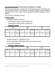
<strong>Fault</strong> <strong>scenario</strong> <strong>simulation</strong> <strong>in</strong> a <strong>feeder</strong>Feeders are l<strong>in</strong>e conductors which connect the stations to the areas tobe fed by those stations. So when there is a fault <strong>in</strong> a <strong>feeder</strong>, there willbe a surge <strong>in</strong> a current. So for the safety aga<strong>in</strong>st such faults, circuitbreakers are used. These conditions can be viewed <strong>in</strong> the work stationwith the help of DCS. Let us see <strong>feeder</strong>s and circuit breakers <strong>in</strong> detail :Transmission and distribution of electrical powerBy transmission and distribution of electrical power is meant itsconveyance from the central station where it is generated to the placeswhere it is demanded by the consumers (like pump<strong>in</strong>g stations,residential and commercial build<strong>in</strong>gs, mills, factories etc.)· The maximum generated voltage <strong>in</strong> advanced countries is 33kVwhile that <strong>in</strong> India is 11kV.· The amount of power that has to be transmitted throughtransmission l<strong>in</strong>es is very large and of this power is transmitted at11kV (or 33kV) the l<strong>in</strong>e current and power loss would be verylarge. Therefore this voltage is stepped up to a higher value byus<strong>in</strong>g step up transformers located <strong>in</strong> sub-stations.· The transmission voltages <strong>in</strong> India are 400 kV, 220 kV and 132kV.· The transmission l<strong>in</strong>es and <strong>feeder</strong>s are 3-phase 3-wire circuits.· The distributors are 3-phase 4-wire circuits because a neutral wireis necessary to supply the s<strong>in</strong>gle-phase loads of domestic andcommercial consumers.· The transmission network is commonly known as Grid.Electric supply system:An electric supply system comprises of the follow<strong>in</strong>g three pr<strong>in</strong>ciplecomponents:a) Power station.b) Transmission l<strong>in</strong>es.c) Distribution l<strong>in</strong>es.
The electrical system is broadly classified as follows:1) D.C. or A.C. system.2) Overhead or underground system.The overhead system is less expensive than the underground one. Inour country this system is mostly adopted for transmission anddistribution of power.Fig (a)The above fig shows a typical layout of power system betweengeneration and use of electric power.
Comparison between D.C. and A.C. systems oftransmission and distributionD.C. system:Few advantages: The transmission of electric power by high voltageD.C. systems has follow<strong>in</strong>g advantages over high voltage A.C. system:· DC systems are economical for long distance bulk powertransmission by overhead l<strong>in</strong>es.· Simple l<strong>in</strong>e construction.· Greater power per conductor.· Ground return is possible.· In DC system, only IR drop is present and IX drop is nil. Thereforevoltage regulation problem is much less serious.· The power flow through a DC l<strong>in</strong>k is easily reversible andcontrolled.· In DC transmission, there is no <strong>in</strong>ductance, capacitance, phasedisplacement and surge problem.· A DC l<strong>in</strong>e has less corona loss.· A DC l<strong>in</strong>e has reduced <strong>in</strong>terference with communication circuits.· There is no sk<strong>in</strong> effect <strong>in</strong> DC, X-section of l<strong>in</strong>e conductor istherefore fully utilized.· Because of less potential stress and negligible dielectric loss,underground cable can be used.· No stability problems.· No synchroniz<strong>in</strong>g difficulties.· In a DC system, potential stress on the <strong>in</strong>sulation is 1/√2 timesthat <strong>in</strong> AC system for same work<strong>in</strong>g voltage, therefore less<strong>in</strong>sulation is required <strong>in</strong> DC system.DisadvantagesThe high voltage DC systems have the follow<strong>in</strong>g disadvantages:· DC system uses complicated converters and DC switch gear isexpensive. Thus <strong>in</strong>stallation is costly.
· Electric power cannot be generated at high DC voltage due tocommutator problems.· In DC system harmonics are generated which require filters.· Converters require considerable reactive power.· Converters do not have overload capability.AC SYSTEMNowadays electrical energy is almost exclusively generated,transmitted and distributed <strong>in</strong> the form of A.C. Let us see its advantagesand disadvantages.Advantages:-(1) In A.C. system, the electric power can be generated at highvoltage.(2) Ma<strong>in</strong>tenance of substations is easy and comparatively at a lowercost.(3) Stepp<strong>in</strong>g-up and stepp<strong>in</strong>g down of an A.C voltage can be doneeasily and efficiently with the help of transformers.Disadvantages:-Note:-(1) There is a need to synchronize the alternators before they are put<strong>in</strong> parallel.(2) Transmission l<strong>in</strong>e construction is comparatively difficult and theamount of copper required is comparatively more.(3) In order to avoid corona loss and also to provide adequateamount of <strong>in</strong>sulation <strong>in</strong> case of overhead l<strong>in</strong>es, more spac<strong>in</strong>gbetween the conductors is required.(4) As a result of sk<strong>in</strong> effect, the resistance of the l<strong>in</strong>e is <strong>in</strong>creased.(5) A.C l<strong>in</strong>e has capacitance, because of which there is a cont<strong>in</strong>uesloss of power due to charg<strong>in</strong>g current even when the l<strong>in</strong>e is open.(a) The best method is to use A.C system for generation anddistribution purpose and DC system for transmission purpose.
(b) By us<strong>in</strong>g mercury are rectifiers and thyratrons, it is possible totransmit electric power by DC system, which can convert AC <strong>in</strong>toDC and vice-versa directly at a reasonable cost. These devicescan handle 30 Megawatt at 400V.L<strong>in</strong>e diagram of typical H.V.D.C transmission l<strong>in</strong>esThe above figure shows a s<strong>in</strong>gle l<strong>in</strong>e diagram of high voltage DC(H.V.D.C) transmission. The generat<strong>in</strong>g station generates electric powerwhich is AC. This voltage is stepped to high voltage by the use of stepuptransformers. This A.C power at high voltage is fed to the mercuryare rectifiers which converts AC <strong>in</strong>to DC. This high DC voltage istransmitted. At receiv<strong>in</strong>g end the DC power converted to AC power us<strong>in</strong>gthyratrons. This AC voltage is then stepped down to low voltage fordistribution by us<strong>in</strong>g a step-down transformer.Choice of Transmission VoltageWhenever transmission l<strong>in</strong>es are concerned there is a specific limit forthe voltage to be used, beyond which there is no economical profit. Thelimit is reached when the cost of conductor, transformer, <strong>in</strong>sulator,supports, switchgear, lightn<strong>in</strong>g arrester and the erection cost is“m<strong>in</strong>imum”.
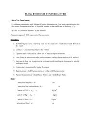
Fig (c)(i)Accord<strong>in</strong>g to modern American practice (based on empiricalformula) empirical l<strong>in</strong>e–to-l<strong>in</strong>e voltage (kV) isV=5.5√(0.62+ )Where,l=Distance of transmission <strong>in</strong> km,P=Estimated maximum KW/phase to be delivered over a s<strong>in</strong>gle circuit.(ii)Voltage <strong>in</strong> kV(l<strong>in</strong>e-to-l<strong>in</strong>e),V=5.5√(0.62+ )Where,l=Distance of transmission <strong>in</strong> km and kVA= Total power.
Underground cables and overhead l<strong>in</strong>esOverhead l<strong>in</strong>es and underground cables are the 2 ways for transmissionor distribution of electric power. Most of the time overhead l<strong>in</strong>es areused; underground cables are rarely used for the follow<strong>in</strong>g reason:(i)(ii)Power is generally transmitted over long distances to loadcentres.Installation costs are very high. Therefore, transmission ofpower over long distances is carried out by us<strong>in</strong>g overheadl<strong>in</strong>es.Important components of overhead l<strong>in</strong>es:(1) Conductors:-Conductors carry power from send<strong>in</strong>g end station to receiv<strong>in</strong>g endstation.(2) Supports:-These are the structures which keep the conductors at a suitablelevel above the ground; they can be poles or towers, depend<strong>in</strong>gupon the work<strong>in</strong>g voltage and the place where they are used.(3) Cross-arms: - Cross arms provide the necessary support to the<strong>in</strong>sulators.(4) Insulators: - They provide <strong>in</strong>sulation to high voltage wire with themetal structure and also provide support to the conductor. Theyalso provide support to bus-bar conductors and other love highvoltage equipment term<strong>in</strong>als.(5) Other miscellaneous items:(1) Lightn<strong>in</strong>g arresters.(2) Fuse(3) Isolat<strong>in</strong>g switches(4) Guard wire(5) Phase plates(6) Vee guards(7) Anticlimb<strong>in</strong>g wires etc.
ConductorsThe follow<strong>in</strong>g are the characteristics that conductor used fortransmission and distribution should possess:(a) In order to withstand mechanical stress, it should have hightensile strength.(b) Low resistivity, so that it has high electrical conductivity.(c) In order to have small weight per unit volume it should have lowspecific gravity.(d) Low cost.All these characteristics are not found <strong>in</strong> a s<strong>in</strong>gle material. So, whileselect<strong>in</strong>g a conductor material for a particular case, a compromise ismade between cost and electrical and mechanical properties.Material used for transmission l<strong>in</strong>esThe most important lead<strong>in</strong>g material used for transmission l<strong>in</strong>es iscopper because it has tensile strength and high conductivity. Alum<strong>in</strong>iumis also used to large extent especially with a steel core for high voltagel<strong>in</strong>e. The selection of materials depends upon the follow<strong>in</strong>g criteria:(i)(ii)(iii)Required mechanical strength and electrical properties.Cost of materials.Local conditions.List of other materials used for transmission l<strong>in</strong>es are:(a) Galvanised steel materials.(b) Galvanised iron.(c) Steel core copper.(d) Cadmium copper materials etc.(e) Phosphor bronze materials etc.Let us see few of them <strong>in</strong> brief.(1) Copper :-· Copper that has not been annealed after be<strong>in</strong>g drawn (Harddrawn copper) conductor is one of the best conductors dueto its high electrical conductivity and high tensile strength forall types of transmission. Hard draw<strong>in</strong>g reduces electrical
conductivity by a small amount but it <strong>in</strong>creases the tensilestrength considerably.· It is a homogeneous material, durability is high and has highscrap value.· It has a high current density so lesser X-sectional area ofconductor is required.Copper conductor hav<strong>in</strong>g steel core are employed for long spantransmission l<strong>in</strong>es, where a comb<strong>in</strong>ation of high conductivity,small sag and m<strong>in</strong>imum cross-section are desired.(2) Alum<strong>in</strong>ium :-(i) Lighter <strong>in</strong> weight as compared to copper, but has smallerconductivity and tensile strength.(ii) Alum<strong>in</strong>ium has 1.6 items the resistivity of copper. So for thesame loss and length of conductor an alum<strong>in</strong>ium conductorshould have 60% greater x-sectional area than that of copperconductor. This <strong>in</strong>creased X-section of alum<strong>in</strong>ium exposes agreater surface to w<strong>in</strong>d pressure. So the support<strong>in</strong>g towersmust be designed for greater transvers strength. Asconsequences of greater sag, the use of higher towers isoften required.(iii) The sag <strong>in</strong> alum<strong>in</strong>ium conductors is greater than the copperconductors.(iv) They are particularly suitable for operation <strong>in</strong> very highambient temperature.(3) Steel cored alum<strong>in</strong>ium (A.C.S.R)Alum<strong>in</strong>ium has low tensile strength, as a result produce greatersag which prohibits their use for longer spans and makes themunsuitable for long distance transmissions. So <strong>in</strong> order to <strong>in</strong>creasethe tensile strength of the alum<strong>in</strong>ium conductor, it is used with acore of galvanized steel wires. The comb<strong>in</strong>ational conductor thusobta<strong>in</strong>ed is called as A.C.S.R. (Alum<strong>in</strong>ium Conductor SteelRe<strong>in</strong>forced).
Fig (d)A.S.C.R conductorThe above figure shows, one steel cored conductor wiresurrounded by 18 wires of alum<strong>in</strong>ium. The alum<strong>in</strong>ium carries bulkof current while the steel core takes a greater percentage ofmechanical stress.· Produces small lag and therefore can be used for longerspans.· A.C.S.R. Conductor gets deteriorated <strong>in</strong> service due toatmospheric corrosion.(4) Galvanised steel· Used for extremely long spans. Because of poor conductivityand high resistance of steel, they are not suitable fortransmitt<strong>in</strong>g large power over a long distance.· Steel wire or iron wire is most advantageous for transmissionof small power over a short distance.
(5) Cadmium copperSometimes copper alloyed with cadmium is used. When 1 or 2percentage of cadmium is added to copper it <strong>in</strong>creases the tensilestrength by about 40 percentages but reduces the conductivityonly by 17 percentages. Cadmium copper is expensive thancopper.· Economical for a l<strong>in</strong>e with long spans and small crosssection.L<strong>in</strong>e support:-The follow<strong>in</strong>g are the characteristics of l<strong>in</strong>e supports used fortransmission and distribution of electric power.· Light <strong>in</strong> weight and less expensive.· It should have high mechanical strength.· Low ma<strong>in</strong>tenance cost and longer life.These l<strong>in</strong>es support can be wooden poles, steel poles, RCC poles andsteel towers.(1) Wooden poles:· Cheap, easily available has <strong>in</strong>sulat<strong>in</strong>g properties and aremost widely used for distribution purpose <strong>in</strong> rural areas.· Used for short spans, up to 60 metres.· The portion of the poles, which is below the ground level, isimpregnated with preservative compounds like creosite oil.· In order to obta<strong>in</strong> high transverse strength, double polestructures like ‘A’ or ‘H’ type (fig e) are used.· Short life, up to 25 to 30 years.
Fig (e)(2) Steel poles· Has great mechanical strength and thus can be used forlonger spans (50-80 metres), but they are costly.· Majority of 3 types:(i) Rail poles(ii) Rolled steel jo<strong>in</strong>ts(iii) Tabular poles· Average life more than 40 years.(3) R.C.C. poles· R.C.C poles possess greater mechanical strength and canbe used for longer span than steel poles(80-200 metres)· Good <strong>in</strong>sulat<strong>in</strong>g properties and low ma<strong>in</strong>tenance.· They have a very long life.
Fig (f)R.C.C poles(4) Steel towers· Wooden poles, steel poles, R.C.C. poles are used fordistribution purpose at low voltage (say 11kV), but steeltowers are <strong>in</strong>variably employed for long distancetransmission at higher voltage.· Troubles regard<strong>in</strong>g lightn<strong>in</strong>g are m<strong>in</strong>imised as each toweracts as a lightn<strong>in</strong>g conductor.· Steel tower has greater mechanical strength.· Longer life span.· Steel towers can withstand most severe climate conditions.· Steel towers are suitable for longer spans.
S<strong>in</strong>gle circuit towerDouble circuit towerFig (g)OVERHEAD LINE INSULATORSInsulators are used <strong>in</strong> order to provide safety and necessary clearancebetween live transmission conductors, which are completely bare and donot have any <strong>in</strong>sulated coat<strong>in</strong>g over it.Required characteristics of an <strong>in</strong>sulator:-(i)(ii)(iii)It should have <strong>in</strong>sulation resistance to avoid current leakage toearth.It should have very high mechanical strength.It should have high dielectric strength to provide high relativepermittivity. Also, it should have high ratio of rapture strength toflash over voltage.
Materials used for <strong>in</strong>sulation(a) Porcela<strong>in</strong>(b) Steatite(c) Glass(d) Synthetic res<strong>in</strong>(1) Porcela<strong>in</strong>· Most commonly used material for <strong>in</strong>sulator <strong>in</strong> overhead l<strong>in</strong>es.· Porcela<strong>in</strong> is usually weak <strong>in</strong> tension and does not withstandtensile strength more than 50MN/m 2· A good porcela<strong>in</strong> <strong>in</strong>sulator has compressive strength ofabout 7000N/m 2 and dielectric strength of 60kV/cm of itsthickness.· Porcela<strong>in</strong> is mechanically stronger than glass.(2) Glass· Ma<strong>in</strong>ly used for E.H.V, AC and DC systems.· Glass <strong>in</strong>sulator is cheaper than porcela<strong>in</strong> when simpleshapes are considered.· Under ord<strong>in</strong>ary atmospheric conditions the glass <strong>in</strong>sulatorcan be used up to 25kV and <strong>in</strong> dry atmosphere, it can beused up to 50kV.· In H.V l<strong>in</strong>es hav<strong>in</strong>g voltage above 100kV, toughened glass isemployed for <strong>in</strong>sulation.(3) Steatite· It is produced by mix<strong>in</strong>g hydrated magnesium silicate withsmall portion of clay and felspar.· It has high <strong>in</strong>sulation resistance.· Steatite has much greater tensile and bend<strong>in</strong>g stress thanporcela<strong>in</strong>. Thus can be used at tension towers or when thetransmission l<strong>in</strong>es take a sharp turn.
Suspension type <strong>in</strong>sulatorFig (i)Fig (j)
(c) Stra<strong>in</strong> <strong>in</strong>sulatorsStra<strong>in</strong> <strong>in</strong>sulators can be of p<strong>in</strong> type <strong>in</strong>sulator or suspension type<strong>in</strong>sulator. Stra<strong>in</strong> <strong>in</strong>sulators are made use when mak<strong>in</strong>g very longspans or corners of transmission l<strong>in</strong>es.Fig (k)(d) Shackle <strong>in</strong>sulatorsShackle <strong>in</strong>sulators can be fixed to a pole directly with a bolt or tothe cross arm. The l<strong>in</strong>e conductor is fixed <strong>in</strong> the groove with a softb<strong>in</strong>d<strong>in</strong>g wire. Before, shackle <strong>in</strong>sulators were used as stra<strong>in</strong><strong>in</strong>sulator, but these days they are used for low voltage distributionl<strong>in</strong>es.
Shackle <strong>in</strong>sulatorFig (l)The reason for failure of <strong>in</strong>sulators(1) Mechanical stress(2) Short circuits(3) Flash-over(4) Crack<strong>in</strong>g of <strong>in</strong>sulator, dust deposition, porosity of material etc.Sag <strong>in</strong> overhead l<strong>in</strong>es:In transmission l<strong>in</strong>es, the conductors are supported at the towersor poles. When the conductor supported <strong>in</strong> this manner it will sagor dip under its own weight and it takes the shape of catenary.The distance between the adjacent support<strong>in</strong>g towers is called the“span”. The difference <strong>in</strong> level between the po<strong>in</strong>ts of supports andthe lowest po<strong>in</strong>ts is known as sag.The factors affect<strong>in</strong>g the sag <strong>in</strong> overhead l<strong>in</strong>es are:(i) Weight of the conductor: The weight of the conductor directlyaffects the sag. Heavier the conductor, greater will be thesag.(ii) Span length: Sag is directly proportional to the square of thespan length, provided other conditions rema<strong>in</strong> unchanged.(iii) If other conditions are rema<strong>in</strong><strong>in</strong>g the same, then the sag is<strong>in</strong>versely proportional to the work<strong>in</strong>g tensile strength.(iv) Sag <strong>in</strong>creases with the <strong>in</strong>crease <strong>in</strong> temperature.
Note: - Few important terms:(a) Sk<strong>in</strong> effect:When direct currents are concerned, the direct current distributesthemselves uniformly over the cross-section of the conductor andtherefore use the centre of the conductor as effectively as they usethe periphery. When alternat<strong>in</strong>g current is concerned, ac ow<strong>in</strong>g to<strong>in</strong>ductance effects with<strong>in</strong> the conductor, crowd toward the outside ofthe conductor. This behaviour is termed as ‘sk<strong>in</strong> effect’. Sk<strong>in</strong> effectraises the apparent resistance of the conduct<strong>in</strong>g material, only thetotal resistance of conductor is changed depend<strong>in</strong>g upon thefrequency of the current and also the diameter of the conductor. Thetotal resistance of the conductor <strong>in</strong>creases, as the frequency of thecurrent <strong>in</strong>creases, and also <strong>in</strong>creases with the <strong>in</strong>crease <strong>in</strong> thediameter of the conductor. The current carried by the centre portion ofthe conductors is reduced by sk<strong>in</strong> effect, thus hollow conductors aresometimes employed to use them more effectively. More often<strong>in</strong>stead of hollow conductor, Alum<strong>in</strong>ium cable steel re<strong>in</strong>forced (ACSR)is used.The sk<strong>in</strong> effect is negligible when the supply frequency is low (
Classification of transmission l<strong>in</strong>esThe transmission l<strong>in</strong>es can be generally classified as follows;(a) Short transmission l<strong>in</strong>es.(b) Medium transmission l<strong>in</strong>es.(c) Long transmission l<strong>in</strong>e.Short transmission l<strong>in</strong>es· Length less than 50km· Operat<strong>in</strong>g voltage less than 20kV.Medium transmission l<strong>in</strong>es· Length between 50km and 160km.· Operat<strong>in</strong>g voltage is between 21kV and 100kV.Long transmission l<strong>in</strong>es· Length more than 160km.· Operat<strong>in</strong>g voltage is above 100kV.Circuit breakersA circuit breaker is an automatically operated electrical switch designedfor to protect an electrical circuit from damage caused by overload orshort circuit. Or, <strong>in</strong> other words, the function of a circuit breaker is toisolate the faulty part of the power system <strong>in</strong> case of abnormalconditions. A protective relay detects abnormal conditions and sends atripp<strong>in</strong>g signal to the circuit breaker. After receiv<strong>in</strong>g the trip commandsignal from the relay the circuit breaker isolates the faulty part of thepower system.
Fig (m)Separation of the contacts of the circuit breakerA circuit breaker has two contacts- a fixed contact and a mov<strong>in</strong>g contact.Under normal conditions these two contacts rema<strong>in</strong> <strong>in</strong> closed position.When the circuit breaker is required to isolate the faulty part, the mov<strong>in</strong>gcontact moves to <strong>in</strong>terrupt the circuit. On the separation of the contacts,the flow of current is <strong>in</strong>terrupted, result<strong>in</strong>g <strong>in</strong> the formation of an arcbetween the contacts. These contacts are placed <strong>in</strong> a closed chamberconta<strong>in</strong><strong>in</strong>g some <strong>in</strong>sulat<strong>in</strong>g medium (like gas or liquid) which ext<strong>in</strong>guishthe arc.Insulat<strong>in</strong>g fluid is used for arc extension and the fluid chosen dependsupon the rat<strong>in</strong>g and type of circuit breaker. The <strong>in</strong>sulat<strong>in</strong>g fluidscommonly used for circuit breaker are:(i) Air at atmospheric pressure(ii) Compressed air(iii) Ultra high vacuum(iv) Oil which produces hydrogen for arc extension(v) Sulphur hexafluoride (SF 6 )Some of the gases which have been used <strong>in</strong> circuit breaker are:· Electromagnetic gases : Sulphur hexafluoride , arcton
· Simple gases: Air, oxygen, hydrogen, nitrogen and carbon dioxide.The important characteristics of the fluids used <strong>in</strong> circuit breaker are:(i)(ii)(iii)(iv)It should have good thermal and chemical stabilityIt should have high declarative strength.Non-<strong>in</strong>flammability and high thermal conductivity.Arc ext<strong>in</strong>guish ability.Classification of circuit breakers(1) High voltage circuit breakers(2) Low voltage circuit breakersHigh voltage circuit breakers :-(a) Oil circuit breakers :-(i) Bulk oil circuit breakers us<strong>in</strong>g a large quantity of oil.(ii) Low oil circuit breakers which operate with a m<strong>in</strong>imumamount of oil.(b) Oil less circuit breakers :-(i) Hard gas circuit breakers(ii) Air blast circuit breakers(iii) Sulphur hexafluoride circuit breaker(iv) Water circuit breakers(v) Vacuum circuit breakersCharacteristics of high voltage rat<strong>in</strong>g circuit breaker :-(i)(ii)High voltage rat<strong>in</strong>g circuit breaker should have high reliabilityelectrically and mechanically.High voltage rat<strong>in</strong>g circuit breaker should be capable of<strong>in</strong>terrupt<strong>in</strong>g capacitive and <strong>in</strong>ductive circuits and fault currentsof all values with<strong>in</strong> their rat<strong>in</strong>g.
Let us see some of the features of major circuit breakers:(1) OIL CIRCUIT BREAKERS (O.C.B)Oil circuit breakers are the most common and oldest type of circuitbreakers. The rat<strong>in</strong>g range of circuit breakers lies <strong>in</strong> range of25MVA at 2.5kV and 5000MVA at 250kV.In oil circuit breaker, the separat<strong>in</strong>g contacts are made to separatewith<strong>in</strong> <strong>in</strong>sulat<strong>in</strong>g oil medium, which has better <strong>in</strong>sulat<strong>in</strong>g propertiesthan air.Few advantages of us<strong>in</strong>g oil as an Arc quench<strong>in</strong>g medium:-(a) Dielectric strength is high(b) As a result of decomposition of oil, it has good cool<strong>in</strong>g property.(c) It acts as an <strong>in</strong>sulator between live part and earth.(d) Surround<strong>in</strong>g oil <strong>in</strong> close proximity to the arc presents a largecool<strong>in</strong>g surface.Few disadvantages:-(a) Highly <strong>in</strong>flammable and can cause an explosion by mix<strong>in</strong>g withair.(b) It requires ma<strong>in</strong>tenance.(c) Periodic replacement.(2) AIR BLAST CIRCUIT BREAKERS:-Air blast circuit breakers is a type of circuit breaker which use ahigh pressure air blast (at a pressure of 20bar) as an arcquench<strong>in</strong>g medium.Range – 132kV and above up to 400kV ,with the brak<strong>in</strong>g capacityup to 7500MVA .But can also be designed to cover the wide rangeof 66kV to 132kV.Few advantages:-(a) No risk of explosion and fire hazards.(b) Consistent and short arc duration
(c) S<strong>in</strong>ce the arc duration is short and consistent, the burn<strong>in</strong>g of thecontact is less due to less arc energy.(d) High speed enclosures facility.(e) Comparatively less ma<strong>in</strong>tenance required.Few disadvantages:-(a) Current chopp<strong>in</strong>g(b) Sensitivity to restrict<strong>in</strong>g voltage(3) SULPHUR HEXAFLUORIDE(SF 6 ) CIRCUIT BREAKER:-Sulphur hexafluoride to other medium such as oil or air for the use<strong>in</strong> circuit breakers for the follow<strong>in</strong>g reasons:(1) Be<strong>in</strong>g an Inert gas, it is non-reactive to the other componentsof circuit breakers.(2) Sulphur hexafluoride has high dielectric strength (about 24times that of air and it is comparable to that of oil)(3) When ext<strong>in</strong>ction of arc is concerned it is about 100 times moreeffective than air.(4) Its heat transfer property is about 16times that of air because ofits high density.Applications:-(1) The circuit breakers are designed for voltages 115kV to 230kV,power rat<strong>in</strong>g of 10MVA to 20MVA and <strong>in</strong>terrupt<strong>in</strong>g times lessthan 3cycles.(2) A typical sulphur hexafluoride circuit breaker consist of<strong>in</strong>terrupter units, each capable of deal<strong>in</strong>g with currents up to60000A and voltage <strong>in</strong> the range of 50 to 80kV.A number ofunits are connected <strong>in</strong> series accord<strong>in</strong>g to the voltage of thesystem.Few Advantages:-(a) No risk of fire.(b) No reduction of dielectric strength.(c) Arc<strong>in</strong>g time is very short; this reduces the erosion of contact.(d) Its operation is very silent.
(e) The current chopp<strong>in</strong>g tendency is m<strong>in</strong>imized by us<strong>in</strong>gsulphur hexafluoride gas at low pressure and low velocity.(f) The breaker is compact <strong>in</strong> size and totally enclosed. Thuselectrical clearances are drastically reduced and areparticularly suitable where explosion hazard exists, like coalm<strong>in</strong>es.Disadvantages:-(a) Expensive(b) Sulphur hexafluoride gas has to be reconditioned after everyoperation of the breaker and additional equipment is requiredfor this purpose.(3) VACUUM CIRCUIT BREAKERS(V.C.B):-Vacuum means the pressure below atmospheric pressurewhich is 760 mm of Hg. In a vacuum circuit breaker, vacuum ofthe order of 10 -5 to 10 -7 (1 torr = 1 mm of Hg) is used as the arcquench<strong>in</strong>g medium. The dielectric strength of the vacuum is1000 times more than that of any other medium.Applications:-(1) Vacuum breakers are be<strong>in</strong>g used for outdoor applicationsrang<strong>in</strong>g from 22kV to 66kV. They are also suitable formajority of applications <strong>in</strong> several areas even with limitedrat<strong>in</strong>g say 60 to 100MVA.(2) Vacuum circuit breakers are used for capacitor-bankswitch<strong>in</strong>g, transformer, react<strong>in</strong>g switch<strong>in</strong>g, where thevoltages are high and current to be <strong>in</strong>terrupted is low.Few important terms regard<strong>in</strong>g circuit breakers:-(1) Arc voltage :-The voltage across the contacts dur<strong>in</strong>g the arc<strong>in</strong>g period isknown as the “arc voltage “.(2) Restrik<strong>in</strong>g voltage:-The transient voltage appear<strong>in</strong>g across the contacts dur<strong>in</strong>garc period is called the “restrik<strong>in</strong>g voltage”.
(3) Recovery voltage:-It is normal frequency (50Hz) r.m.s. voltage that appearsacross the contact of the circuit breaker after the f<strong>in</strong>alext<strong>in</strong>ction. It is approximately equal to the system voltage.(4) Rate of Rise of restrik<strong>in</strong>g voltage(RRRV):-The average RRRV =Peak value of restrik<strong>in</strong>g voltageTime taken to reach the peak value(5) Current Chopp<strong>in</strong>g:-When low <strong>in</strong>ductive current (e.g. current to a shunt reactoror magnetis<strong>in</strong>g current of a transformer) is <strong>in</strong>terrupted by acircuit breaker and the arc quench<strong>in</strong>g force of the circuitbreaker is more than necessary to <strong>in</strong>terrupt a low magnitudeof current, the current will be <strong>in</strong>terrupted before its manualzero <strong>in</strong>stant. It is termed as current chopp<strong>in</strong>g.Rat<strong>in</strong>g of circuit breakers:-A circuit breaker is expected to perform the follow<strong>in</strong>g duties (besidesnormal work<strong>in</strong>g) under short circuit/fault conditions:(a) To open the contacts to clear the fault and isolat<strong>in</strong>g the faultysection.(b) To close the contacts on to a fault.(c) It must be able to carry fault current for a short time while anothercircuit breaker (<strong>in</strong> series) is clear<strong>in</strong>g the fault.Therefore, <strong>in</strong> addition to the rated voltage, current andfrequency, circuit breakers have the follow<strong>in</strong>g important rat<strong>in</strong>gs.(i) Break<strong>in</strong>g capacity(ii) Mak<strong>in</strong>g capacity(iii) Short-time capacity
(i)Break<strong>in</strong>g capacity:-It is the current (r.m.s. value) that a circuit breaker is capable ofbreak<strong>in</strong>g under specified conditions (e.g. PPPV, power factor)and given recovery voltage.(ii)(iii)Break<strong>in</strong>g capacity for a 3-phase circuit breaker = √3 × ×10 -6 MVA ;Where V=Rated service l<strong>in</strong>es <strong>in</strong> volts,I =rated break<strong>in</strong>g current (symmetrical or asymmetrical)<strong>in</strong> ampere.Mak<strong>in</strong>g capacity:-The peak value of current (<strong>in</strong>clud<strong>in</strong>g the DC component) dur<strong>in</strong>gfirst cycle of current wave after the closure of circuit breaker isknown as “mak<strong>in</strong>g capacity”.Mak<strong>in</strong>g capacity = 2.55 × symmetrical break<strong>in</strong>g capacityShort-time capacity:-The short time rat<strong>in</strong>g of a circuit breaker depends upon itsability to withstand the temperature rise and the electromagneticforce effects. The oil circuit breakers have a specified limit of 3seconds when the ratio of symmetrical break<strong>in</strong>g current to therated normal current does not exceed 40. However if this ratioexceeds 40, then the specified limit is 1second.Normal current rat<strong>in</strong>g:-It is the r.m.s value of current which the circuit breaker iscapable of carry<strong>in</strong>g cont<strong>in</strong>uously at its rated frequency underspecified conditions.