SP500 AC Drive Installation and Operation ... - Reliance Electric
SP500 AC Drive Installation and Operation ... - Reliance Electric
SP500 AC Drive Installation and Operation ... - Reliance Electric
- No tags were found...

You also want an ePaper? Increase the reach of your titles
YUMPU automatically turns print PDFs into web optimized ePapers that Google loves.
<strong>SP500</strong> <strong>AC</strong> <strong>Drive</strong><strong>Installation</strong> <strong>and</strong> <strong>Operation</strong> ManualVersion 3.1Instruction Manual D2-3356-5
The information in this manual is subject to change without notice.Throughout this manual, the following notes are used to alert you to safety considerations:!ATTENTION: Identifies information about practices or circumstances that can lead to personalinjury or death, property damage, or economic loss.Important: Identifies information that is critical for successful application <strong>and</strong> underst<strong>and</strong>ing of the product.The thick black bar shown on the outside margin of this page will be used throughout this instruction manual tosignify new or revised text or figures.!ATTENTION: Only qualified electrical personnel familiar with the construction <strong>and</strong> operation ofthis equipment <strong>and</strong> the hazards involved should install, adjust, operate, <strong>and</strong>/or service thisequipment. Read <strong>and</strong> underst<strong>and</strong> this manual in its entirety before proceeding.<strong>Reliance</strong>, ReSource, <strong>and</strong> AutoMax are trademarks of Rockwell Automation.©1999 Rockwell International Corporation
CONTENTSChapter 1Chapter 2Chapter 3Chapter 4Introduction1.1 Who Should Use This Manual ......................................................................... 1-11.2 <strong>Installation</strong> Overview ....................................................................................... 1-11.3 Requesting Assistance from <strong>Reliance</strong> <strong>Electric</strong> ................................................ 1-1Learning About the <strong>SP500</strong> <strong>Drive</strong>2.1 St<strong>and</strong>ard Features........................................................................................... 2-12.2 <strong>Drive</strong> Description ............................................................................................. 2-22.3 Identifying the <strong>Drive</strong> by Model Number ........................................................... 2-62.3.1 Power Ratings <strong>and</strong> NEMA Enclosure Ratings ...................................... 2-72.3.2 Enclosure Ratings <strong>and</strong> Sizes ................................................................ 2-82.4 Component Locations...................................................................................... 2-82.5 Option Kits ..................................................................................................... 2-13<strong>SP500</strong> System Planning3.1 <strong>Installation</strong> Site Requirements......................................................................... 3-13.1.1 Determining the Total Area Required for <strong>Installation</strong> ............................ 3-23.1.2 Providing Proper Air Flow Clearances .................................................. 3-43.1.3 Verifying the <strong>Drive</strong>’s Power Loss Rating ............................................... 3-43.2 Wiring Requirements ....................................................................................... 3-43.2.1 Verifying Conduit Sizes ......................................................................... 3-43.2.2 Recommended Power Wire Sizes......................................................... 3-43.2.3 Recommended Control <strong>and</strong> Signal Wire Sizes ..................................... 3-63.2.4 Recommended Motor Lead Lengths..................................................... 3-63.3 Selecting Input <strong>AC</strong> Line Branch Circuit Fuses................................................. 3-83.4 Installing an Emergency Stop.......................................................................... 3-93.4.1 Complying with Machinery Safety St<strong>and</strong>ard EN 60204-1:1992 ............ 3-93.5 Motor Considerations ...................................................................................... 3-93.5.1 Single-Motor Applications...................................................................... 3-93.5.2 Multiple-Motor Applications ................................................................. 3-10Installing the <strong>Drive</strong>4.1 Mounting the <strong>Drive</strong> .......................................................................................... 4-14.2 Routing Wires .................................................................................................. 4-14.3 Installing External Components....................................................................... 4-64.3.1 Disconnects........................................................................................... 4-64.3.2 Input <strong>AC</strong> Line Branch Protection........................................................... 4-64.3.3 Transformers......................................................................................... 4-64.3.4 Output Contactors ................................................................................. 4-74.3.5 Mechanical Motor Overload Protection ................................................. 4-74.4 Setting the Analog Input Jumper on the Regulator Board ............................... 4-74.5 Preparing the Motor......................................................................................... 4-8ContentsI
Chapter 5Chapter 6Chapter 7Chapter 8Chapter 9Wiring the <strong>Drive</strong>5.1 Input Power Wiring...........................................................................................5-15.2 Signal <strong>and</strong> Control Wiring ................................................................................5-35.2.1 Analog Speed Reference Wiring ...........................................................5-35.2.2 Analog Output Wiring.............................................................................5-45.2.3 Digital Input Wiring.................................................................................5-45.2.4 Snubber Resistor Wiring........................................................................5-85.2.5 Output Status Relay Wiring .................................................................5-105.3 Output Power Wiring ......................................................................................5-105.4 Grounding ......................................................................................................5-11Completing the <strong>Installation</strong>6.1 Checking the <strong>Installation</strong> With the Power Off...................................................6-16.2 Checking <strong>Drive</strong> <strong>Operation</strong> ................................................................................6-2Keypad <strong>and</strong> Display <strong>Operation</strong>7.1 Display Description ..........................................................................................7-17.2 Key Descriptions ..............................................................................................7-27.3 LED Descriptions .............................................................................................7-37.4 Program Mode .................................................................................................7-47.5 Monitor Mode ...................................................................................................7-57.5.1 Displaying the Percent Selected Speed Reference...............................7-67.5.2 Scaling the RPM Display <strong>and</strong> Reference Using F-08 ............................7-67.6 <strong>Drive</strong> Control ....................................................................................................7-67.6.1 Changing the Reference Using the Keypad ..........................................7-7Programming Reference8.1 Displaying or Changing Parameter Values ......................................................8-18.2 Ensuring Program Security ..............................................................................8-38.3 Parameter Descriptions....................................................................................8-5Troubleshooting Reference9.1 Verifying DC Bus Voltage.................................................................................9-19.2 Troubleshooting the <strong>Drive</strong> Using Fault Codes .................................................9-39.3 Accessing <strong>and</strong> Clearing the Error Log .............................................................9-59.4 Checking the <strong>Drive</strong>’s Power Module Circuitry with the Power Off....................9-7Appendix A Technical Specifications........................................................................................... A-1Appendix B Record of User Settings ........................................................................................... B-1Appendix C Alphabetical Listing of Parameters........................................................................... C-1Appendix D Compliance with Machinery Safety St<strong>and</strong>ard EN-60204-1:1992 ............................. D-1Appendix E Compliance with Electromagnetic Compatibility St<strong>and</strong>ards ..................................... E-1Appendix F Replacement Parts................................................................................................... F-1GlossaryIndex..................................................................................................................... Glossary-1...........................................................................................................................Index-1II <strong>SP500</strong> <strong>AC</strong> <strong>Drive</strong> <strong>Installation</strong> <strong>and</strong> <strong>Operation</strong> Manual Version 3.1
List of FiguresFigure 2.1 – <strong>SP500</strong> System Diagram ....................................................................... 2-3Figure 2.2 – <strong>SP500</strong> System Diagram (Continued) ................................................... 2-4Figure 2.3 – Regulator Board Component Locations ............................................... 2-5Figure 2.4 – Identifying the <strong>Drive</strong> Model Number ..................................................... 2-6Figure 2.5 – Enclosure A Component Locations ...................................................... 2-9Figure 2.6 – Enclosure B Component Locations .................................................... 2-10Figure 2.7 – Enclosure C Component Locations.................................................... 2-11Figure 2.8 – Enclosure D Component Locations.................................................... 2-12Figure 3.1 – Enclosure A Dimensions ...................................................................... 3-2Figure 3.2 – Enclosure B Dimensions ...................................................................... 3-2Figure 3.3 – Enclosure C Dimensions ...................................................................... 3-3Figure 3.4 – Enclosure D Dimensions ...................................................................... 3-3Figure 3.5 – How to Measure Motor Lead Lengths .................................................. 3-6Figure 4.1 – Enclosure A Wire Routing Locations .................................................... 4-2Figure 4.2 – Enclosure B Wire Routing Locations.................................................... 4-3Figure 4.3 – Enclosure C Wire Routing Locations.................................................... 4-4Figure 4.4 – Enclosure D Wire Routing Locations.................................................... 4-5Figure 4.5 – Jumper J6 Settings for the Analog Input Speed Reference ................. 4-8Figure 5.1 – Typical <strong>Electric</strong>al Connections.............................................................. 5-2Figure 5.2 – Typical Control Terminal Strip Connections ......................................... 5-3Figure 5.3 – Analog Speed Reference Wiring Connections ..................................... 5-4Figure 5.4 – Analog Output Wiring Connections ...................................................... 5-4Figure 5.5 – Two-Wire Start/Stop Sample Control Wiring ........................................ 5-5Figure 5.6 – Three-Wire Start/Stop Sample Control Wiring..................................... 5-5Figure 5.7 – Multi-Speed Preset Sample Control Wiring.......................................... 5-6Figure 5.8 – Terminal Usage During Multi-Speed Preset <strong>Operation</strong> ........................ 5-7Figure 5.9 – Snubber Resistor Wiring Connections for M/N 1SU2xxxx <strong>Drive</strong>s ........ 5-9Figure 5.10 – Snubber Resistor Wiring Connections for M/N 1SU4xxxx <strong>and</strong>1SU5xxxx <strong>Drive</strong>s ................................................................................ 5-9Figure 5.11 – Output Status Relay Wiring Connections ......................................... 5-10Figure 7.1 – <strong>SP500</strong> Keypad <strong>and</strong> Display.................................................................. 7-1Figure 7.2 – <strong>SP500</strong> Menu Structure ......................................................................... 7-4Figure 7.3 – Example of a Program Mode Display.................................................. 7-5Figure 7.4 – Example of a Monitor Mode Display..................................................... 7-6Figure 8.1 – Manual Torque Boost Adjustment Range............................................. 8-7Figure 8.2 – Volts/Hertz Curve ................................................................................. 8-8Figure 9.1 – DC Bus Terminals on Model 1SU1xxxx <strong>and</strong> 1SU2xxxx <strong>Drive</strong>s ............ 9-2Figure 9.2 – DC Bus Terminals on Model 1SU4xxxx <strong>and</strong> 1SU5xxxx <strong>Drive</strong>s (except1SU4x015, 1SU4x020)......................................................................... 9-2Figure 9.3 – DC Bus Terminals on Model 1SU4x015 <strong>and</strong> 1SU4x020 <strong>Drive</strong>s........... 9-2ContentsIII
IV <strong>SP500</strong> <strong>AC</strong> <strong>Drive</strong> <strong>Installation</strong> <strong>and</strong> <strong>Operation</strong> Manual Version 3.1
List of TablesTable 2.1 – <strong>SP500</strong> Model Number Notation ............................................................. 2-6Table 2.2 – Power <strong>and</strong> NEMA Enclosure Ratings .................................................... 2-7Table 2.3 – <strong>SP500</strong> Option Kits ............................................................................... 2-13Table 3.1 – Air Flow Clearances............................................................................... 3-4Table 3.2 – Recommended Power Wire Sizes for M/N 1SU1xxxx <strong>and</strong>1SU2xxxx <strong>Drive</strong>s................................................................................... 3-5Table 3.3 – Recommended Power Wire Sizes for M/N 1SU4xxxx <strong>and</strong>1SU5xxxx <strong>Drive</strong>s................................................................................... 3-5Table 3.4 – Recommended Power Wire Sizes for M/N 1SU4x015 <strong>and</strong>1SU4x020 <strong>Drive</strong>s .................................................................................. 3-5Table 3.5 – Recommended Power Terminal Tightening Torque .............................. 3-5Table 3.6 – Recommended Control <strong>and</strong> Signal Wire Sizes <strong>and</strong> Tightening Torque 3-6Table 3.7 – Motor Lead Lengths............................................................................... 3-7Table 3.8 – Reactors ................................................................................................ 3-7Table 3.9 – <strong>AC</strong> Input Line Fuse Selection Values .................................................... 3-8Table 7.1 – Key Descriptions.................................................................................... 7-2Table 7.2 – <strong>Drive</strong> Status LED Descriptions .............................................................. 7-3Table 7.3 – Monitor Mode LED Descriptions ............................................................ 7-3Table 8.1 – Multi-Speed Presets Digital Inputs....................................................... 8-15Table 8.2 – Auto-Restartable Faults ....................................................................... 8-16Table 9.1 – <strong>Drive</strong> Faults <strong>and</strong> Corrective Actions ...................................................... 9-3Table 9.2 – Resistance Checks for Input Diodes...................................................... 9-8Table 9.3 – Resistance Checks for IGBTs................................................................ 9-8ContentsV
VI <strong>SP500</strong> <strong>AC</strong> <strong>Drive</strong> <strong>Installation</strong> <strong>and</strong> <strong>Operation</strong> Manual Version 3.1
CHAPTER 1IntroductionThis chapter describes the manual’s intended audience <strong>and</strong> provides an overview ofthe <strong>SP500</strong> drive’s installation process.1.1 Who Should Use This ManualThis manual is intended for qualified electrical personnel responsible for installing,programming, starting up, <strong>and</strong> maintaining the <strong>SP500</strong> drive.1.2 <strong>Installation</strong> OverviewThis manual describes how to install <strong>and</strong> troubleshoot the <strong>SP500</strong> drive. <strong>Drive</strong>installation consists of the following basic tasks:• Plan your installation using the guidelines presented in chapter 3. If your installationmust be in compliance with Electromagnetic Compatibility St<strong>and</strong>ards, readAppendix E also.• Mount the drive <strong>and</strong> install external components according to the guidelinespresented in chapter 4.• Wire the drive’s input power, output power, <strong>and</strong> control signal terminal strip using theinstructions in chapter 5.• Adjust parameter values, if required. The parameters are described in chapter 8. Forquick reference, the factory-set values are listed in Appendix B.• Perform the power-off <strong>and</strong> power-on checks described in chapter 6 to complete theinstallation.If problems occur during drive operation, refer to chapter 9. Appendix F lists the partsof the drive that can be replaced.Before you begin the installation procedure, become familiar with the drive by readingchapter 2, which provides an overview of the drive <strong>and</strong> its features, chapter 7, whichdescribes the operation of the keypad <strong>and</strong> the display, <strong>and</strong> Appendix A, which lists thedrive’s technical specifications.1.3 Requesting Assistance from <strong>Reliance</strong> <strong>Electric</strong>If you have any questions or problems with the products described in this instructionmanual, contact your local <strong>Reliance</strong> <strong>Electric</strong> sales office. For technical assistance, call1-800-726-8112, Monday through Friday, 8:00 AM to 5:00 PM (EST).Introduction 1-1
1-2 <strong>SP500</strong> <strong>AC</strong> <strong>Drive</strong> <strong>Installation</strong> <strong>and</strong> <strong>Operation</strong> Manual Version 3.1
CHAPTER 2Learning About the <strong>SP500</strong> <strong>Drive</strong>This chapter describes the <strong>SP500</strong> drive <strong>and</strong> how to identify it based on its modelnumber. This chapter also provides power <strong>and</strong> enclosure rating information.2.1 St<strong>and</strong>ard FeaturesThe <strong>SP500</strong> drive has the following features:• On-board keypad <strong>and</strong> display providing:Start/Stop/Reset controlForward/Reverse (reverse-disable selectable)Setpoint adjustmentMotor RPM, %load, or output voltage display<strong>Drive</strong> diagnostics• 500 millisecond power dip ride-through• 150% overload for one minute (nominal)• 0.5 to 240 Hz three-phase voltage output• NEMA 1 <strong>and</strong> NEMA 4/12 enclosures• A snubber resistor braking signal <strong>and</strong> a scaled voltage analog output(0 to 10 VDC) which is proportional to:Output frequencyOutput ampsOutput voltageSelected reference• Quiet motor operation with high carrier frequency selection• <strong>Drive</strong> protectionOvercurrentShort circuitGround faultOvervoltageUndervoltageOvertemperature• UL/CSA electronic overload that meets NEC/CEC requirementsLearning About the <strong>SP500</strong> <strong>Drive</strong> 2-1
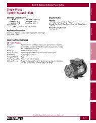
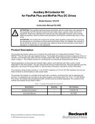
• User-selectable relay contact for indications of drive running, drive faulted, or driveat selected speed• User-selectable power-up start, auto-restart, <strong>and</strong> coast-to-rest or ramp-to-rest stopfunctions• User-selectable local or remote operation• 29 user-adjustable software parameters2.2 <strong>Drive</strong> DescriptionThe <strong>SP500</strong> drive is an <strong>AC</strong> PWM (pulse-width-modulated) inverter that operates onsingle- or three-phase power. See figures 2.1 <strong>and</strong> 2.2. <strong>AC</strong> input power is applied to thedrive’s input terminals. Voltage transients are suppressed by threemetal-oxide-varistor (MOV) suppressors. These suppressors keep any input voltagetransients within the maximum voltage rating of the input diode module.The input diode module rectifies the incoming <strong>AC</strong> voltage into a constant DC busvoltage which is filtered by the DC bus capacitor bank. An internal DC-to-DC powersupply uses power from the DC bus <strong>and</strong> provides the necessary voltages required bythe drive. Under regulator software control, the IGBT (insulated-gatebipolar-transistor) inverter bridge converts the constant DC voltage into an <strong>AC</strong> PWMwaveform. The regulator switches the IGBT inverter bridge using a 4, 6, or 8 kHzcarrier frequency (user-selectable). A low carrier frequency maximizes the powerrating of the drive but also increases acoustic noise. A high carrier frequency selectionreduces acoustic noise but results in a derating of the drive’s efficiency.The volts per hertz (V/Hz) regulator governs the open-loop operation of the drive foradjustable-speed performance of <strong>AC</strong> induction <strong>and</strong> synchronous motors. Theregulator maintains a ratio of voltage to output frequency that provides constant orvariable torque across a wide speed range. <strong>Drive</strong> operation can be adjusted by theparameters entered through the keypad. A microprocessor on the Regulator boardcontrols drive regulation. See figure 2.3. The Regulator board accepts internal powerfeedback signals <strong>and</strong> an external speed reference signal. The Regulator boardprovides display data for a four-character display, which is used to indicate driveparameters, parameter values, <strong>and</strong> fault codes.The drive can be controlled either locally through the keyboard <strong>and</strong> display (seesection 7) or remotely through the terminal strip (see section 5).The drive is intended to operate trip-free under any condition. The drive uses selectedsignals to extend the acceleration (starting) <strong>and</strong> deceleration (stopping) rates of themotor when an overcurrent condition occurs. When a fault does occur, however, theregulator generates an instantaneous electronic trip (IET) signal to turn the drive off(coast-to-rest). The drive stores an indication or record of the IET fault, which can beviewed on the four-character display. After a fault, the STOP/RESET key or auser-supplied IET RESET pushbutton must be pressed to reset the IET signal <strong>and</strong>clear the fault from the drive.2-2 <strong>SP500</strong> <strong>AC</strong> <strong>Drive</strong> <strong>Installation</strong> <strong>and</strong> <strong>Operation</strong> Manual Version 3.1
.Figure 2.1 – <strong>SP500</strong> System DiagramLearning About the <strong>SP500</strong> <strong>Drive</strong> 2-3
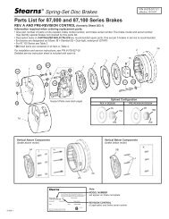
Figure 2.2 – <strong>SP500</strong> System Diagram (Continued)2-4 <strong>SP500</strong> <strong>AC</strong> <strong>Drive</strong> <strong>Installation</strong> <strong>and</strong> <strong>Operation</strong> Manual Version 3.1
Figure 2.3 – Regulator Board Component LocationsLearning About the <strong>SP500</strong> <strong>Drive</strong> 2-5
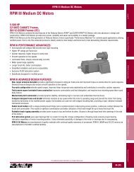
2.3 Identifying the <strong>Drive</strong> by Model NumberA model number identifies each <strong>SP500</strong> <strong>AC</strong> drive. See figure 2.4. This number appearson the shipping label <strong>and</strong> on the drive’s nameplate located on the right side of thedrive housing. The drive’s model number contains codes that indicate: input voltagerange, enclosure rating, <strong>and</strong> horsepower rating. See section 2.3.1 for moreinformation on the drive power ratings. See section 2.3.2 for more information on thedrive enclosure ratings.Figure 2.4 – Identifying the <strong>Drive</strong> Model NumberAll <strong>SP500</strong> drives described in this instruction manual function in the same manner. Toidentify the mechanical differences between certain models, the manual uses thenotation in table 2.1.Table 2.1 – <strong>SP500</strong> Model Number NotationModel Notation Input Voltage Horsepower1SU1xxxx 115 V<strong>AC</strong> ¼ - 1 HP1SU2xxxx 208 - 230 V<strong>AC</strong> 1, 2, 3, 5, 7.5, 10 HP1SU4xxxx 380 - 460 V<strong>AC</strong> 1, 2, 3, 5, 7.5, 10, 15, 20 HP1SU5xxxx 575 V<strong>AC</strong> 1, 2, 3, 5, 7.5, 10 HP2-6 <strong>SP500</strong> <strong>AC</strong> <strong>Drive</strong> <strong>Installation</strong> <strong>and</strong> <strong>Operation</strong> Manual Version 3.1
2.3.1 Power Ratings <strong>and</strong> NEMA Enclosure RatingsTable 2.2 provides <strong>SP500</strong> drive power <strong>and</strong> NEMA enclosure ratings.Input Power<strong>and</strong> HorsepowerRating*Table 2.2 – Power <strong>and</strong> NEMA Enclosure RatingsPowerLossWatts***ModelNEMA Enclosure <strong>AC</strong> Input Input Input OutputNumberRating Size** Volts Amps KVA Amps*1SU11001 Single-Phase - 1 HP 1 A 115 13.1 1.5 6.8 801SU14001 Single-Phase - Demo ---- ---- 115 5.2 0.6 2.0 801SU21001 Single-Phase - 1 HP 1 A 200-230 5.0 1.3 1.7 701SU24001 Single-Phase - 1 HP 4X/12 A 200-230 5.0 1.3 1.7 701SU21002 Single-Phase - 2 HP4 kHz Carrier6 kHz Carrier8 kHz Carrier1 A200-230200-230200-23019.117.215.34.44.03.57.57.06.51201201201SU21001 Three-Phase - 1 HP 1 A 200-230 7.0 2.8 5.0 701SU24001 Three-Phase - 1 HP4 kHz Carrier6 kHz Carrier8 kHz Carrier4X/12 A200-230200-230200-2306.45.25.22.62.02.04.53.63.67070701SU21002Three-Phase - 2 HP4 kHz Carrier6 kHz Carrier8 kHz Carrier1 A200-230200-230200-2301SU24002 Three-Phase - 2 HP 4X/12 C 200-230 9.9 4.0 7.5 1201SU21003 Three-Phase - 3 HP 1 C 200-230 12.5 5.0 10.6 2101SU24003 Three-Phase - 3 HP 4X/12 C 200-230 12.5 5.0 10.6 2101SU21005 Three-Phase - 5 HP 1 C 200-230 17.2 6.9 14.2 2501SU24005 Three-Phase - 5 HP 4X/12 C 200-230 17.2 6.9 14.2 2501SU41001 Three-Phase - 1 HP 1 B 380-460 2.5 2.0 2.1 601SU44001 Three-Phase - 1 HP 4X/12 B 380-460 2.5 2.0 2.1 601SU41002 Three-Phase - 2 HP 1 B 380-460 4.2 3.3 3.4 1001SU44002 Three-Phase - 2 HP 4X/12 B 380-460 4.2 3.3 3.4 1001SU41003 Three-Phase - 3 HP 1 B 380-460 6.4 5.1 5.3 1401SU44003 Three-Phase - 3 HP 4X/12 B 380-460 6.4 5.1 5.3 1401SU41005 Three-Phase - 5 HP 1 B 380-460 9.9 8.0 8.2 1801SU44005 Three-Phase - 5 HP 4X/12 B 380-460 9.9 8.0 8.2 1801SU41007 Three-Phase - 7.5 HP 1 C 380-460 13.4 10.7 11.1 2101SU44007 Three-Phase - 7.5 HP 4X/12 C 380-460 13.4 10.7 11.1 2101SU41010 Three-Phase - 10 HP 1 C 380-460 17.2 13.7 14.2 2501SU44010 Three-Phase - 10 HP 4X/12 C 380-460 17.2 13.7 14.2 2501SU41015 Three-Phase - 15 HP 1 D 380-460 25.4 20.2 21.0 3751SU42015 Three-Phase - 15 HP 12 D 380-460 25.4 20.2 21.0 3751SU41020 Three-Phase - 20 HP 1 D 380-460 32.7 26.1 27.0 6001SU42020 Three-Phase - 20 HP 12 D 380-460 32.7 26.1 27.0 6001SU51001 Three-Phase - 1 HP 1 B 575 2.0 2.0 1.6 501SU54001 Three-Phase - 1 HP 4X/12 B 575 2.0 2.0 1.6 509.99.38.74.03.83.57.57.06.5707070Learning About the <strong>SP500</strong> <strong>Drive</strong> 2-7
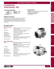
Input Power<strong>and</strong> HorsepowerRating*Table 2.2 - Power <strong>and</strong> NEMA Enclosure Ratings (Continued)PowerLossWatts***ModelNumberNEMARatingEnclosureSize**<strong>AC</strong> InputVoltsInputAmpsInputKVAOutputAmps*1SU51002 Three-Phase - 2 HP 1 B 575 3.4 3.3 2.7 901SU54002 Three-Phase - 2 HP 4X/12 B 575 3.4 3.3 2.7 901SU51003 Three-Phase - 3 HP 1 B 575 5.2 5.1 4.3 1201SU54003 Three-Phase - 3 HP 4X/12 B 575 5.2 5.1 4.3 1201SU51005 Three-Phase - 5 HP 1 B 575 7.5 7.5 6.2 1501SU54005 Three-Phase - 5 HP 4X/12 B 575 7.5 7.5 6.2 1501SU51007 Three-Phase - 7.5 HP 1 C 575 10.9 10.9 9.0 1801SU54007 Three-Phase - 7.5 HP 4X/12 C 575 10.9 10.9 9.0 1801SU51010 Three-Phase - 10 HP 1 C 575 14.5 14.4 12.0 2501SU54010 Three-Phase - 10 HP 4X/12 C 575 14.5 14.4 12.0 250* To properly size the drive for motor nameplate horsepower <strong>and</strong> amps, refer to section 3.5 for more information. Derating for 4, 6, 8kHzcarrier frequencies is not required except for the units indicated.** Refer to section 2.3.2 for more information on enclosure sizes.*** Full-load at all carrier frequencies. Refer to section 3.1.3 for more information.2.3.2 Enclosure Ratings <strong>and</strong> SizesEach of the <strong>SP500</strong> drives have one of the following NEMA ratings:NEMARating Description1 Vented. For general-purpose indoor applications.4X/12 Not vented. Supplied with base <strong>and</strong> keypad gaskets. For use in indoorenvironments that require a water-tight <strong>and</strong> dust-tight enclosure. Anenclosure with this NEMA rating encompasses both ratings (4X <strong>and</strong> 12).12 Intended for use in indoor environments that require a dust-tight <strong>and</strong>drip-tight enclosure.See table 2.2 for a listing of drive model numbers <strong>and</strong> their individual NEMA ratings.For clarity in this manual, <strong>SP500</strong> drive enclosures are identified by size as enclosuresA through D. Refer to table 2.2 for a listing of the drive model numbers <strong>and</strong> theirindividual enclosure sizes. Refer to section 3.1.1 for the dimensions of enclosures Athrough D.2.4 Component LocationsFigures 2.5 through 2.8 show the main components of the <strong>SP500</strong> drives (enclosures Athrough D). Appendix F lists replacement parts.2-8 <strong>SP500</strong> <strong>AC</strong> <strong>Drive</strong> <strong>Installation</strong> <strong>and</strong> <strong>Operation</strong> Manual Version 3.1
CONTROL STRIPTERMINALREGULATOR PCBMEMBRANE SWITCH/BR<strong>AC</strong>KET ASSEMBLYINTERNAL FANASSEMBLYPOWER TERMINAL STRIPPOWER PCBGND CONNECTIONFigure 2.5 – Enclosure A Component LocationsLearning About the <strong>SP500</strong> <strong>Drive</strong> 2-9
CONTROL TERMINAL STRIPREGULATOR PCBMEMBRANE SWITCH/BR<strong>AC</strong>KET ASSEMBLYINTERNAL FANASSEMBLYCAP<strong>AC</strong>ITOR PCB(3 & 5 HP ONLY)POWER PCBGND CONNECTIONPOWER TERMINAL STRIPFigure 2.6 – Enclosure B Component Locations2-10 <strong>SP500</strong> <strong>AC</strong> <strong>Drive</strong> <strong>Installation</strong> <strong>and</strong> <strong>Operation</strong> Manual Version 3.1
CONTROL CONTROL TERMINAL TERMINAL STRIPSTRIPREGULATOR PCBMEMBRANE SWITCH/BR<strong>AC</strong>KET ASSEMBLYINTERNAL FANASSEMBLYCAP<strong>AC</strong>ITOR CAP<strong>AC</strong>ITOR PCB PCBPOWER POWER TERMINAL TERMINALSTRIPGND CONNECTIONSSTRIPGND CONNECTIONSPOWER PCB PCBFigure 2.7 – Enclosure C Component LocationsLearning About the <strong>SP500</strong> <strong>Drive</strong> 2-11
Figure 2.8 – Enclosure D Component Locations2-12 <strong>SP500</strong> <strong>AC</strong> <strong>Drive</strong> <strong>Installation</strong> <strong>and</strong> <strong>Operation</strong> Manual Version 3.1
2.5 Option KitsTable 2.3 provides a listing of the available <strong>SP500</strong> option kits.Table 2.3 – <strong>SP500</strong> Option KitsOption Kit DescriptionLow Energy Snubber Resistor Braking Kit forM/N 1SU2xxxx <strong>Drive</strong>sLow Energy Snubber Resistor Braking Kit forM/N 1SU4xxxx <strong>Drive</strong>s*Low Energy Snubber Resistor Braking Kit forM/N 1SU4x015 <strong>and</strong> 1SU4x020 <strong>Drive</strong>sLow Energy Snubber Resistor Braking Kit forM/N 1SU5xxxx <strong>Drive</strong>s*Option Kit InstructionModel Number Manual2DB2005 D2-31782DB4010 D2-31792SR40700 D2-32912SR418002DB5010 D2-3180*Snubber resistor braking kits for M/N 1SU4xxxx <strong>and</strong> 1SU5xxxx drives require connection to the snubberresistor braking 10V power supply. See section 5.2.4 for more information.Learning About the <strong>SP500</strong> <strong>Drive</strong> 2-13
2-14 <strong>SP500</strong> <strong>AC</strong> <strong>Drive</strong> <strong>Installation</strong> <strong>and</strong> <strong>Operation</strong> Manual Version 3.1
CHAPTER 3<strong>SP500</strong> System PlanningThis chapter provides information that you must consider when planning an <strong>SP500</strong>drive installation. <strong>Installation</strong> site, wiring, <strong>and</strong> motor application requirements areincluded.!ATTENTION: Only qualified electrical personnel familiar with theconstruction <strong>and</strong> operation of this equipment <strong>and</strong> the hazards involvedshould install, adjust, operate, or service this equipment. Read <strong>and</strong>underst<strong>and</strong> this manual <strong>and</strong> other applicable manuals in their entiretybefore proceeding.ATTENTION: Use of power correction capacitors on the output of thedrive can result in erratic operation of the motor, nuisance tripping,<strong>and</strong>/or permanent damage to the drive. Remove power correctioncapacitors before proceeding.ATTENTION: The user is responsible for conforming with all applicablelocal, national, <strong>and</strong> international codes.3.1 <strong>Installation</strong> Site RequirementsIt is important to properly plan before installing an <strong>SP500</strong> drive to ensure that thedrive’s environment <strong>and</strong> operating conditions are satisfactory. Note that no devices areto be mounted behind the drive. This area must be kept clear of all control <strong>and</strong> powerwiring. Read the following recommendations before continuing with the driveinstallation.Before deciding on an installation site, consider the following guidelines:• The area chosen should allow the space required for proper airflow as specified insections 3.1.1 <strong>and</strong> 3.1.2.• Do not install the drive above 1000 meters (3300 feet) without derating outputpower. For every 91.4 meters (300 feet) above 1000 meters (3300 feet), derate theoutput current by 1%.• Verify that the drive location will meet the following environmental conditions:Operating temperature (ambient): 0 to +40°C (32 to 104°F)Storage temperature (ambient): –40 to +65°C (–40 to +149°F)Humidity: 5 to 95% (non-condensing)• Verify that NEMA 1 drives can be kept clean, cool, <strong>and</strong> dry.• Be sure NEMA 1 drives are located away from oil, coolants, or other airbornecontaminants.• Verify that the <strong>AC</strong> power distribution system meets the service conditions specifiedin table A.1.<strong>SP500</strong> System Planning 3-1
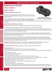
3.1.1 Determining the Total Area Required for <strong>Installation</strong>Figures 3.1 to 3.4 provide drive dimensions for enclosures A through D as an aid incalculating the total area required by the <strong>SP500</strong> drives. Appendix A lists drive weights146.0 mm (5.57”)121.9 mm (4.8”)20.7 mm (0.81”)263.5 mm (10.37”)304.8 mm (12.00”)73.0 mm (2.88”).Figure 3.1 – Enclosure A DimensionsFigure 3.2 – Enclosure B Dimensions3-2 <strong>SP500</strong> <strong>AC</strong> <strong>Drive</strong> <strong>Installation</strong> <strong>and</strong> <strong>Operation</strong> Manual Version 3.1
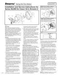
Figure 3.3 – Enclosure C DimensionsFigure 3.4 – Enclosure D Dimensions<strong>SP500</strong> System Planning 3-3
3.1.2 Providing Proper Air Flow ClearancesBe sure there is adequate clearance for air ventilation around the drive. For best airmovement, do not mount <strong>SP500</strong> drives directly above each other. Note that nodevices are to be mounted behind the drive. This area must be kept clear of all control<strong>and</strong> power wiring. See table 3.1 for a listing of the recommended air flow clearances.Table 3.1 – Air Flow ClearancesEnclosureA B C DMinimum distance from the sides of the drive if adjacent to non-heatproducing equipment51 mm(2”)102 mm(4”)102 mm(4”)102 mm(4”)Minimum distance from the top <strong>and</strong> bottom of the drive if adjacent tonon-heat producing equipment102 mm(4”)102 mm(4”)102 mm(4”)102 mm(4”)Minimum distance from the sides of the drive if adjacent to other drives51 mm(2”)102 mm(4”)102 mm(4”)102 mm(4”)Minimum distance from the top <strong>and</strong> bottom of the drive if adjacent toother drives254 mm(10”)254 mm(10”)254 mm(10”)102 mm(4”)3.1.3 Verifying the <strong>Drive</strong>’s Power Loss RatingWhen installing an <strong>SP500</strong> drive inside of another enclosure, you should consider thedrive’s watts loss rating shown in table 2.2. This table lists the typical full load powerloss watts value under all operating carrier frequencies. Ensure adequate ventilation isprovided based on the drive’s watts loss rating.3.2 Wiring RequirementsEvaluate the following areas of drive wiring before you do the installation: size ofavailable conduit, size of power <strong>and</strong> control wiring, <strong>and</strong> motor lead lengths.3.2.1 Verifying Conduit SizesIt is important to determine the size of the conduit openings accurately so that the wireplanned for a specific entry point will fit through the opening. Figures 4.1 through 4.4show conduit opening sizes.3.2.2 Recommended Power Wire SizesSize input power wiring according to applicable codes to h<strong>and</strong>le the drive’scontinuous-rated input current. Size output wiring according to applicable codes toh<strong>and</strong>le the drive’s continuous-rated output current. Tables 3.2, 3.3, <strong>and</strong> 3.4 providerecommended power wiring sizes. Use only copper wire with a minimum temperaturerating of 60/75°C. Table 3.5 contains the recommended tightening torque values for allpower wiring terminals.3-4 <strong>SP500</strong> <strong>AC</strong> <strong>Drive</strong> <strong>Installation</strong> <strong>and</strong> <strong>Operation</strong> Manual Version 3.1
.Table 3.2 – Recommended Power Wire Sizes for M/N 1SU1xxxx <strong>and</strong> 1SU2xxxx <strong>Drive</strong>sType of WiringTerminalsSize of Wire(maximum)*<strong>AC</strong> Input Power R, S, T 14 AWG, 2 (mm 2 )Output Power U, V, W 14 AWG, 2 (mm 2 )DC Bus – , + 14 AWG, 2 (mm 2 )Ground GND 14 AWG, 2 (mm 2 )*Except for M/N 1SU21002 (single-phase input), 1SU21005, <strong>and</strong> 1SU24005, for which 12 AWG, 3 (mm 2 )wire is recommended.Table 3.3 – Recommended Power Wire Sizes for M/N 1SU4xxxx <strong>and</strong> 1SU5xxxx <strong>Drive</strong>sType of WiringTerminalsSize of Wire(maximum)*<strong>AC</strong> Input Power R(L1), S(L2), T(L3) 14 AWG, 2 (mm 2 )Output Power U(T1), V(T2), W(T3) 14 AWG, 2 (mm 2 )DC Bus – , + 14 AWG, 2 (mm 2 )Snubber Resistor +10 VDC, 10 COM 14 AWG, 2 (mm 2 )Ground GND 14 AWG, 2 (mm 2 )* Except for M/N 1SU41010 <strong>and</strong> 1SU44010, for which 12 AWG, 3 (mm 2 ) wire is recommended.Table 3.4 – Recommended Power Wire Sizes for M/N 1SU4x015 <strong>and</strong> 1SU4x020 <strong>Drive</strong>sType of WiringTerminalsSize of Wire(maximum)<strong>AC</strong> Input Power R/L1, S/L2, T/L3 12 AWG, 3 (mm 2 )Output Power U/T1, V/T2, W/T3 12 AWG, 3 (mm 2 )DC Bus – , + 12 AWG, 3 (mm 2 )Snubber Resistor –, + 12 AWG, 3 (mm 2 )Ground GND 12 AWG, 3 (mm 2 )Table 3.5 – Recommended Power Terminal Tightening Torque<strong>Drive</strong>s Terminals Maximum Tightening TorqueAll All power wires 1.08 Newton-meters (9.5 in-lb)<strong>SP500</strong> System Planning 3-5
3.2.3 Recommended Control <strong>and</strong> Signal Wire SizesTable 3.6 shows the recommended wire sizes to connect I/O signals to the terminalstrip on the Regulator board. The minimum wire insulation rating is 600V. Operatorcontrols can be up to 303 meters (1000 feet) from the <strong>SP500</strong> drive. All signal wiresshould be twisted-pair.Table 3.6 – Recommended Control <strong>and</strong> Signal Wire Sizes <strong>and</strong> Tightening Torque<strong>Drive</strong>sTerminalsMinimumWire SizeMaximumWire SizeMaximumTightening TorqueAll 1–16 20 AWG,0.5 (mm 2 )14 AWG,2 (mm 2 )0.5 Newton-meters(4.5 in-lb)3.2.4 Recommended Motor Lead LengthsThe following motor lead lengths are recommended to reduce line disturbances <strong>and</strong>noise. See figure 3.5.• For applications using one motor, motor lead length should not exceed 76 meters(250 feet).• For applications with multiple motors, total motor lead length should not exceed 76meters (250 feet).When total lead length exceeds 76 meters (250 feet), nuisance trips can occur,caused by capacitive current flow to ground. Note that these capacitively-coupledcurrents should be taken into consideration when working in areas where drives arerunning. If the motor lead length must exceed these limits, the addition of output linereactors or other steps must be taken to correct the problem. See tables 3.7 <strong>and</strong> 3.8.Note that the motor lead lengths shown in table 3.7 are maximum distances. Yourapplication may be restricted to a shorter motor lead length due to:• the type of wire• the placement of the wire (for example, in conduit or a cable tray)• the type of line reactor• the type of motor<strong>SP500</strong> <strong>Drive</strong><strong>SP500</strong> <strong>Drive</strong><strong>SP500</strong> <strong>Drive</strong><strong>SP500</strong> <strong>Drive</strong>38m (125’)38m (125’)15m (50’)Motor61m (200’)61m (200’)76m (250’)MotorMotor8m (25’) 8m (25’)MotorMotorMotorMotorAll examples represent 76m (250’) of motor lead length.Figure 3.5 – How to Measure Motor Lead Lengths3-6 <strong>SP500</strong> <strong>AC</strong> <strong>Drive</strong> <strong>Installation</strong> <strong>and</strong> <strong>Operation</strong> Manual Version 3.1
1. Note that the lead lengths listed are valid with <strong>Reliance</strong> <strong>Electric</strong> inverter duty motors.2. N/A indicates that the drive does not have this rating or it is not applicable..<strong>SP500</strong> HPRatingFilter TypeTable 3.7 – Motor Lead LengthsMaximum LeadLength in Feet with230 V<strong>AC</strong> MotorMaximum LeadLength in Feet with460 V<strong>AC</strong> Motor1. MTE st<strong>and</strong>ard reactors can be used on <strong>SP500</strong> drives with carrier frequency settings up to 8 kHz.2. All reactors listed are UL-recognized (UL-506 File #E53094) <strong>and</strong> CSA certified (CSA File #LR29753).Maximum LeadLength in Feet with575 V<strong>AC</strong> MotorCarrier Frequency Carrier Frequency Carrier Frequency4 kHz 6 kHz 8 kHz 4 kHz 6 kHz 8 kHz 4 kHz 6 kHz 8 kHz1500 500 500 250 250 250 150 150 1502 500 500 500 350 350 350 250 200 2003 1000 1000 1000 400 400 400 250 200 200None5 1000 1000 1000 500 500 500 250 200 2007.5 to 10 N/A N/A N/A 500 500 500 250 250 25015 to 20 N/A N/A N/A 500 500 500 N/A N/A N/A1500 500 500 500 500 500A reactor/filter is not2 required. Above lead 500 500 500 500 500 5003 A 5% MTE lengths are maximum 1000 1000 1000 1000 1000 1000reactor/filter at the distances.5 drive.1000 1000 1000 1000 1000 10007.5 to 10 N/A N/A N/A 1000 1000 1000 1000 1000 100015 to 20 N/A N/A N/A 1000 1000 1000 N/A N/A N/ATable 3.8 – Reactors<strong>SP500</strong> HP Rating230 Volt5% MTE Reactor480 Volt5% MTE Reactor600 Volt5% MTE Reactor1 RL-00402 RL-00202 RL-002032 RL-00403 RL-004043 RL-00403 RL-004045 RL-00803 RL-008047.5 RL-01203 RL-0080310 RL-01803 RL-0120315 RL-0250320 RL-03503<strong>SP500</strong> System Planning 3-7
3.3 Selecting Input <strong>AC</strong> Line Branch Circuit Fuses!ATTENTION: Most codes require that upstream branch circuit protectionbe provided to protect input power wiring. Install the fuses recommendedin table 3.9. Do not exceed the fuse ratings.Input line branch circuit protection fuses must be used to protect the input power lines.See figure 5.1. Table 3.9 shows recommended fuse values. These fuse ratings areapplicable for one drive per branch circuit. No other load may be applied to that fusedcircuit. Note that contactors <strong>and</strong> circuit breakers are not recommended for <strong>AC</strong> inputline branch protection.Table 3.9 – <strong>AC</strong> Input Line Fuse Selection ValuesModelNumberFuseRating*ModelNumberFuseRating*ModelNumberFuseRating*1SU11001 20A 1SU41001 6A 1SU51001 4A1SU14001 12A 1SU44001 6A 1SU54001 4A1SU41002 8A 1SU51002 7A1SU21001 10A 1SU44002 8A 1SU54002 7A1SU24001 10A 1SU41003 12A 1SU51003 10A1SU21002 30A 1SU44003 12A 1SU54003 10A1SU41005 25A 1SU51005 15A1SU21001 12A 1SU44005 25A 1SU54005 15A1SU24001 12A 1SU41007 25A 1SU51007 20A1SU21002 20A 1SU44007 25A 1SU54007 20A1SU24002 20A 1SU41010 35A 1SU51010 25A1SU21003 25A 1SU44010 35A 1SU54010 25A1SU24003 25A 1SU41015 45A1SU21005 35A 1SU42015 45A1SU24005 35A 1SU41020 55A1SU42020 55A* Recommended fuse type: UL Class J, 600V, time-delay, or equivalent.3-8 <strong>SP500</strong> <strong>AC</strong> <strong>Drive</strong> <strong>Installation</strong> <strong>and</strong> <strong>Operation</strong> Manual Version 3.1
3.4 Installing an Emergency Stop!ATTENTION: The user must provide an external, hardwired emergencystop circuit outside of the drive circuitry. This circuit must disable thesystem in case of improper operation. Uncontrolled machine operationmay result if this procedure is not followed.Depending upon the requirements of the application, the <strong>SP500</strong> drive can beprogrammed to provide either a coast-to-rest (default) or a ramp-to-rest (user-option)operational stop without physical separation of the power source from the motor. Referto sections 5.2 <strong>and</strong> 8.3 (parameter F-16) for more information on how to program anoperational stop.In addition to the operational stop, users must provide a hardwired emergency stopexternal to the drive. The emergency stop circuit must contain only hardwiredelectromechanical components. <strong>Operation</strong> of the emergency stop must not depend onelectronic logic (hardware or software) or on the communication of comm<strong>and</strong>s over anelectronic network or link.3.4.1 Complying with Machinery Safety St<strong>and</strong>ard EN 60204-1:1992This section applies to users who must comply with machinery safety st<strong>and</strong>ardEN 60204-1:1992, part 9.2.5.4, Emergency Stop.The <strong>SP500</strong> drive coast-to-rest stop is a category 0 operational stop.The ramp-to-reststop is a category 1 operational stop.The required external hardwired emergency stop must be either a category 0 or 1stop, depending on the user’s risk assessment of the associated machinery. In orderto fully comply with machinery safety st<strong>and</strong>ard EN 60204-1:1992, part 9.2.5.4, at leastone of the two stop methods must be a category 0 stop. Refer to Appendix D for moreinformation.3.5 Motor ConsiderationsTo obtain motor nameplate horsepower, the drive’s output current rating at theselected carrier frequency should be equal to or greater than motor nameplatecurrent. If the motor nameplate current rating is higher than the drive’s output currentrating, derate motor horsepower by the ratio of the drive’s output ampere rating (at theselected carrier frequency) to the motor nameplate current. Note that thisapproximation is only accurate if the drive <strong>and</strong> the motor have nearly the same rating.3.5.1 Single-Motor ApplicationsSize the drive <strong>and</strong> motor for the load <strong>and</strong> speed requirements of the specificapplication.The motor’s operating current must not exceed the drive’s rated output current (at theselected carrier frequency). In addition, the motor’s horsepower rating (for example, 1,2, 3, 5, 7, 10, 15, <strong>and</strong> 20 HP) must not be more than one horsepower range largerthan the drive’s horsepower rating.<strong>SP500</strong> System Planning 3-9
If the motor will be operated below one-half of its rated speed, the motor overloadrelay may not protect the motor because of reduced cooling action due to the reducedspeed. A motor thermostat, internal to the motor, should be installed to monitor theactual temperature of the windings.3.5.2 Multiple-Motor ApplicationsOne drive can run two or more motors. Adhere to the following requirements to assurecorrect drive operation in this case:• When starting <strong>and</strong> stopping all the motors at the same time (using the drive forstarting <strong>and</strong> stopping), the sum of the full-load sine wave currents of all the motorsmust be equal to or less than the maximum sine wave output current at the selectedcarrier frequency for the drive.For example: I FLA + I FLA + I FLA = I TLA(Motor 1) (Motor 2) (Motor 3) (Total Load)Where: I TLA
CHAPTER 4Installing the <strong>Drive</strong>This chapter shows how to mount the <strong>SP500</strong> drive <strong>and</strong> its external components. Alsoshown are the entry areas for routing wiring in <strong>and</strong> out of the drive.4.1 Mounting the <strong>Drive</strong>Attach the drive to the selected flat, vertical surface using the mounting holesprovided. Enclosure A drives have two mounting holes, which are accessible after thecover is removed. Enclosure B, C, <strong>and</strong> D drives have four mounting holes. In order tomaintain a flat mounting surface <strong>and</strong> to ensure that bolt tightness is maintained, usewashers under the bolt heads. Refer to figures 3.1 through 3.4 for drive mountingdimensions. Use the following user-supplied mounting bolts <strong>and</strong> washers:• Enclosure A drives: two M6 (1/4”)• Enclosure B drives: four M8 (5/16”)• Enclosure C drives: four M8 (5/16”)• Enclosure D drives: four M8 or M10 (5/16” or 3/8”)4.2 Routing WiresAll wiring should be installed in conformance with the applicable local, national, <strong>and</strong>international codes (e.g., NEC/CEC). Signal wiring, control wiring, <strong>and</strong> power wiringmust be routed in separate conduits to prevent interference with drive operation. Donot route wires behind the drive. Use grommets when hubs are not provided to guardagainst wire chafing. Figures 4.1 through 4.4 show the wire routing, groundingterminal, <strong>and</strong> power terminal strips of the <strong>SP500</strong> drives.!ATTENTION: Do not route signal <strong>and</strong> control wiring in the same conduitwith power wiring. This can cause interference with drive operation.Do not route more than three sets of motor leads through a single conduit. This willminimize cross-talk that could reduce the effectiveness of noise reduction methods. Ifmore than three drive/motor connections per conduit are required, you must useshielded cable. If possible, each conduit should contain only one set of motor leads.!ATTENTION: Unused wires in conduit must be grounded at both endsto avoid a possible shock hazard caused by induced voltages. Also, if adrive sharing a conduit is being serviced or installed, all drives using thisconduit should be disabled to eliminate the possible shock hazard fromcross-coupled motor leads.Installing the <strong>Drive</strong> 4-1
.Figure 4.1 – Enclosure A Wire Routing Locations4-2 <strong>SP500</strong> <strong>AC</strong> <strong>Drive</strong> <strong>Installation</strong> <strong>and</strong> <strong>Operation</strong> Manual Version 3.1
Figure 4.2 – Enclosure B Wire Routing LocationsInstalling the <strong>Drive</strong> 4-3
Figure 4.3 – Enclosure C Wire Routing Locations4-4 <strong>SP500</strong> <strong>AC</strong> <strong>Drive</strong> <strong>Installation</strong> <strong>and</strong> <strong>Operation</strong> Manual Version 3.1
Figure 4.4 – Enclosure D Wire Routing LocationsInstalling the <strong>Drive</strong> 4-5
4.3 Installing External ComponentsInstall the input power <strong>and</strong> output power components that are located outside of the<strong>SP500</strong> enclosure. See figure 5.1. The following sections describe disconnect,transformer, <strong>and</strong> <strong>AC</strong> line branch protection installation.4.3.1 DisconnectsAn input disconnect (for example, a switch or circuit breaker) must be installed in theline before the drive input terminals in accordance with local, national, <strong>and</strong>international codes (e.g., NEC/CEC). Size the disconnect according to the inrushcurrent as well as any additional loads the disconnect might supply. Coordinate thetrip rating for the current (10 to 12 times the full load current) with that of the inputisolation transformer, if used. Refer to section 4.3.3 for additional information.4.3.2 Input <strong>AC</strong> Line Branch Protection!ATTENTION: Most codes require that upstream branch protection beprovided to protect input power wiring.User-supplied branch circuit protection fuses must be installed according to theapplicable local, national, <strong>and</strong> international codes (for example, NEC/CEC). The fusesmust be installed in the line before the drive’s <strong>AC</strong> input terminals. Table 3.9 providesfuse values.4.3.3 Transformers!ATTENTION: Distribution capacity above the maximum recommendedsystem KVA rating (100 KVA for 115/230 V<strong>AC</strong>, 1000 KVA for460/575 V<strong>AC</strong>) requires the use of an isolation transformer, a line reactor,or other means of adding similar impedance to the drive’s input powerwiring.ATTENTION: When the <strong>AC</strong> line is shared directly with other SCRrectifieddrives, an optional snubber resistor braking kit might be requiredto alleviate excess DC bus voltageInput isolation transformers may be needed to help eliminate the following:• Damaging line voltage transients.• Line noise from the drive back to the incoming power source.• Damaging currents that could develop if a point inside the drive becomes grounded.Observe the following guidelines when installing an isolation transformer:• A power disconnecting device must be installed between the power line <strong>and</strong> theprimary of the transformer. If the power disconnecting device is a circuit breaker, thecircuit breaker trip rating must be coordinated with the inrush current (10 to 12 timesthe full load current) of the transformer.4-6 <strong>SP500</strong> <strong>AC</strong> <strong>Drive</strong> <strong>Installation</strong> <strong>and</strong> <strong>Operation</strong> Manual Version 3.1
• Do NOT use an input isolation transformer rated more than 100 KVA for 230 V<strong>AC</strong> (or1000 KVA for 460 V<strong>AC</strong>) with less than 5% impedance directly ahead of the drivewithout additional impedance between the drive <strong>and</strong> the transformer.If your <strong>SP500</strong> application requires the use of an output transformer, contact <strong>Reliance</strong><strong>Electric</strong> for assistance.4.3.4 Output Contactors!ATTENTION: Any disconnecting means wired to drive output terminalsU, V, <strong>and</strong> W must be capable of disabling the drive if opened during driveoperation. If opened during drive operation, the drive will continue toproduce output voltage between U, V, W. An auxiliary contact must beused to simultaneously disable the drive or output component damagemay occur.Output contactors provide a positive means of disconnecting the motor from the drive.If your <strong>SP500</strong> application requires the use of output contactors, contact <strong>Reliance</strong><strong>Electric</strong> for assistance.4.3.5 Mechanical Motor Overload ProtectionTo provide the motor with overload protection, local, national, <strong>and</strong> international codes(for example, NEC/CEC) require that a motor thermostat, internal to the motor, beinstalled or an electronic thermal motor overload relay, sized to protect the motor, beinstalled between the motor <strong>and</strong> the drive’s output terminals.The Electronic Thermal Overload parameter (F-14) may be used in place of theelectronic thermal motor overload relays in single motor applications. Note, however,that temperature-sensing devices integral to the motor are the best way of thermallyprotecting<strong>AC</strong> motors under all conditions. Parameter F-14 must be enabled to provideoverload protection. Refer to section 8.3 for the parameter description.In multiple motor applications, each motor must have its own user-supplied overloadprotection.4.4 Setting the Analog Input Jumper on the RegulatorBoard<strong>SP500</strong> drives have an analog speed reference input. This is a jumper-selectable 0 to10 VDC or 0 to 20 mA input with programmable gain <strong>and</strong> offset adjustments(parameters F-11 <strong>and</strong> F-12). Jumper J6 on the Regulator board is set to match thetype of incoming analog signal, either voltage or current. See figures 2.2, 4.5, <strong>and</strong> 5.3.Refer to section 5.2.1 for more information.Installing the <strong>Drive</strong> 4-7
1 2 3 4 5 6 7 8 9 10 11 12 13 14 15 16J60-20 mA0-10 VDCFigure 4.5 – Jumper J6 Settings for the Analog Input Speed ReferenceUse the following procedure to set jumper J6:!ATTENTION: DC bus capacitors retain hazardous voltages after inputpower has been disconnected. After disconnecting input power, wait five(5) minutes for the DC bus capacitors to discharge <strong>and</strong> then check thevoltage with a voltmeter to ensure the DC bus capacitors are dischargedbefore touching any internal components.Step 1. Turn off <strong>and</strong> lock out input power. Wait five minutes.Step 2. Remove the cover from the drive by unscrewing the four cover screws.Step 3. Verify that the DC bus voltage is zero by following the procedure in section9.1.Step 4. Locate jumper J6 on the Regulator board. Refer to figure 2.3.Step 5. Move the jumper to the desired setting as shown in figure 4.5.Step 6. Reattach the cover.Step 7. Reapply input power.Step 8. Verify that parameters F-11 <strong>and</strong> F-12 are correctly set.Note that if the setting of jumper J6 is changed, the regulator software will notautomatically detect it. Verify that parameters F-11 (gain) <strong>and</strong> F-12 (offset) are setcorrectly before starting the drive.4.5 Preparing the MotorFollow these guidelines when preparing to install the motor:• Verify that the motor is the appropriate size to use with the drive.• Verify that the total motor lead length does not exceed the values given in section3.2.4.• Follow the instructions in the motor instruction manual when installing the motor.4-8 <strong>SP500</strong> <strong>AC</strong> <strong>Drive</strong> <strong>Installation</strong> <strong>and</strong> <strong>Operation</strong> Manual Version 3.1
• Verify that the motor is properly aligned with the application’s machine to minimizeunnecessary motor loading due to shaft misalignment.• If the motor is accessible when it is running, install a protective guard around allexposed rotating parts.Installing the <strong>Drive</strong> 4-9
4-10 <strong>SP500</strong> <strong>AC</strong> <strong>Drive</strong> <strong>Installation</strong> <strong>and</strong> <strong>Operation</strong> Manual Version 3.1
CHAPTER 5Wiring the <strong>Drive</strong>This chapter describes how to wire the <strong>SP500</strong> drive including: input wiring, control <strong>and</strong>signal wiring, output wiring, <strong>and</strong> grounding.5.1 Input Power WiringUse the following steps to connect <strong>AC</strong> input power to the drive:Step 1. Verify that the <strong>AC</strong> input power to the drive corresponds to the drive’snameplate voltage <strong>and</strong> frequency.Step 2. Wire the <strong>AC</strong> input power leads by routing them according to the type ofenclosure. See figures 4.1 through 4.4. See tables 3.2 through 3.4 forrecommended wire sizes..!ATTENTION: Do not route signal <strong>and</strong> control wiring with power wiring inthe same conduit.This can cause interference with drive operation.Step 3.Step 4.Connect the <strong>AC</strong> input power leads to terminals R,S,T on the power terminalstrip. See figure 5.1.Tighten terminals R <strong>and</strong> S (single-phase input) or terminals R,S,T (threephaseinput) to the proper torque as shown in table 3.5.Wiring the <strong>Drive</strong> 5-1
<strong>AC</strong> InputVoltageGNDManualDisconnectFuseUser-SuppliedR/L1 S/L2 T/L3~-GND<strong>SP500</strong><strong>Drive</strong>-~User-SuppliedU/T1Motor Overload Relay(Optional if Electronic Overload is Used)UUV/T2 W/T3UUUUGNDMFigure 5.1 – Typical <strong>Electric</strong>al Connections5-2 <strong>SP500</strong> <strong>AC</strong> <strong>Drive</strong> <strong>Installation</strong> <strong>and</strong> <strong>Operation</strong> Manual Version 3.1
5.2 Signal <strong>and</strong> Control WiringThe terminal strip on the Regulator board provides terminals for connecting signal (forexample, external speed reference <strong>and</strong> analog output) <strong>and</strong> control (for example, stop,start, <strong>and</strong> function loss) wiring. See figure 5.2. Terminals for the following wireconnections are provided:• Terminals 1-3: analog speed reference connections• Terminals 4-5: analog output connections• Terminals 6-11: digital input connections• Terminals 12-13: snubber resistor connections• Terminals 14-16: output status connectionsIsolated Reference VoltageVoltage/Current Speed ReferenceIsolated Reference GroundAnalog Meter Output24 VDC CommonStopStartResetForward/ReverseFunction Loss24 VDC CommonSnubber Resistor Braking Signal24 VDC CommonRelay CommonN.O. Relay ContactN.C. Relay ContactAnalogSpeedReferenceAnalogOutputDigitalInputsSnubberResistorBrakingSignalOutputStatusRelayFigure 5.2 – Typical Control Terminal Strip Connections5.2.1 Analog Speed Reference WiringAnalog speed reference input wiring connects to terminals 1 through 3 on theRegulator board’s terminal strip. See figure 5.3. This reference signal is jumperselectablefor either a 0 to 10 VDC or 0 to 20 mA input. The setting of jumper J6 on theRegulator board determines whether the input reference is a voltage or current signal.This reference signal can be provided by either a user-supplied 5K ohm potentiometeror an external 0-10 VDC/0-20 mA supply. See section 4.4 for more information.Wiring the <strong>Drive</strong> 5-3
User-SuppliedSpeed ReferencePotentiometer+10 VDCUser-SuppliedSpeed ReferenceInput Signal0-10 VDCor0-20 mA5kΩorFigure 5.3 – Analog Speed Reference Wiring Connections5.2.2 Analog Output WiringAnalog output wiring connects to terminals 4 <strong>and</strong> 5 on the Regulator board’s terminalstrip. See figure 5.4. This is a scaled 0 to 10 VDC output signal that is proportional toeither current speed, percent of load, calculated output voltage, or percent of theselected reference value, whichever is selected through parameter F-29. This outputsignal is available during both local <strong>and</strong> remote operation.Load(User-SuppliedAnalog Meter)+10V 0VFigure 5.4 – Analog Output Wiring Connections5.2.3 Digital Input WiringDigital input wiring connects to terminals 6 through 11 on the Regulator board’sterminal strip. The drive has a 24 VDC power supply that provides the required voltagefor control signals. Enabling or disabling a control signal requires that a contact(switch) be opened or closed.Important: The 24 VDC power supply is unregulated <strong>and</strong> will nominally supply24 VDC. It is not to be used with any external devices other than theinputs to the drive.5-4 <strong>SP500</strong> <strong>AC</strong> <strong>Drive</strong> <strong>Installation</strong> <strong>and</strong> <strong>Operation</strong> Manual Version 3.1
Start <strong>and</strong> Stop Control WiringStart <strong>and</strong> stop control wiring connects to terminals 6, 7, <strong>and</strong> 11. See figures 5.5 <strong>and</strong>5.6. Note that these start/stop wiring connections are not to be used in multi-speedpreset applications which are discussed in the following section.Start/StopIETResetFwdRevFunctionLossCustomerInterlockStopStartIET ResetForward/ReverseFunction Loss24 VDC CommonFigure 5.5 – Two-Wire Start/Stop Sample Control WiringStopStartIETResetFwdRevFunctionLossCustomerInterlockStopStartIET ResetForward/ReverseFunction Loss24 VDC CommonFigure 5.6 – Three-Wire Start/Stop Sample Control WiringWiring the <strong>Drive</strong> 5-5
Multi-Speed Preset WiringMulti-speed preset wiring connects to terminals 6 through 8, <strong>and</strong> 11. See figure 5.7.When control type 3 is selected through parameter F-00, remote terminal strip controlis enabled with multi-speed presets. This mode of operation changes the functionalityof terminals 6 through 8 <strong>and</strong> may be used in place of 2- <strong>and</strong> 3-wire start/stop wiring.See figure 5.8.When you enable multi-speed preset operation, the state of terminals 7 <strong>and</strong> 8determine the source of the speed reference:Terminal 7 Terminal 8 Speed Reference Source0 0 Terminal Strip Analog Input0 1 Multi-Speed Preset 1 (Parameter F-23)1 0 Multi-Speed Preset 2 (Parameter F-24)1 1 Multi-Speed Preset 3 (Parameter F-25)Start/Stop/IET ResetMulti-Speed Preset 2Multi-Speed Preset 1FwdRevFunctionLossCustomerInterlockStart/Stop/IET ResetMulti-Speed Preset 2Multi-Speed Preset 1Forward/ReverseFunction Loss24 VDC CommonFigure 5.7 – Multi-Speed Preset Sample Control Wiring5-6 <strong>SP500</strong> <strong>AC</strong> <strong>Drive</strong> <strong>Installation</strong> <strong>and</strong> <strong>Operation</strong> Manual Version 3.1
F-00 = 0, 1, 24F-00 = 3 (Multi-Speed Presets)4Analog Meter Output24 VDC CommonStart/Stop/IET ResetMulti-Speed Preset 2Multi-Speed Preset 1Forward/ReverseFunction Loss24 VDC CommonSnubber ResistorBraking SignalAnalog Meter Output24 VDC CommonStopStartIET ResetForward/ReverseFunction Loss24 VDC CommonSnubber ResistorBraking SignalIET Reset Control WiringIET reset control wiring connects to terminals 8 <strong>and</strong> 11. See figures 5.5 <strong>and</strong> 5.6. Notethat these reset wiring connections are not to be used in multi-speed presetapplications. See figures 5.7 <strong>and</strong> 5.8.Forward/Reverse Control WiringForward/reverse control wiring connects to terminals 9 <strong>and</strong> 11. See figures 5.5through 5.7. Note that the setting of the forward/reverse switch is ignored whenparameter F-17 is equal to 1 (disable reverse operation).Function Loss Control WiringFigure 5.8 – Terminal Usage During Multi-Speed Preset <strong>Operation</strong>!ATTENTION: The user must provide an external, hardwired emergencystop circuit outside of the drive circuitry. This circuit must disable thesystem in case of improper operation. Uncontrolled machine operationmay result if this procedure is not followed.Function loss control wiring connects to terminals 10 <strong>and</strong> 11. See figures 5.5 through5.7. Typically, a function loss input is a maintained, normally-closed pushbutton.A signal must be present at terminal 10 for the drive to run. A factory-installed jumperconnects terminals 10 <strong>and</strong> 11 which provides that signal. Remove this jumper if afunction loss input, a coast-stop pushbutton, or another external interlock (forexample, a motor thermostat) is used. Removing the jumper allows the drive to stopwhen the contact is open.Wiring the <strong>Drive</strong> 5-7
5.2.4 Snubber Resistor WiringSnubber resistor wiring connects to terminals 12 <strong>and</strong> 13 on the Regulator board’sterminal strip. See figures 5.9 <strong>and</strong> 5.10.SnubberResistor<strong>Drive</strong> Model Number Terminals1SU2xxxx 1 (+)2 (–)147 (+)45 (–)1SU4xxxx & 1SU5xxxx 1 (+)2 (–)147 (+)45 (–)Control TerminalStrip Connections1213N/A1213N/APower TerminalStrip ConnectionsN/A(+) DC Bus(–) DC BusN/A(+) DC Bus(–) DC Bus13 (+)14 (–)N/A(+) 10V(–) 10 COM1SU4x015 & 1SU4x020 Refer to instruction manual D2-3291.5-8 <strong>SP500</strong> <strong>AC</strong> <strong>Drive</strong> <strong>Installation</strong> <strong>and</strong> <strong>Operation</strong> Manual Version 3.1
RegulatorBoardControlTerminalStrip12 13Snubber ResistorBraking Signal24 VDC Common+1-2+147-45Snubber ResistorBraking SignalDC Bus VoltsSnubber ResistorPowerTerminalStrip+ -DC BusVolts<strong>SP500</strong> <strong>Drive</strong>Figure 5.9 – Snubber Resistor Wiring Connections for M/N 1SU2xxxx <strong>Drive</strong>sRegulatorBoardControlTerminalStripSnubber ResistorBraking Signal12 1324 VDC Common+1-2+147-45+13-14Snubber ResistorBraking Signal 1DC Bus Volts10V Supply 1Snubber Resistor1 These connections are not used withM/N 2SRxxxx Snubber Resistor kits.PowerTerminalStrip+ -DC BusVolts+ -10V 10VCom<strong>SP500</strong> <strong>Drive</strong>Note: The 10V <strong>and</strong> 10V Com terminals on the power terminal stripdo not exist on 460 V<strong>AC</strong> 15 HP <strong>and</strong> 20 HP <strong>SP500</strong> drive models.Depending on your choice of Snubber Resistor kit, you mayneed to provide an external 10V source.Figure 5.10 – Snubber Resistor Wiring Connections for M/N 1SU4xxxx <strong>and</strong> 1SU5xxxx <strong>Drive</strong>sWiring the <strong>Drive</strong> 5-9
5.2.5 Output Status Relay WiringOutput status wiring connects to terminals 14 through 16 on the Regulator board’sterminal strip. See figure 5.11. Parameter F-09 specifies the type of status indicationprovided by the output relay. See the F-09 parameter description in section 8.3 formore information.USER-SUPPLIEDLAMPN.O.USER-SUPPLIED115 V<strong>AC</strong> / 24 VDC(10 mA Min.)14 15 165.3 Output Power WiringUse the following steps to connect <strong>AC</strong> output power wiring from the drive to the motor:Step 1. Wire the <strong>AC</strong> output power leads by routing them according to the type ofenclosure. See figures 4.1 through 4.4. See tables 3.2 through 3.4 forrecommended wire sizes..!Figure 5.11 – Output Status Relay Wiring ConnectionsATTENTION: Do not route signal <strong>and</strong> control wiring with power wiringin the same conduit. This can cause interference with drive operation.Do not route more than three sets of motor leads through a single conduit. This willminimize cross-talk which could reduce the effectiveness of noise reduction methods.If more than three drive/motor connections per conduit are required, you must useshielded cable. If possible, each conduit should contain only one set of motor leads.!ATTENTION: Unused wires in conduit must be grounded at both endsto avoid a possible shock hazard caused by induced voltages. Also, ifa drive sharing a conduit is being serviced or installed, all drives usingthis conduit should be disabled to eliminate the possible shock hazardfrom cross-coupled motor leads.Step 2. Connect the <strong>AC</strong> output power motor leads to terminals U, V, <strong>and</strong> W on thepower terminal strip. See figure 5.1.Step 3. Tighten terminals U, V, <strong>and</strong> W to the proper torque as shown in table 3.5.5-10 <strong>SP500</strong> <strong>AC</strong> <strong>Drive</strong> <strong>Installation</strong> <strong>and</strong> <strong>Operation</strong> Manual Version 3.1
5.4 Grounding!ATTENTION: The user is responsible for conforming with all applicablelocal, national, <strong>and</strong> international codes.Use the following steps to ground the drive:Step 1. Remove the drive’s cover.Step 2. Run a suitable equipment grounding conductor unbroken from the drive’sground terminal to the motor’s ground terminal <strong>and</strong> then to earth ground. Seefigures 4.1 through 4.4 <strong>and</strong> 5.1.Step 3. Connect a suitable grounding connector to the motor frame <strong>and</strong> transformer(if used). Run each conductor unbroken to earth ground.When adding more than one grounding conductor wire to a single chassisground, twist the conductors together.Step 4. Reattach the drive’s cover.Wiring the <strong>Drive</strong> 5-11
5-12 <strong>SP500</strong> <strong>AC</strong> <strong>Drive</strong> <strong>Installation</strong> <strong>and</strong> <strong>Operation</strong> Manual Version 3.1
CHAPTER 6Completing the <strong>Installation</strong>This chapter provides procedures to check the installation.!ATTENTION: Only qualified electrical personnel familiar with theconstruction <strong>and</strong> operation of this equipment <strong>and</strong> the hazards involvedshould install, adjust, operate, <strong>and</strong>/or service this equipment. Read <strong>and</strong>underst<strong>and</strong> this manual in its entirety before proceeding.6.1 Checking the <strong>Installation</strong> With the Power Off!ATTENTION: DC bus capacitors retain hazardous voltages after inputpower has been disconnected. After disconnecting input power, wait five(5) minutes for the DC bus capacitors to discharge <strong>and</strong> then check thevoltage with a voltmeter to ensure the DC bus capacitors are dischargedbefore touching any internal components.Perform the following checks of the drive installation with the power off:Step 1. Turn off, lock out, <strong>and</strong> tag the input power to the drive. Wait five minutes.Step 2. Check the DC bus potential with a voltmeter as described in section 9.1 toensure that the DC bus capacitors are discharged.Step 3. If an input disconnect is installed, make sure it is in the off position.Step 4. Make sure the drive interlocks installed around the driven machine areoperational.!Step 5.!Step 6.Step 7.Step 8.ATTENTION: The user must provide an external, hardwired emergencystop circuit outside of the drive circuitry. This circuit must disable thesystem in case of improper operation. Uncontrolled machine operationmay result if this procedure is not followed.Verify that the user-installed stop pushbutton is wired correctly. Be sure thefactory-installed jumper at terminals 10 <strong>and</strong> 11 has been removed so that thecoast-stop pushbutton will work. (Refer to section 5.2.3.)ATTENTION: Make sure electrical commons are not intermixed in thedrive.Remove any debris from around the drive.Check that there is adequate clearance around the drive.Verify that the wiring to the control terminal strip <strong>and</strong> power terminals iscorrect. Refer to chapter 5.Completing the <strong>Installation</strong> 6-1
Step 9. Check that the wire sizes are within terminal specifications <strong>and</strong> that theterminals are tightened to the appropriate torque specifications. Refer totables 3.2 through 3.6.Step 10. Check that the user-supplied branch circuit protection is installed <strong>and</strong>correctly rated.Step 11. Check that the incoming <strong>AC</strong> power is rated correctly.Step 12. Check the motor installation <strong>and</strong> length of motor leads.Step 13. Disconnect any power correction capacitors connected between the drive<strong>and</strong> the motor.Step 14. Check that any motor thermal switch <strong>and</strong> the drive’s electronic thermaloverload are enabled (parameter F-15 = ON).Step 15. Check that the rating of the transformer (if used) matches the driverequirements <strong>and</strong> is connected for the proper voltage.Step 16. Verify that a properly-sized ground wire is installed <strong>and</strong> that a suitable earthground is used. Check for <strong>and</strong> eliminate any grounds between the motorframe <strong>and</strong> the motor power leads. Verify that all ground leads are unbroken.Step 17. Uncouple the motor from any driven machinery to initially start the drive.6.2 Checking <strong>Drive</strong> <strong>Operation</strong>!ATTENTION: DC bus capacitors retain hazardous voltages after inputpower has been disconnected. After disconnecting input power, wait five(5) minutes for the DC bus capacitors to discharge <strong>and</strong> then check thevoltage with a voltmeter to ensure the DC bus capacitors are dischargedbefore touching any internal componentsUse the following procedure to check the operation of the drive:Step 1. Turn off, lock out, <strong>and</strong> tag power to the drive. Wait five minutes.Step 2. Remove the cover <strong>and</strong> check the DC bus potential with a voltmeter asdescribed in section 9.1. Verify that the DC bus capacitors are discharged.Replace the cover.Step 3. Uncouple the driven equipment from the motor, if possible.Step 4. Apply power to the drive. SELF should be displayed for approximately 1 to 2seconds to indicate internal diagnostics are being performed. After 1 to 2seconds, 0 should be displayed <strong>and</strong> the LEDs should indicate drive status. Ifany fault codes are displayed, refer to chapter 9, Troubleshooting Reference.Step 5. Check all parameter settings <strong>and</strong> verify that they are set correctly based onthe application. In most cases, the factory default values are adequate forthis no-load start-up test. Parameters are described in chapter 8.Step 6. Press the START key. The drive should ramp at the acceleration rate (F-01)until it reaches the preset minimum speed (F-03).6-2 <strong>SP500</strong> <strong>AC</strong> <strong>Drive</strong> <strong>Installation</strong> <strong>and</strong> <strong>Operation</strong> Manual Version 3.1
Step 7.Verify the direction of the motor shaft rotation. If it is incorrect for yourapplication, use the following procedure to change the direction of rotation. Ifit is correct, go to step 8.a. Press the STOP/RESET key to stop the drive.b. Wait until the motor has completely stopped.c. Turn off, lock out, <strong>and</strong> tag power to the drive. Wait five minutes.d. Remove the cover <strong>and</strong> check the DC bus potential with a voltmeter asdescribed in section 9.1. Verify that the DC bus capacitors are discharged.Replace the cover.e. Reverse any two of the three motor power leads (U, V, or W).f. Turn the power on.g. Press the START key <strong>and</strong> verify the direction of rotation.Step 8. Using the <strong>and</strong> keys, run the motor without any load across thespeed range. If the motor does not operate satisfactorily, check theparameter settings. Refer to chapter 8.Step 9. Press the STOP/RESET key to stop the drive.Step 10. Turn off, lock out, <strong>and</strong> tag power to the drive. Wait five minutes. Remove thecover <strong>and</strong> check the DC bus potential with a voltmeter as described insection 9.1. Verify that the DC bus capacitors are discharged. Replace thecover.Step 11. Couple the driven equipment to the motor.Step 12. Turn power on.Step 13. Press the START key.Step 14. Run the drive across the required speed range under load. If the motor doesnot rotate at minimum speed, increase the manual torque boost (F-06).Step 15. If the drive operates the motor properly, go to step 16. If the drive does notoperate the motor properly, follow the steps below:a. Refer to chapter 9, Troubleshooting Reference, if any fault codes weredisplayed during start up.b. Verify the parameter settings again.Step 16. If the drive operates the motor properly:a. Press the STOP/RESET key to stop the drive.b. Record the parameter settings in Appendix B.Completing the <strong>Installation</strong> 6-3
6-4 <strong>SP500</strong> <strong>AC</strong> <strong>Drive</strong> <strong>Installation</strong> <strong>and</strong> <strong>Operation</strong> Manual Version 3.1
CHAPTER 7Keypad <strong>and</strong> Display <strong>Operation</strong>The front-panel keypad <strong>and</strong> display, shown in figure 7.1, are used to program, monitor,<strong>and</strong> control the drive. They operate in two modes: monitor mode <strong>and</strong> program mode.In monitor mode (the default mode), you can monitor specific drive outputs <strong>and</strong> thedrive’s speed reference.In program mode, you can view <strong>and</strong> adjust drive parameter values <strong>and</strong> examine theerror log.In addition to the functions above, if the control source is local (F-00 = 0), you use thekeypad to start <strong>and</strong> stop the drive, select motor direction, <strong>and</strong> adjust speed.Regardless of the control source selected, you can use the keypad to stop the drive<strong>and</strong> reset drive faults.The following sections describe the keypad, the display, <strong>and</strong> the LEDs. Monitor mode<strong>and</strong> program mode are described in more detail later in this chapter.RPM%LoadVoltsRemoteRUNProgramForwardReverseModeEnterSTARTForwardReverseSTOPRESET7.1 Display DescriptionFigure 7.1 – <strong>SP500</strong> Keypad <strong>and</strong> DisplayThe display is a four-character, seven-segment LED. At drive power up, SELF isdisplayed while the drive performs power-up diagnostics. During drive operation, thedisplay indicates parameter numbers, parameter values, fault codes, <strong>and</strong> drive outputvalues. Figures 7.3 <strong>and</strong> 7.4 show sample displays.Keypad <strong>and</strong> Display <strong>Operation</strong> 7-1
7.2 Key DescriptionsThe keypad’s six membrane keys are used to monitor, program, <strong>and</strong> control the drive.Table 7.1 describes the keys.Table 7.1 – Key DescriptionsUse the UP <strong>and</strong> DOWN arrow keys to:• Step through the drive parameters <strong>and</strong> error log when the drive is in program mode.• Increase or decrease a parameter’s numeric value or status in program mode.• Increase or decrease the internal speed reference when F-00 (Control Source Select) =0 or 2.Hold down these keys to increase the scroll speed.Use the MODE/ENTER key to:ModeEnter• Advance through each monitor display item in monitor mode.• Select program mode when the drive is stopped.• Display a parameter value in program mode.• Save a parameter value in program mode.The MODE/ENTER key provides these functions regardless of the control source selected(local or remote).ForwardReverseUse the FORWARD/REVERSE key to select the direction of motor shaft rotation when thecontrol source is local (F-00 = 0).Use the START key to apply power to the motor when the control source is local (F-00 = 0).STARTWhen this key is pressed, <strong>and</strong> there are no active faults, the drive will accelerate to the lastprogrammed frequency setpoint (speed).Use the STOP/RESET key to:STOPRESET• Turn off the drive output to the motor if the drive is running.• Clear drive faults when the drive is in program mode.• Exit program mode.When this key is pressed, the drive will ramp to rest at a user-defined rate (user option) orcoast to rest (default). This key stops the drive regardless of the selected control source(remote or local).7-2 <strong>SP500</strong> <strong>AC</strong> <strong>Drive</strong> <strong>Installation</strong> <strong>and</strong> <strong>Operation</strong> Manual Version 3.1
7.3 LED DescriptionsThe keypad area contains eight LEDs that indicate either drive status or which driveoutput value is displayed in monitor mode. Tables 7.2 <strong>and</strong> 7.3 describe the drive statusLEDs <strong>and</strong> monitor mode LEDs, respectively.Table 7.2 – <strong>Drive</strong> Status LED DescriptionsLED State DescriptionRunOnOffThe drive is generating an output voltage <strong>and</strong>frequency.The drive is not generating an output voltage <strong>and</strong>frequency.!ATTENTION:The RUN LED must not be used as an indication thatthere is no line voltage present in the drive. Verify there is no voltagepresent at the DC bus terminals (+) <strong>and</strong> (–) before servicing the drive.Failure to observe this precaution could result in severe bodily injuryor loss of life.ProgramForwardReverseRemoteOnOffOnOffOnOffOnOffThe keypad <strong>and</strong> display are in program mode.The keypad <strong>and</strong> display are in monitor mode.The requested motor rotation direction is forward.The requested motor rotation direction is not forward.The requested motor rotation direction is reverse.The requested motor rotation direction is not reverse.The drive is being controlled from the terminal strip.The drive is being controlled from the keypad.Table 7.3 – Monitor Mode LED DescriptionsLEDRPM/EngineeringUnit%LoadVoltsAll LEDs (RPM, Volts,%Load)Corresponding Display When LED is On(Actual Value)Motor speed in RPM or in a user-specified engineeringunit. (Refer to the F-08 parameter description for moreinformation).Percentage of drive full load amps rating.<strong>Drive</strong> output voltage to the motor.Value of the active speed reference signal as 0 to 100% ofthe total scaled reference range. F-13 must be set to ONto display this value. (Refer to the F-13 parameterdescription for more information).Keypad <strong>and</strong> Display <strong>Operation</strong> 7-3
7.4 Program ModeProgram mode allows you to display <strong>and</strong> modify drive parameter values when thedrive is stopped.The following can be displayed in program mode:• Parameter numbers• Parameter values• Error log informationTo enter program mode:Step 1. Stop the drive (if it is running) by pressing the STOP/RESET key.Step 2. Press the MODE/ENTER key until the PROGRAM LED turns on.Parameter F-00 will be displayed. Use the key or key to scroll through theparameter list. The error log follows parameter F-49 <strong>and</strong> precedes parameter F-00 asshown in figure 7.2.F-00F-01F-02F-49ErrFigure 7.2 – <strong>SP500</strong> Menu StructureTo exit program mode:Step 1. Press the MODE/ENTER key until a parameter number or ERR is displayed.Step 2. Press the STOP/RESET key until the PROGRAM LED turns off.Important: Pressing the STOP/RESET key while you are examining the error logclears the log.7-4 <strong>SP500</strong> <strong>AC</strong> <strong>Drive</strong> <strong>Installation</strong> <strong>and</strong> <strong>Operation</strong> Manual Version 3.1
A sample program mode display is shown in figure 7.3.RPM%LoadVoltsRemoteRUNProgramForwardReverseModeEnterSTARTForwardReverseSTOPRESETFigure 7.3 – Example of a Program Mode DisplayFor information about:Refer to section:Displaying or changing parameter values 8.1Ensuring program security 8.2Individual parameters 8.3Accessing the error log 9.47.5 Monitor ModeMonitor mode is the keypad <strong>and</strong> display’s default mode of operation (in other words,the keypad <strong>and</strong> display will return to monitor mode when you exit program mode). Thekeypad <strong>and</strong> display must be in monitor mode before the drive can be put into run (RUNLED is on) <strong>and</strong> will remain in monitor mode while the drive is running.The following output data can be displayed in monitor mode:• RPM• %Load• Volts• Percent Selected Speed Reference (if F-13 = ON)To select a value to monitor, press the MODE/ENTER key until the LED turns on nextto the desired display item. Pressing the MODE/ENTER key will advance you througheach of the displays. (Note that all the LEDs will turn on to indicate the percentselected speed reference display if parameter F-13 is set to ON. Refer to section7.5.2.)Keypad <strong>and</strong> Display <strong>Operation</strong> 7-5
A sample monitor mode display is shown in figure 7.4.RPM%LoadVoltsRemoteRUNProgramForwardReverseModeEnterSTARTForwardReverseSTOPRESETFigure 7.4 – Example of a Monitor Mode Display7.5.1 Displaying the Percent Selected Speed ReferenceTo display the percent selected speed reference, parameter F-13 must be set to ON.Use the following procedure to display the percent selected speed reference:Step 1. Stop the drive (if it is running) by pressing the STOP/RESET key.Step 2. Enter program mode by pressing the MODE/ENTER key until the PROGRAMLED turns on.Step 3. Press the or key until F-13 is displayed.Step 4. Press the MODE/ENTER key to access the parameter.Step 5. Press the key until ON is displayed.Step 6. Press the MODE/ENTER key to save the value. (F-13 will be displayed.)Step 7. Press the STOP/REST key to exit program mode.Step 8. Start the drive by pressing the START key.Step 9. Press the MODE/ENTER key until all three monitor mode LEDs are on.The display will show the active speed reference as 1 to 100% of maximum speed(F-04).7.5.2 Scaling the RPM Display <strong>and</strong> Reference Using F-08The RPM display <strong>and</strong> reference can be scaled to an engineering unit to match yourapplication. Refer to the F-08 description in chapter 8 for this procedure.7.6 <strong>Drive</strong> ControlWhen the control source is the local keypad (F-00 = 0), the keypad is used to controlthe drive. This means that the drive will respond to START, STOP/RESET, <strong>and</strong>FORWARD/REVERSE comm<strong>and</strong>s only from the keypad.7-6 <strong>SP500</strong> <strong>AC</strong> <strong>Drive</strong> <strong>Installation</strong> <strong>and</strong> <strong>Operation</strong> Manual Version 3.1
The functions of the keypad keys are described in section 7.2. Refer to the F-00Control Source Select parameter description in chapter 8 for more information onselecting a drive control source.7.6.1 Changing the Reference Using the KeypadThe speed reference can be increased or decreased using the or key whenF-00 = 0 or 2. The display will show the internal speed reference in hertz (Hz) whilethe keys are pressed. There will be a slight delay before the display returns to theactive monitor mode.Note that changing the drive’s internal speed reference using the or keywhen the drive is under remote control will have no operational effect on the drive(unless F-00 = 2).Keypad <strong>and</strong> Display <strong>Operation</strong> 7-7
7-8 <strong>SP500</strong> <strong>AC</strong> <strong>Drive</strong> <strong>Installation</strong> <strong>and</strong> <strong>Operation</strong> Manual Version 3.1
CHAPTER 8Programming ReferenceTo program the <strong>SP500</strong> drive for a specific application, you display the appropriateparameter <strong>and</strong> adjust it as required. The parameters specify characteristics of thedrive. This chapter describes how to access, display, <strong>and</strong> modify parameters. Section8.3 describes each parameter in detail. Appendix C lists the parameters inalphabetical order.8.1 Displaying or Changing Parameter ValuesUse the following procedure to display or change parameter values:Step 1.Stop the drive (if it is running) by pressing the STOP/RESET key.Step 2.Enter program mode by pressing the MODE/ENTER key until thePROGRAM LED turns on.The first parameter number (F-00) will bedisplayed.RPM%LoadVoltsRemoteRUNProgramForwardReverseModeEnterSTARTForwardReverseSTOPRESETStep 3. Press the or key until the desired parameter number isdisplayed.Each parameter number will be displayed asyou scroll through the parameter list.RPM%LoadVoltsRemoteRUNProgramForwardReverseModeEnterSTARTForwardReverseSTOPRESETProgramming Reference 8-1
Step 4.Press the MODE/ENTER key to display the parameter value.RPM%LoadVoltsRemoteRUNProgramForwardReverseModeEnterSTARTForwardReverseSTOPRESETStep 5. Press the or key to change the value.RPM%LoadVoltsRemoteRUNProgramForwardReverseModeEnterSTARTForwardReverseSTOPRESETNote that if programming has been disabledin parameter F-20 (Password LockoutEnable), the value will not change. Refer tosection 8.2, Ensuring Program Security, formore information.Step 6.Press the MODE/ENTER key to save the changed value.The parameter number is displayed again.RPM%LoadVoltsRemoteRUNProgramForwardReverseModeEnterSTARTForwardReverseSTOPRESETTo display or change additional parameters, repeat steps 3 through 6.To exit program mode, press the MODE/ENTER key until a parameter number orERR is displayed; then press the STOP/RESET key.Important: Parameter values <strong>and</strong> the keypad status (local or remote) are retainedthrough a line dip or power loss.8-2 <strong>SP500</strong> <strong>AC</strong> <strong>Drive</strong> <strong>Installation</strong> <strong>and</strong> <strong>Operation</strong> Manual Version 3.1
8.2 Ensuring Program Security!ATTENTION: It is the user’s responsibility to determine how to distributethe password. <strong>Reliance</strong> <strong>Electric</strong> is not responsible for unauthorizedaccess violations within the user’s organization.Parameter values can be password-protected using parameter F-20 (PasswordLockout Enable). When F-20 is set to ON, parameter values can be displayed butcannot be modified from the keypad unless the correct password is entered in F-20.Important: The password is factory set to 257 <strong>and</strong> cannot be modified by the user.Use the following procedure to disable or enable parameter programming:Step 1. In program mode, press the or key until F-20 is displayed.RPM%LoadVoltsRemoteRUNProgramForwardReverseModeEnterSTARTForwardReverseSTOPRESETStep 2.Press the MODE/ENTER key to access the parameter. ON or OFF isdisplayed to indicate whether the password lockout feature is currentlyenabled or disabled.Program EnabledProgram DisabledRPM%LoadVoltsRemoteRUNProgramForwardReverseModeEnterSTARTForwardReverseSTOPRESETRPM%LoadVoltsRemoteRUNProgramForwardReverseModeEnterSTARTForwardReverseSTOPRESETProgramming Reference 8-3
Step 3. Press the key until the password number, 257, is displayed. (Holdingdown the key increases the scroll speed.)RPM%LoadVoltsRemoteRUNProgramForwardReverseModeEnterSTARTForwardReverseSTOPRESETStep 4.Press the MODE/ENTER key to save the password number.ON or OFF is displayed to indicate thecurrent state of the password lockout.RPM%LoadVoltsRemoteRUNProgramForwardReverseModeEnterSTARTForwardReverseSTOPRESETStep 5.Press the MODE/ENTER key to exit the parameter.The parameter number is displayed again.RPM%LoadVoltsRemoteRUNProgramForwardReverseModeEnterSTARTForwardReverseSTOPRESETImportant: There is no visual indication of the status of this feature. You must accessF-20 to verify its current value (ON or OFF).8-4 <strong>SP500</strong> <strong>AC</strong> <strong>Drive</strong> <strong>Installation</strong> <strong>and</strong> <strong>Operation</strong> Manual Version 3.1
8.3 Parameter DescriptionsF-00 Control Source SelectThis parameter selectsthe drive controlsource <strong>and</strong> speedreference source.Parameter Range:Default Setting:Step Size:0 = Local control; control signals <strong>and</strong> speed reference fromthe keypad1 = Remote control; control signals from the terminal strip;speed reference from the analog input2 = Remote control; control signals from the terminal strip;speed reference from the keypad3 = Remote control; control signals from the terminal strip;multi-speed presets from the terminal strip0 = Local controlN/AWhen F-00 = 0, the drive responds to sequencing comm<strong>and</strong>s (start, stop, forward,reverse) from only the keypad.When F-00 = 1, 2, or 3, the drive responds to sequencing comm<strong>and</strong>s from theterminal strip. Note that the drive will respond to the stop comm<strong>and</strong> from the keypadregardless of the value in this parameter.Refer to the F-23 to F-25 Multi-Speed Presets parameter description for moreinformation about multi-speed presets.F-01 Acceleration TimeThis parameterspecifies the amountof time it takes themotor to ramp fromstop to the maximumspeed setting in F-04.Parameter Range:Default Setting:Step Size:0.5 to 90 seconds5.0 seconds0.10 secondsIf the setpoint frequency requested from the keypad (using the <strong>and</strong> keys) isless than the maximum speed setting, the time to ramp to that frequency will beproportionally less than the actual rate setting. For example, if F-04 = 60Hz <strong>and</strong> F-01= 4 seconds, it will take 2 seconds to ramp to a frequency reference of 30 Hz.Note that if the acceleration rate is set too fast, an overcurrent fault may occur (OC willbe displayed).F-02 Deceleration TimeThis parameterspecifies the amount oftime it takes the motorto ramp from themaximum speedsetting in F-04 to astop.Parameter Range:Default Setting:Step Size:0.5 to 90 seconds5.0 seconds0.10 secondsProgramming Reference 8-5
F-02 Deceleration Time (continued)If the frequency requested from the keypad (using the <strong>and</strong> keys) is lessthan the maximum speed setting, the time to ramp to that frequency will beproportionally less than the actual rate setting. For example, if F-04 = 60Hz <strong>and</strong> F-02= 4 seconds, it will take 2 seconds to ramp to a frequency reference of 0Hz from30 Hz.Note that if the deceleration rate is set too fast, a high bus fault may occur (HU will bedisplayed)F-03 Minimum SpeedThis parameter limitsthe speed reference tothe drive. Regardlessof what speedreference is supplied,the regulator will notcomm<strong>and</strong> a speedless than the value inF-03.Parameter Range:Default Setting:Step Size:0.5 to 30 Hz5.0 Hz0.10 Hz if F-04 < 100 Hz0.25 Hz if F-04 ≥ 100 Hz!ATTENTION: The <strong>SP500</strong> drive is intended to operate the motor at apredetermined minimum speed unless disconnected from the powersource. The user is responsible for assuring safe conditions for operatingpersonnel by providing suitable guards, audible or visual alarms, or otherdevices to indicate that the drive is operating at minimum speed, (possiblyzero speed), or the user must verify that the motor output shaft will rotateat all combinations of load <strong>and</strong> output speed required by the application.F-04 Maximum SpeedThis parameter limitsthe speed reference tothe drive. Regardlessof what speedreference is supplied,the regulator will notcomm<strong>and</strong> a speedgreater than the valuein F-04.Parameter Range:Default Setting:Step Size:30 to 240 Hz60 Hz0.10 Hz if F-04 < 100 Hz0.25 Hz if F-04 ≥ 100 Hz!ATTENTION: The user is responsible for ensuring that driven machinery,all drive-train mechanisms, <strong>and</strong> process line material are capable of safeoperation at maximum speed (F-04). Failure to observe this precautioncould result in bodily injury.8-6 <strong>SP500</strong> <strong>AC</strong> <strong>Drive</strong> <strong>Installation</strong> <strong>and</strong> <strong>Operation</strong> Manual Version 3.1
F-05 Current LimitThis parameter limitsmotor output torquewhile it is running oraccelerating.Parameter Range:Default Setting:Step Size:10% to 150% of rated drive current150%1.0%When output current attempts to exceed the preset current limit, motor current will bemaintained or reduced, or the acceleration / deceleration time will be extended. Ifcurrent limit is set too low or too high relative to the required load, an overcurrent faultmay occur (OC will be displayed).F-06 Manual Torque BoostThis parameter setsthe percentage ofoutput voltage boost atzero frequency.Parameter Range:Default Setting:Step Size:0 to 10%2%1%Torque boost offsets the voltage drop of the <strong>AC</strong> motor at low speeds. For high frictionloads or high inertia loads, a high starting torque level may be needed. Manual torqueboost is only effective at speeds lower than one-half of the motor’s base frequency.See figure 8.1.When adjusting this parameter, start with the default setting of 2% <strong>and</strong> graduallyincrease the value until motor operation is satisfactory. If torque boost is set too highrelative to the load <strong>and</strong> acceleration rate, an overcurrent fault may occur (OC will bedisplayed).OUTPUT VOLTAGE (%)1010050Manual Torque Boost0Base Speed2Base SpeedFREQUENCY (Hz)Figure 8.1 – Manual Torque Boost Adjustment RangeF-07 V/Hz (Base Speed)This parameterspecifies the basespeed at maximumoutput voltage <strong>and</strong> isused to establish thevolts/hertz (V/Hz) curve.Parameter Range:Default Setting:Step Size:30 to 240 Hz60 Hz1.0 HzProgramming Reference 8-7
F-07 V/Hz (Base Speed) (continued)The V/Hz curve allows the drive to maintain a constant V/Hz ratio, providing constanttorque at any frequency. See figure 8.2.100V / HzOutput Voltage (%)MaximumMinimumV / Hz0BaseFrequencyFREQUENCY (Hz)240Figure 8.2 – Volts/Hertz CurveF-08 RPM at Base SpeedThis parameter scalesthe RPM display <strong>and</strong>the setpoint to a userspecifiedengineeringunit.Parameter Range:Default Setting:Step Size:10 to 999917501.0 unitThis parameter defines the scaling value applied to the current speed before it isdisplayed. It is also used to scale the local reference when F-18 is set to ON.The value to enter into F-08 is the maximum value (in RPM, hertz, or any otherengineering unit) to be displayed when the drive is running at base speed (F-07).Display Scaling ExamplesExample 1: Assume that an application requires the display show 1750 RPM when the drive is runningat a base speed of 60 Hz. The RPM display is scaled according to the following equation:Present Operating Speed (Hz) xF-08F-07= Displayed ValueAt 30 Hz, the RPM display will show 875:175030 (Hz) x = 87560Example 2: Assume the application requires the display show 20 feet per minute for a conveyor (or 20gallons per minute for a pump) when the motor is running at base speed (F-07= 60 Hz). Enter 20 inparameter F-08 to scale the display.At 30 Hz, the display will show 10 feet (or gallons) per minute:2030 (Hz) x = 10608-8 <strong>SP500</strong> <strong>AC</strong> <strong>Drive</strong> <strong>Installation</strong> <strong>and</strong> <strong>Operation</strong> Manual Version 3.1
F-09 Configurable Output Relay SelectThis parameterspecifies the type ofstatus indication theoutput relay contactsprovide (terminals 14,15, <strong>and</strong> 16 on the driveterminal strip).Parameter Range:Default Setting:Step Size:0 = Output relay is energized to show state of driverunning.1 = Output relay is energized to show state of active fault(IET).2 = Output relay is energized to show state of driverunning at speed.0N/AIf F-09 = 0, the output is energized only when the RUN LED is on.If F-09 = 1, the output remains energized until the fault is cleared by pressing theSTOP/RESET key (in local operation) or by using the remote IET reset signal (forremote operation)..If F-09 = 2, the output is energized when the drive is running <strong>and</strong> at speed.F-10 Carrier FrequencyThis parameter selectsthe drive’s carrierfrequency.Parameter Range:Default Setting:Step Size:4 = 4 kHz Carrier frequency6 = 6 kHz Carrier frequency8 = 8 kHz Carrier frequency4N/AThe carrier frequency controls the width of the pulse <strong>and</strong> keeps the current smooth tothe motor. This parameter can compensate for acoustic noise, heating, <strong>and</strong> othercurrent problems by adjusting the switching frequency of the transistors in the invertersection.Keeping the carrier frequency at 4kHz maximizes the continuous power rating of thedrive with, generally, an acceptable acoustic noise level from the motor. Increasing thecarrier frequency reduces the acoustic noise, but in some applications this can resultin derating of the drive output amps. (Refer to table 2.2 for the derated ratings at thevarious carrier frequencies).F-11 Remote Reference GainThis parameter scalesthe maximum remotespeed reference tomatch externalequipment.Parameter Range:Default Setting:Step Size:60% to 100% of full scale maximum reference100%0.10%Normally, the maximum speed reference (the amount of reference at maximum speed,F-04) is either 10 VDC or 20 mA. The reference gain is used to scale the speedreference to another value (for example, 9.5 VDC or 19 mA). Enter the parametervalue in percent of full scale reference.Programming Reference 8-9
F-11 Remote Reference Gain (continued)To calculate the scaled reference if you are using a 0 to 20 mA remote reference,use the following equation:Desired Maximum Reference (mA) x 100 = % gain (mA reference)Reference Range (20)To calculate the scaled reference if you are using a 0 to 10 VDC remote reference,use the following equation:Desired Maximum Reference (VDC) x 100 = % gain (VDC reference)Reference Range (10):ExampleIf the remote speed reference is 0 to 20 mA <strong>and</strong> the maximum reference required is19.2 mA, scale as follows:19.2x 100 = 96% gain20ExampleIf the remote speed reference is 0 to 10VDC <strong>and</strong> the maximum reference required is9.5 VDC, scale as follows:9.5x 100 = 95% gain10F-12 Remote Reference OffsetThis parameter scalesthe remote speedreference (0 to 10VDCor 0 to 20 mA) to aminimum value.Parameter Range:Default Setting:Step Size:0% to 40% of full scale minimum reference0%0.10%Typically, the value of the minimum speed reference (the amount of reference atminimum speed, F-03) is either 0 VDC or 0 mA. Enter the parameter value as apercentage of the full scale reference to be offset from minimum speed.To calculate the scaled minimum reference, use the following equation:Desired Minimum Speed OffsetReference Rangex 100 = % offsetScaling ExamplesExample 1: If the remote analog input speed reference is 0 to 20 mA (J6 set onterminals 2 <strong>and</strong> 3), <strong>and</strong> the available analog reference signal is 4 to 20 mA, useF-12 to obtain minimum speed with minimum analog input as follows:4 x 100 = 20% offset20Example 2: If the remote analog input speed reference is 0 to 10 VDC (J6 set onterminals 1 <strong>and</strong> 2), <strong>and</strong> the available signal is offset 0.4 VDC, use F-12 to obtainminimum speed with minimum analog input as follows:0.4 x 100 = 4% offset108-10 <strong>SP500</strong> <strong>AC</strong> <strong>Drive</strong> <strong>Installation</strong> <strong>and</strong> <strong>Operation</strong> Manual Version 3.1
F-13 Percent Selected Speed Reference Display EnableThis parameterenables or disablesthe fourth monitormode display.Parameter Range:Default Setting:Step Size:ON = Fourth monitor mode display is enabled.OFF = Fourth monitor mode display is disabled.OFFN/AIf F-13 = ON, the current value of the active speed reference can be displayed bypressing the MODE/ENTER key (while the drive is running) until all three monitormode LEDs are on. The active speed reference is displayed as 1 to 100% of maximumspeed (F-04).If F-13 = OFF, the active speed reference will not be displayed.Refer to chapter 3 for more information on the monitor mode displays.F-14 Electronic Thermal OverloadThis parameter setsthe trip level for theelectronic thermaloverload fault (OL)when F-15 = ON.Parameter Range:Default Setting:Step Size:20% to 100% rated current100%1%This parameter should be adjusted if the motor current rating is less than the drivecurrent rating.Use the formula below to calculate the setting level as a percentage of maximumcontinuous current:F-14 =Motor Full Load Currentx 100<strong>Drive</strong> Output Rated CurrentThe motor full load current value can be found on the motor nameplate. See table 2.2or the drive nameplate for the drive rated output value.F-15 Electronic Thermal Overload EnableThis parameterenables or disablesthe electronic motorthermal overloadfunction. This functionoperates like a motorthermal switch toprotect the motor fromoverheating.Parameter Range:Default Setting:Step Size:OFF = No electronic thermal overload protection.ON = Electronic thermal overload protection is active.ONN/A!ATTENTION: Parameter F-15 should be set to ON to prevent damageto the motor <strong>and</strong> the drive.Programming Reference 8-11
F-15 Electronic Thermal Overload Enable (continued)When F-15 = ON, the drive faults if it exceeds the thermal overload time (60 secondsat 150% of F-14). When an external thermal switch or other overtemperaturemonitoring device is connected to the function loss circuit (terminals 10 <strong>and</strong> 11), thisparameter may be set ON or OFF.For multi-motor applications, set this parameter to OFF. The individual motors musthave thermal switch protection.F-16 Coast Stop EnableThis parameter selectshow the motor will stopwhen given a stopcomm<strong>and</strong>.Parameter Range:Default Setting:Step Size:ON = Enable coast stop (motor will coast to rest)OFF = Disable coast stop (motor will ramp to rest)OFFN/A!ATTENTION: The user must provide an external, hardwired emergencystop circuit outside of the drive circuitry. This circuit must disable thesystem in case of improper operation. Uncontrolled machine operationmay result if this procedure is not followed.A coast-to-rest stop turns off the transistor power device drivers. A ramp-to-rest stopfires the transistor power device drivers until the motor comes to a stop <strong>and</strong> then turnsoff the power device drivers.Note that the function loss input opening or a drive fault will always cause a coast-toreststop.F-17 Reverse DisableThis parameterenables or disablesreverse rotation of themotor.Parameter Range:Default Setting:Step Size:ON = Disable reverseOFF = Enable reverseOFFN/AIf F-17 = OFF, the forward/reverse input allows forward or reverse rotation of the motor.If F-17 = ON, reverse rotation of the motor is prohibited. When F-17 = ON, pressingthe FORWARD/REVERSE key on the keypad in local control, or wiring to terminal 9on the terminal strip in remote control, does not affect drive operation.8-12 <strong>SP500</strong> <strong>AC</strong> <strong>Drive</strong> <strong>Installation</strong> <strong>and</strong> <strong>Operation</strong> Manual Version 3.1
F-18 RPM Setpoint EnableThe parameterenables the setpoint tobe displayed in F-08units.Parameter Range:Default Setting:Step Size:OFF = Setpoint is displayed in hertz.ON = Setpoint is displayed in the units specified in F-08.ONN/AIf F-18 = ON, pressing the <strong>and</strong> keys will change the setpoint in units of 1between minimum speed in F-08 units <strong>and</strong> maximum speed in F-08 units. Note thatthis parameter only affects the setpoint, not the display.ExampleAssume a drive is currently running at 60 Hz = 1750 RPM, F-08 = 1750, <strong>and</strong> F-10 =ON. When the key is pressed, 1750 is displayed. When the key ispressed three more times, the display will change from 1750 to 1749 to 1748 to1747. The reference is then rescaled based on this input:Input Reference =Reference (1747)F-08 (1750)x F-04 (60 Hz) = 59.89 HzF-19 Power-Up Start EnableThis parameterdetermines whetherthe motor startsautomatically when thedrive is powered up.Parameter Range:Default Setting:Step Size:OFF = Motor does not start at drive power up.ON = Motor starts at drive power up.OFFN/A!ATTENTION: Setting F-19 = ON causes output power to be applied tothe motor automatically at drive power up. When this function is enabled,the user must ensure that automatic start up of the driven equipment willnot cause injury to operating personnel or damage to the drivenequipment. In addition, the user is responsible for providing suitableaudible or visual alarms or other devices to indicate that this function isenabled <strong>and</strong> the drive may start at any momentWhen F-19 = ON, output power is applied to the motor at drive power up if thefollowing conditions are met:• The drive power-up diagnostics must be passed (SELF will be displayed at powerup).• No faults can be active.• The terminal strip function loss input must be closed.• The front-panel keypad STOP/RESET key must not be pressed.If the drive is under local control, it will effectively simulate a start signal to start thedrive.If the drive is under remote control, the drive will start only if the terminal strip STARTinput is asserted.Programming Reference 8-13
F-20 Password Lockout EnableThis parameterenables or disablesparameter passwordprotection.Parameter Range:Default Setting:Step Size:OFF = Password lockout disabled (parameters can bemodified)ON = Password lockout enabled (parameters cannot bemodified)OFFN/A!ATTENTION: It is the user’s responsibility to determine how to distributethe password. <strong>Reliance</strong> <strong>Electric</strong> is not responsible for unauthorizedaccess violations within the user’s organization.When F-20 = ON, parameter values can be displayed but cannot be modified (exceptF-20). Entering the factory-set password number (257) toggles the state of thelockout. Refer to section 8.2, Ensuring Program Security for this procedure.Important: There is no visual indication of the status of this feature. You must accessF-20 to verify its current value (ON or OFF)..F-21 Avoidance FrequencyThis parameterspecifies the midpointof the avoidance b<strong>and</strong>selected in F-22.Parameter Range:Default Setting:Step Size:Minimum speed to maximum speed (Hz)5.00.10 HzThe avoidance b<strong>and</strong> can help alleviate problems with vibrations/harmonics at aspecific operating frequency of the driven motor or machinery. Refer to the F-22parameter description for more information..F-22 Avoidance B<strong>and</strong>widthThis parameter setsthe avoidanceb<strong>and</strong>width. Anyfrequency that fallswithin the avoidanceb<strong>and</strong> results in agenerated frequencybelow the b<strong>and</strong>widthParameter Range:Default Setting:Step Size:0 to 30 Hz (0 = avoidance frequency disabled)00.10 HzThis parameter is used with parameter F-21 (Avoidance Frequency). The drive canaccelerate <strong>and</strong> decelerate through the avoidance b<strong>and</strong>. However, it cannot operate ata steady state at any of the avoidance b<strong>and</strong> frequencies. Setting F-22 to 0 disablesthe avoidance frequency.8-14 <strong>SP500</strong> <strong>AC</strong> <strong>Drive</strong> <strong>Installation</strong> <strong>and</strong> <strong>Operation</strong> Manual Version 3.1
F-22 Avoidance B<strong>and</strong>width (continued)ExampleAssume:Minimum Speed (F-03) = 3 HzMaximum Speed (F-04) = 60.0 HzAvoidance Frequency (F-21) = 32.2 HzAvoidance B<strong>and</strong>width (F-22) = 4 HzAvoidance B<strong>and</strong> = 30.2 to 34.2 HzRequested OutputFrequencyOutput Frequency AfterAvoidance B<strong>and</strong> Correction25.0 Hz 25.0 Hz30.0 Hz 30.0 Hz31.0 Hz 30.2 Hz32.0 Hz 30.2 Hz34.0 Hz 30.2 Hz34.2 Hz 30.2 Hz34.3 Hz 34.3 Hz35.0 Hz 35.0 HzF-23, F-24, <strong>and</strong> F-25 Multi-Speed Presets 1, 2, <strong>and</strong> 3These parametersallow the setting of upto three differentpreset speeds.Parameter Range:Default Setting:Step Size:Setting F-00 = 3 (multi-speed configuration) reconfigures the terminal strip controlinputs as follows:Terminal 6 = START/STOP/IET RESET (open = STOP; closed = IET RESET/START)Terminal 7 = MSPD 1Terminal 8 = MSPD 0Refer to section 5.2.Minimum speed to maximum speed20 Hz0.10 HzTerminals 7 <strong>and</strong> 8 are used to select the reference source as shown in table 8.1.Table 8.1 – Multi-Speed Presets Digital InputsMSPD 1 MSPD 0 Reference SourceOpen (0) Open (0) Terminal strip analog input (variable speed)Open (0) Closed (1) Multi-Speed #1 (F-23)Closed (1) Open (0) Multi-Speed #2 (F-24)Closed (1) Closed (1) Multi-Speed #3 (F-25)Programming Reference 8-15
F-26 Auto-Restart Number of AttemptsThis parameter selectsthe number of timesthe drive will attempt torestart after certainfaults have shut downthe drive.Parameter Range:Default Setting:Step Size:0 to 100N/A!ATTENTION: If parameter F-26 ≠ 0, the drive will attempt to restartautomatically after auto-restartable drive faults (see table 8.2) have shutdown the drive. When this feature is enabled, the user must ensure thatautomatic restart of the driven equipment will not cause injury tooperating personnel or damage to the driven equipmentIf F-26 ≠ 0, the drive logs <strong>and</strong> resets certain faults (called auto-restartable faults <strong>and</strong>listed in table 8.2) it detects while running. The drive then waits the amount of timespecified in F-27 (Auto-Restart Retry Wait Time) <strong>and</strong> restarts the drive automatically.While the drive counts down the auto-restart time period, the display flashes thecountdown period (in seconds) in the following format:“Ar30 .. Ar29 .. Ar28 ...... Ar01 .. Ar00”This shows the amount of time remaining before the auto-restart takes effect.Once the drive restarts, it must run for 5 minutes in order to reset the number of faultreset attempts to the value in F-26.If the fault occurs again, the drive decrements the number of auto-restart attempts,counts down the auto-restart time again, <strong>and</strong> continues the auto-restart process. If thedrive faults on all of these attempts, it remains in the faulted state <strong>and</strong> displays thefault code for the fault it is trying to clear.If the Stop/Reset input is asserted during the countdown, the auto-restart procedure iscancelled <strong>and</strong> the fault is latched.If a fault occurs that is auto-restartable <strong>and</strong> other faults are active that are not autorestartable,the auto-restart function will be disabled until all faults are cleared.When F-26 ≠ 0, the drive logs the first occurrence of a fault in the fault log. Anysubsequent occurrence of that fault while attempting to restart the drive will not belogged.Table 8.2 lists the auto-restartable faults.Fault CodeHULUOCOHOLTable 8.2 – Auto-Restartable FaultsDescriptionHigh bus voltageLow bus voltageOvercurrentThermostat/drive overloadElectronic thermal overload8-16 <strong>SP500</strong> <strong>AC</strong> <strong>Drive</strong> <strong>Installation</strong> <strong>and</strong> <strong>Operation</strong> Manual Version 3.1
F-27 Auto-Restart Retry Wait TimeThis parameterspecifies the amountof time the drive willwait between autorestartattempts.Parameter Range:Default Setting:Step Size:1 to 30 seconds11.0 secondThis parameter is used with parameter F-26 (Auto-Restart Number of Attempts). Referto the F-26 parameter description for information regarding this feature.F-28 <strong>Drive</strong> Voltage SelectionThis parameterdisplays the drive’svoltage rating.Parameter Range:Default Setting:Step Size:N/AN/AN/A!ATTENTION: This parameter is set at the factory <strong>and</strong> must not bechanged by the user.F-29 Analog Output SelectThis parameter selectswhich monitor modevalue is directed to theanalog output(regardless of whichmonitor mode value isdisplayed).Parameter Range:Default Setting:Step Size:SPd = Current RPM/speed outputLOAd = Current percent load outputUOL = Current calculated output voltagerEF = Current percent of selected referenceSPdN/ARefer to table A.5 in Appendix A for more detail about the analog output.F-49 Version InformationThis parameterdisplays the softwareversion.Parameter Range:Default Setting:Step Size:N/AN/AN/AProgramming Reference 8-17
8-18 <strong>SP500</strong> <strong>AC</strong> <strong>Drive</strong> <strong>Installation</strong> <strong>and</strong> <strong>Operation</strong> Manual Version 3.1
CHAPTER 9Troubleshooting Reference!ATTENTION: Only qualified electrical personnel familiar with theconstruction <strong>and</strong> operation of this equipment <strong>and</strong> the hazards involvedshould install, adjust, operate, <strong>and</strong>/or service this equipment. Read <strong>and</strong>underst<strong>and</strong> this manual in its entirety before proceeding.The <strong>SP500</strong> drive is monitored by internal diagnostics. If a fault occurs, the drivedisplays a two-digit fault code to identify the problem. A fault causes the drive to coastto rest if it is running or prevents the drive from starting if it is stopped. The fault codeis also entered into the error log.This chapter defines the fault codes <strong>and</strong> suggests actions to correct problems. It alsodescribes how to access <strong>and</strong> clear the error log.Refer also to the F-26 (Auto-Restart Number of Attempts) parameter description inchapter 8. This describes the drive’s reaction to drive faults if the auto-restart featureis enabled (F-26 ≠ 0).Important: Before servicing the drive, verify that the DC bus capacitors havedischarged as described in section 9.1. Use an isolated multimeter tomeasure the DC bus voltage <strong>and</strong> to make resistance checks. Note thatdedicated troubleshooting test points are not provided.9.1 Verifying DC Bus Voltage!ATTENTION: DC bus capacitors retain hazardous voltages after inputpower has been disconnected. After disconnecting input power, wait fiveminutes for the DC bus capacitors to discharge <strong>and</strong> then check thevoltage with a voltmeter to ensure the DC bus capacitors are dischargedbefore touching any internal components.The <strong>SP500</strong> drive’s DC bus capacitors retain hazardous voltages after input power hasbeen disconnected. Perform the following steps before touching any internalcomponents:Step 1. Turn off, lock out, <strong>and</strong> tag input power to the drive. Wait five minutes.Step 2. Remove the drive’s cover.Step 3. Verify that there is no voltage at the drive’s input power terminals.Step 4. Measure the DC bus voltage at the DC bus power terminals with a multimeterwhile st<strong>and</strong>ing on a non-conductive surface <strong>and</strong> wearing insulated gloves(600V). See figures 9.1 to 9.3. Once the drive has been serviced, reattachthe drive’s cover <strong>and</strong> reapply input power.Troubleshooting Reference 9-1
.(T1) (T2) (T3)<strong>AC</strong> POWERINPUT LEADS*DC BUSVOLTS(SNUBBER RESISTOR BRAKING)MOTOR LEADS*For single-phase units, connect <strong>AC</strong> input power to terminals R <strong>and</strong> S.Figure 9.1 – DC Bus Terminals on Model 1SU1xxxx <strong>and</strong> 1SU2xxxx <strong>Drive</strong>s<strong>AC</strong> POWERINPUT LEADSDC BUSVOLTS(SNUBBERRESISTORBRAKING)(SNUBBERRESISTORBRAKING10V SUPPLY)MOTOR LEADSFigure 9.2 – DC Bus Terminals on Model 1SU4xxxx <strong>and</strong> 1SU5xxxx <strong>Drive</strong>s (except 1SU4x015, 1SU4x020)MOTOR LEADSDC BUS VOLTS(SNUBBERRESISTORBRAKING)<strong>AC</strong> POWERINPUT LEADSFigure 9.3 – DC Bus Terminals on Model 1SU4x015 <strong>and</strong> 1SU4x020 <strong>Drive</strong>s9-2 <strong>SP500</strong> <strong>AC</strong> <strong>Drive</strong> <strong>Installation</strong> <strong>and</strong> <strong>Operation</strong> Manual Version 3.1
9.2 Troubleshooting the <strong>Drive</strong> Using Fault CodesTable 9.1 defines the fault codes for user-correctable faults, lists possible causes, <strong>and</strong>suggests actions to take to correct the problem. All other faults require replacementof the drive.If a fault occurs, do the following:Step 1. Try to clear the fault first by pressing the STOP/RESET key or asserting theIET reset input (remote operation). If the fault reoccurs, continue with step 2.Step 2. Refer to table 9.1 to identify the fault code <strong>and</strong> the possible causes.Step 3. Perform the suggested corrective action(s).Step 4. Clear the fault by pressing the STOP/RESET key or asserting the IET resetinput.Table 9.1 – <strong>Drive</strong> Faults <strong>and</strong> Corrective ActionsFL = FUNCTION LOSSThe function loss input signal has been asserted (terminals 10 <strong>and</strong> 11).Possible CauseThe external equipment connection to the function lossterminals has failed or is giving repeated stop requests.Corrective ActionCheck the external equipment wired to theremote function loss terminals (10 <strong>and</strong> 11).Refer to chapter5.Check the function loss input connections.HU = HIGH BUS VOLTAGEThe DC bus is charged above the electronic trip threshold. Note that the fault will not clear until the bus fallsbelow the high bus level.Possible CauseThe deceleration rate setting in F-02 is too fast.The drive was started into a forward-running load thathas a high inertia.High input line.Corrective ActionDecrease the deceleration rate in F-02. Refer tochapter 8 for the F-02 parameter description.Install the optional snubber resistor braking kit.Install the optional snubber resistor braking kit.Verify that the <strong>AC</strong> input is within specification.Install an isolation transformer if required.Troubleshooting Reference 9-3
LU = LOW BUS VOLTAGEThe DC bus voltage has fallen below the electronic trip low threshold level. Note that the fault will not clearuntil the linput line voltage is within the proper range. This may take a few seconds.Important: If a line dip or momentary power loss occurs <strong>and</strong> the DC bus is able to rise back to the properlevel within 500 ms, the drive will automatically restart (if the drive was running when the faultoccurred).Loss of input power.Low line voltage.Possible CauseCheck incoming power.Corrective ActionCheck incoming power. Install an isolationtransformer if required.DC = OVERCURRENTThe drive’s 200% current rating has been exceeded.Possible CauseShort in the drive outputs.Ground fault condition.Corrective ActionVerify that the drive’s input <strong>and</strong> output wiring areproperly connected. Refer to chapter 5.Verify that the drive’s input <strong>and</strong> output wiring areproperly connected. Refer to chapter 5.Verify that the output wiring to the motor is notconnected to ground or any other voltage source.Refer to chapter 5.Instantaneous overcurrent resulting in 200% rateddrive current.Increase the acceleration time in F-01 or thedeceleration time in F-02. Refer to chapter 8 forparameter descriptions.Adjust the current limit level in F-05 if it is too low ortoo high relative to the load. Make the adjustments in5% increments.OH = THERMOSTAT / DRIVE OVERLOADThe internal thermostat detected excessive temperatures in the drive. Note that the fault will not clear untilthe internal drive temperature is back within range. This may take a few seconds.Possible CauseThe drive’s operating specifications have beenexceeded.The ambient operating temperature of the drive hasbeen exceeded. See Appendix A.Corrective ActionCheck the application <strong>and</strong> change the carrierfrequency in F-10. Refer to chapter 8 for theparameter description.Check the temperature at the installation site. Movethe drive to a cooler location.9-4 <strong>SP500</strong> <strong>AC</strong> <strong>Drive</strong> <strong>Installation</strong> <strong>and</strong> <strong>Operation</strong> Manual Version 3.1
0L = ELECTRONIC THERMAL OVERLOADThe electronic thermal overload trip level has been exceeded. This fault protects the drive motor fromoverheating due to excessive current within a specified period. Note that the fault will not clear until the inputline voltage is within the proper range. This may take a few seconds.Possible CauseThe current limit setting in F-05 is incorrect.The electronic thermal overload setting in F-14does not match the motor <strong>and</strong> drive combination.Corrective ActionIf the current limit level is too low relative to the load,increase the current level in F-05. Refer to chapter 8for the parameter description.Verify the value of F-14. Refer to chapter 8 for theparameter description.= POWER SUPPLY OUT OF RANGEThe power supply is out of range.Possible regulator failure.Possible CauseCorrective ActionContact <strong>Reliance</strong> <strong>Electric</strong> for assistance if the faultreoccurs after pressing the STOP/RESET key (orasserting the IET reset input) or cycling power.SELU = INVALID DRIVE VOLTAGESThe value in F-28 is incorrect for the drive.Possible CauseAn invalid drive voltage was selected in F-28.Corrective ActionSelect the voltage to match the input line voltage.9.3 Accessing <strong>and</strong> Clearing the Error LogIf a fault occurs, the drive displays a fault code <strong>and</strong> logs the fault code into the errorlog. If more than one fault occurs, the first fault flashes on the display <strong>and</strong> thesubsequent faults (up to two) are logged in the error log. After three faults, nosubsequent faults are logged.The faults in the error log are numbered sequentially. For example, if an overcurrentfault occurred first followed by a thermal overload fault, the error log would read 1-OC,2-OL.The last fault to occur appears first when the error log is accessed. For example, if thelast fault to occur was a low bus fault, <strong>and</strong> the error log contained three entries, theerror log would display 3-LU when the error log is accessed.Troubleshooting Reference 9-5
Use the following procedure to access the error log::Step 1.Enter program mode by pressing the MODE/ENTER key until thePROGRAM LED turns on.RPM%LoadVoltsRemoteRUNProgramForwardReverseModeEnterSTARTForwardReverseSTOPRESETStep 2. Press the key until ERR is displayed. The error log precedesparameter F-00 <strong>and</strong> follows F-49.(Sample Display)RPM%LoadVoltsRemoteRUNProgramForwardReverseModeEnterSTARTForwardReverseSTOPRESETStep 3.Press the MODE/ENTER key to access the error log.(Sample Display)RPM%LoadVoltsRemoteRUNProgramForwardReverseModeEnterSTARTForwardReverseSTOPRESETStep 4. Press the key to move through the error codes.(Sample Display)RPM%LoadVoltsRemoteRUNProgramForwardReverseModeEnterSTARTForwardReverseSTOPRESET9-6 <strong>SP500</strong> <strong>AC</strong> <strong>Drive</strong> <strong>Installation</strong> <strong>and</strong> <strong>Operation</strong> Manual Version 3.1
Step 5.Press the STOP/RESET key to clear the log.The display will return to the active monitordisplay.RPM%LoadVoltsRemoteRUNProgramForwardReverseModeEnterSTARTForwardReverseSTOPRESET9.4 Checking the <strong>Drive</strong>’s Power Module Circuitry with thePower Off!ATTENTION: DC bus capacitors retain hazardous voltages after inputpower has been disconnected. After disconnecting input power, wait five(5) minutes for the DC bus capacitors to discharge <strong>and</strong> then check thevoltage with a voltmeter to ensure the DC bus capacitors are dischargedbefore touching any internal components.Use the following procedure to check the drive’s Power Module circuitry. Note that thistest is performed with the power off.Step 1. Turn off <strong>and</strong> lock out input power. Wait five minutes.Step 2. Remove the drive’s cover.Step 3. Verify that there is no voltage at the drive’s input power terminals.Step 4. Check the DC bus voltage with a voltmeter as described in section 9.1 toensure that the DC bus capacitors are discharged.Step 5. Disconnect the motor from the drive.Step 6. Check all <strong>AC</strong> line <strong>and</strong> DC bus fuses.Step 7. If a fuse is open, use a multimeter to check the input diodes <strong>and</strong> outputIGBTs. See tables 9.2 <strong>and</strong> 9.3.Step 8. Reconnect the motor to the drive.Step 9. Reattach the drive’s cover.Step 10. Reapply input power.Troubleshooting Reference 9-7
.Table 9.2 – Resistance Checks for Input DiodesInputDiodeNo.MeterConnection(+) (-)Component is OK ifresistance (R) is:Component isdefective if:12**R/L1S/L250 < R < 10 Megohm Continuity (short circuit) oropen when the meter isconnected with reversed3 * T/L3polarity.4 R/L1 **5 S/L2 **6 T/L3 *** (+) DC bus volts power terminal** (–) DC bus volts power terminalTable 9.3 – Resistance Checks for IGBTsIGBTNo.MeterConnection(+) (–)Component is OK ifresistance (R) is:Component isdefective if:12**W/T3V/T250 < R < 10 Megohm Continuity (short circuit) oropen when the meter isconnected with reversed3 * U/T1polarity.4 W/T3 **5 V/T2 **6 U/T1 *** (+) DC bus volts power terminal** (–) DC bus volts power terminal9-8 <strong>SP500</strong> <strong>AC</strong> <strong>Drive</strong> <strong>Installation</strong> <strong>and</strong> <strong>Operation</strong> Manual Version 3.1
APPENDIX ATechnical SpecificationsTable A.1 – Service Conditions<strong>AC</strong> Line Distribution Capacity(Maximum)100KVA, single-phase 115V<strong>AC</strong> <strong>and</strong> three-phase 230V<strong>AC</strong>, with 5,000 ampssymmetrical fault current capacity for M/N 1SU1xxxx <strong>and</strong>1SU2xxxx drives1000KVA, three-phase 460 <strong>and</strong> 575V<strong>AC</strong>, with 30,000amps symmetrical faultcurrent capacity for M/N 1SU4xxxx <strong>and</strong> 1SU5xxxx drivesControl MethodAll-digital, pulse-width-modulated (PWM)Carrier Frequency4 kHz, 6 kHz, or 8 kHz, software selectableDisplacement Power Factor 0.96Line Frequency50/60 Hz (± 5 Hz)Line Voltage Variation –10% to +10%Line Dip RideThrough 500 millisecondsLinearity0.05 (Speed reference to output frequency)Long-term Frequency Stability 0.01%Minimum Frequency Range 0.5 – 30 HzMaximum Frequency Range 30 – 240 HzMaximum Load150% for 1 minute (nominal, based on drive nameplate rating)Motor Lead Lengths76 meters (250feet) total (See table 3.7 for more information)Overcurrent Trip IET200% rated drive currentTable A.2 – DimensionsEnclosure Height Depth Width WeightA 304.8mm (12.00”) 121.9mm (4.80”) 146.0mm (5.75”) 2.7kg (6 lb)B 301.7mm (11.88”) 160.1mm (6.30”) 222.3mm (8.75”) 5.4kg (12 lb)C 357.8mm (14.10”) 158.2 mm (6.20”) 278.1mm (10.9”) 8.1kg (18 lb)D 465.2mm (18.31”) 198.9mm (7.83”) 286.5mm (11.28”) 15.3kg (34 lb)Table A.3 – Environmental ConditionsOperating TemperatureStorage TemperatureHumidityAltitude0° to +40°C (32° to 104°F) – enclosed drives0° to +55°C (32° to 131°F) – open chassis (cover removed)– 40° to +65°C (– 40° to +149°F)5 to 95% (non-condensing)Do not install the drive above 1000 meters (3300 feet) without deratingoutput power. For every 91.4 meters (300 feet) above 1000 meters(3300 feet) up to 3033 meters (10,000 feet), derate the output current by1%. Above 3033 meters (10,000 feet), contact your local <strong>Reliance</strong><strong>Electric</strong> sales office for assistance.Technical Specifications A-1
Table A.4 – <strong>Drive</strong> InputsAnalog Speed ReferenceStartStopIET ResetForward/ReverseFunction Loss0 to 10 VDC or 0 to 20 mAEdge-sensitive signal that must see an open-to-closed contact transition. Thistransition may be a momentary or fixed closure.An open contact that must be closed when the drive is running. The drive willremain off as long as the contact is open.Edge-sensitive signal that must see an open-to-closed contact transition. Thistransition may be a momentary or fixed closure.An open contact to assert the forward direction <strong>and</strong> a closed contact to assertthe reverse direction.An open contact that must be closed when the drive is running. When thecontact is open, the drive turns off. The drive will remain off as long as thecontact is open.Table A.5 – <strong>Drive</strong> OutputsAnalog Output(0-10 VDC scaled signal)Snubber Resistor BrakingOutput Status RelayThe scaled signal is selected through parameter F-29 <strong>and</strong> can be one of thefollowing:• Output Voltage: 0 to 115 V<strong>AC</strong> (M/N 1SU1xxxx drives)0 to 253 V<strong>AC</strong> (M/N 1SU2xxxx drives)0 to 506 V<strong>AC</strong> (M/N 1SU4xxxx drives)0 to 632 V<strong>AC</strong> (M/N 1SU5xxxx drives)• % Load (Amps): 0 to 200% (Percentage of output amps based on the drivenameplate.)• RPM/Engineering Unit: Minimum to maximum RPM or minimum tomaximum of any engineering unit (See parameterF-08)• % Selected Speed Reference: 0 to 100% (Percentage of the selectedreference signal range.)Snubber resistor control signal used by an optional snubber resistor.115 V<strong>AC</strong>/24 VDC, 0.5 Amp, relay output (One Form A <strong>and</strong> one Form Bcontact wired with a single common.)A-2 <strong>SP500</strong> <strong>AC</strong> <strong>Drive</strong> <strong>Installation</strong> <strong>and</strong> <strong>Operation</strong> Manual Version 3.1
APPENDIX BRecord of User SettingsParameterNo. Parameter Name Range Step SizeF-00 Control Source Select 0, 1, 2, 3 N/A 0F-01 Accel Time (seconds) 0.5 - 90.0 0.10 5.0F-02 Decel Time (seconds) 0.5 - 90.0 0.10 5.0F-03 Minimum Speed (Hz) 0.5 - 30.0 0.10/0.25 5.0F-04 Maximum Speed (Hz) 30.0 - 240.0 0.10/0.25 60.0F-05 Current Limit (%) 10 - 150 1.0 150F-06 Manual Torque Boost (%) 2 - 10 1.0 2F-07 V/Hz Base Speed (Hz) 3 - 240 1.0 60F-08 RPM at Base Speed 10 - 9999 1.0 1750F-09 Configurable Output Relay Select 0, 1, 2 N/A 0F-10 Carrier Frequency (kHz) 4, 6, 8 N/A 4F-11 Remote Reference Gain (%) 60 - 100 0.10 100F-12 Remote Reference Offset (%) 0 - 40 0.10 0F-13 Percent Selected SpeedON, OFF N/A OFFReference Display EnableF-14 Electronic Thermal Overload (%) 20 - 100 1.0 100F-15 Electronic Thermal Overload ON, OFF N/A ONEnableF-16 Coast Stop Enable ON, OFF N/A ONF-17 Reverse Disable ON, OFF N/A OFFF-18 RPM Setpoint Enable ON, OFF N/A OFFF-19 Power-Up Start Enable ON, OFF N/A OFFF-20 Password Lockout Enable ON, OFF N/A OFFF-21 Avoidance Frequency (Hz) Min speed - 0.10 5Max speedF-22 Avoidance B<strong>and</strong>width (Hz) 0.0 - 30.0 0.10 0F-23 Multi-Speed Preset 1 (Hz) Min speed - 0.10 20Max speedF-24 Multi-Speed Preset 2 (Hz) Min speed - 0.10 20Max speedF-25 Multi-Speed Preset 3 (Hz) Min speed -Max speed0.10 20DefaultSetting Setting DateRecord of User Settings B-1
ParameterNo. Parameter Name Range Step SizeF-26 Auto-Restart Number of Attempts 0 - 100 = disabledF-27 Auto-Restart Retry Wait Time(seconds)N/A 01 - 30 1.0 1DefaultSetting Setting DateF-28 <strong>Drive</strong> Voltage Selection This parameter is set at the factory. Do not change thesetting.F-29 Analog Output Select SPd N/A SPdLOAdUOLrEFF-49 Version Information x.xx N/A ReadOnlyB-2 <strong>SP500</strong> <strong>AC</strong> <strong>Drive</strong> <strong>Installation</strong> <strong>and</strong> <strong>Operation</strong> Manual Version 3.1
APPENDIX CAlphabetical Listing of ParametersAcceleration Time ..................................................................................................F-01Analog Output Select.............................................................................................F-29Auto-Restart Number of Attempts..........................................................................F-26Auto-Restart Retry Wait Time................................................................................F-27Avoidance B<strong>and</strong>width ............................................................................................F-22Avoidance Frequency ............................................................................................F-21Carrier Frequency..................................................................................................F-10Coast Stop Enable.................................................................................................F-16Configurable Output Relay Select..........................................................................F-09Control Source Select............................................................................................F-00Current Limit ..........................................................................................................F-05Deceleration Rate ..................................................................................................F-02<strong>Drive</strong> Voltage Selection..........................................................................................F-28Electronic Thermal Overload .................................................................................F-14Electronic Thermal Overload Enable .....................................................................F-15Manual Torque Boost.............................................................................................F-06Maximum Speed....................................................................................................F-04Minimum Speed.....................................................................................................F-03Multi-Speed Preset 1 .............................................................................................F-23Multi-Speed Preset 2 .............................................................................................F-24Multi-Speed Preset 3 .............................................................................................F-25Password Lockout Enable......................................................................................F-20Percent Selected Speed Reference Display Enable..............................................F-13Power-Up Start Enable ..........................................................................................F-19Alphabetical Listing of Parameters C-1
Remote Reference Gain........................................................................................ F-11Remote Reference Offset...................................................................................... F-12Reverse Disable .................................................................................................... F-17RPM at Base Speed.............................................................................................. F-08RPM Setpoint Enable............................................................................................ F-18V/Hz (Base Speed) ............................................................................................... F-07Version Information ............................................................................................... F-49C-2 <strong>SP500</strong> <strong>AC</strong> <strong>Drive</strong> <strong>Installation</strong> <strong>and</strong> <strong>Operation</strong> Manual Version 3.1
APPENDIX DCompliance with Machinery SafetySt<strong>and</strong>ard EN-60204-1:1992The <strong>SP500</strong> <strong>AC</strong> Speed Controller for <strong>Electric</strong> Motors complies with the followingsections of Machinery Safety St<strong>and</strong>ard EN-60204-1:1992.EN-60204-1SectionTitle6 Protection against electrical shock6.2.1 - Protection by enclosure6.2.3 - Protection against residual voltages6.3.1 - Protection by automatic disconnect of supply6.4 - Protection by the use of PELV (Protective Extra Low Voltage)7 Protection of equipment7.2 - Overcurrent protection7.2.3 - Control circuits7.2.6 - Transformers7.5 - Protection against supply interruption or voltage reduction <strong>and</strong> subsequent restoration8 Equipotential bonding8.2.1 - General (the PE terminal)8.2.2 - Protective conductors (connection points)8.2.3 - Continuity of the protective bonding circuit8.2.7 - Protective conductor connecting points8.3 - Bonding of the protective bonding circuit for operational purposes8.4 - Insulation failures8.5 - Bonding to a common reference potential8.6 - <strong>Electric</strong>al interferences9 Control circuit <strong>and</strong> control functions9.1.1 - Control circuit supply9.1.3 - Protection9.1.4 - Connection of control devices9.2 - Control functions9.2.1 - Start function9.2.2 - Stop function9.2.3 - Operating modes9.2.5 - <strong>Operation</strong>9.2.5.3 - Stop9.2.5.6 - Hold-to-run controls9.2.6 - Combined start <strong>and</strong> stop controlsCompliance with Machinery Safety St<strong>and</strong>ard EN-60204-1:1992 D-1
EN-60204-1SectionTitle9.3 - Protective interlocks9.3.5 - Reverse current braking9.4 - Control functions in case of failure9.4.2.1 - Use of proven circuit techniques <strong>and</strong> components9.4.3 - Provisions for redundancy9.4.3.1 - Earth faults9.4.3.2 - Voltage interruption10 Operator interface <strong>and</strong> machine mounted control devices10.8 - Display11 Control interfaces11.2 - Digital input/output interfaces11.2.1 - Inputs11.2.2 - Outputs11.3 - <strong>Drive</strong> interfaces with analog inputs11.3.1 - Separation between control <strong>and</strong> electric drives11.5 - Communications12 Electronic equipment12.2.2 - Electronic control equipment12.2.3 - Equipotential bonding12.3 - Programmable equipment12.3.1 - Programmable controllers12.3.2 - Memory retention <strong>and</strong> protection12.3.3 - Programming equipment12.3.4 - Software verification12.3.5 - Use in safety-related functions13 Controlgear: Location, mounting <strong>and</strong> enclosures13.2.3 - Heating effects13.4 - Enclosures, doors <strong>and</strong> openings15 Wiring practices15.1.1 - General requirements15.1.3 - Conductors of different circuits15.2.2 - Identification of the protective conductor18 Warning signs <strong>and</strong> item identification18.2 - Warning signs18.4 - Marking of control equipment19 Technical documentation19.1 - GeneralD-2 <strong>SP500</strong> <strong>AC</strong> <strong>Drive</strong> <strong>Installation</strong> <strong>and</strong> <strong>Operation</strong> Manual Version 3.1
APPENDIX ECompliance with ElectromagneticCompatibility St<strong>and</strong>ardsE.0 IntroductionThis appendix provides information on the <strong>SP500</strong> drive’s compliance with Europeancommunity electromagnetic compatibility st<strong>and</strong>ards <strong>and</strong> covers the following:• Requirements for st<strong>and</strong>ards compliance• Guidelines on installing the <strong>AC</strong> Mains Filter• Instructions on how the drive must be wiredThe <strong>SP500</strong> drives listed on the Declaration of Conformity (DOC) have been tested <strong>and</strong>are in compliance with the following st<strong>and</strong>ards when installed with the appropriate <strong>AC</strong>Mains Filter:• EN50081-1 (1992)Electromagnetic compatibility - Generic emission st<strong>and</strong>ardPart 1: Residential, commercial, <strong>and</strong> light industrial• EN50081-2 (1992)Electromagnetic compatibility - Generic emission st<strong>and</strong>ardPart 2: Industrial• EN50082-1 (1992)Electromagnetic compatibility - Generic immunity st<strong>and</strong>ardPart 1: Residential, commercial, <strong>and</strong> light industrial• EN50082-2 (1995)Electromagnetic compatibility - Generic immunity st<strong>and</strong>ardPart 2: IndustrialNote that the conformity of the <strong>SP500</strong> drive to the above st<strong>and</strong>ards does notguarantee that the entire installation will be in conformance.Contact the Rockwell AutoFax service at 216-646-7777 for copies of the Declarationof Conformity (DOC).E.1 Compliance RequirementsIn order for the <strong>SP500</strong> drive to conform to the st<strong>and</strong>ards listed in section E.0, the drivemust:• be specified by model number on the DOC.• have a CE mark. This mark is found on the drive’s certification label.• include an <strong>AC</strong> Mains Filter. See section E.2 for information on installing the filter.Compliance with Electromagnetic Compatibility St<strong>and</strong>ards E-1
• be installed according to the instructions in this appendix.Note that when using 15 – 20 HP <strong>SP500</strong> drives, a special cover is required. Themodel number of the <strong>SP500</strong> cover kit is M/N 2CK4120. Follow the instructionsprovided with the kit when replacing the cover. The instructions in this appendixassume that the drive has the correct cover on it.E.2 Installing the <strong>AC</strong> Mains FilterThis section describes how to identify <strong>and</strong> install the <strong>AC</strong> Mains Filters. These filtershave been designed to limit the conducted electromagnetic emissions to the <strong>AC</strong> powermains from the <strong>SP500</strong> drives.Table E.1 identifies the <strong>SP500</strong> drives that are in conformance with the st<strong>and</strong>ards listedin section E.0 <strong>and</strong> their corresponding <strong>AC</strong> Mains Filters. Verify that you have thecorrect <strong>AC</strong> Mains Filter for your application.Table E.1 – <strong>AC</strong> Mains FiltersHP <strong>SP500</strong> Model Number<strong>AC</strong> Mains FilterModel Number1 1SU21001 2DF22821 1SU41001 2DF42832 1SU21002 2DF22822 1SU41002 2DF42833 1SU21003 2DF42833 1SU41003 2DF42835 1SU21005 2DF42835 1SU41005 2DF42837.5 1SU41007 2DF428410 1SU41010 2DF428415 1SU41015 2DF428520 1SU41020 2DF4285Use the following guidelines to mount the <strong>SP500</strong> drive to the <strong>AC</strong> Mains Filter <strong>and</strong> thenmount the drive/filter assembly to a panel:• Attach the <strong>SP500</strong> drive to the <strong>AC</strong> Mains Filter. See figure E.1. No other type ofmounting is permitted. The required mounting hardware is supplied with the filter.• Attach the <strong>SP500</strong> drive/<strong>AC</strong> Mains Filter assembly to a panel or wall. See figure E.1<strong>and</strong> table E.2 for mounting dimensions. The panel/wall surface does not have to beconductive, although it is preferable. The user must supply the hardware formounting the drive/filter assembly to the panel/wall.E-2 <strong>SP500</strong> <strong>AC</strong> <strong>Drive</strong> <strong>Installation</strong> <strong>and</strong> <strong>Operation</strong> Manual Version 3.1
Top View(Filter Only, Cover Removed)HJM5 NutsGK, Conduit EntryFDEGL1 L2 L3 E(GND)<strong>AC</strong> MainsFilterCB<strong>AC</strong>MainsFilter<strong>SP500</strong><strong>Drive</strong>Mounts on Topof Mains Filter(ScrewsProvided)EFlexibleConduit(Provided)FDAFront View(Filter Only)Side View(Filter <strong>and</strong> <strong>Drive</strong>)See table E.2 for dimensions.Figure E.1 – <strong>AC</strong> Mains Filter DimensionsCompliance with Electromagnetic Compatibility St<strong>and</strong>ards E-3
Table E.2 - <strong>AC</strong> Mains Filter Mounting Dimensions <strong>and</strong> WeightsDimensionABCDEFGHJKFilter Weight<strong>AC</strong> Mains FilterM/N 2DF2282146 mm5.7"407 mm16"382 mm15"104 mm4.1"9 mm0.35"21 mm0.83"63 mm2.5"118 mm4.6"25 mm1"22 mm0.87"2.5 kg5.5 lb<strong>AC</strong> Mains FilterM/N 2DF4283217 mm8.5"387mm15.25"362 mm14.25"174 mm6.9"9 mm0.35"21.5 mm0.85"53 mm2.1"180 mm7.1"18 mm0.71"22 mm0.87"3.2 kg7 lb<strong>AC</strong> Mains FilterM/N 2DF4284272 mm10.7"441 mm17.4"415 mm16.3"230 mm9.1"9 mm0.35"21 mm0.83"53 mm2.1"231 mm9.1"18 mm0.71"22 mm0.87"3.2 kg7 lb<strong>AC</strong> Mains FilterM/N 2DF4285272 mm10.7575 mm22.6"550 mm21.7"232 mm9.1"9 mm0.35"20 mm0.79"93 mm3.7"235 mm9.1"43 mm1.7"28 mm1.1"5 kg11 lbE.3 Wiring PracticesThis section describes how the <strong>SP500</strong> drive must be wired to conform to thest<strong>and</strong>ards listed in section E.0. See figures E.2 <strong>and</strong> E.3 for typical <strong>SP500</strong> connectiondiagrams.E.3.1 Connecting the <strong>AC</strong> Mains Filter Output to the <strong>SP500</strong> <strong>Drive</strong> InputThe power leads that connect the output terminals of the <strong>AC</strong> Mains Filter to the drive’s<strong>AC</strong> input terminals are included with the filter. The flexible conduit to be used withthese power leads is also provided. See figures E.2 <strong>and</strong> E.3.• Place the flexible conduit’s hub in the drive’s wire entry hole that is in-line with thefilter’s output wiring opening. Route the leads through the conduit. Secure both endsof the flexible conduit.• Trim the power leads to the proper length <strong>and</strong> connect them to the drive’s <strong>AC</strong> inputpower terminals (R,S,T). Connect the green/yellow ground lead to the drive’s groundterminal.Note that the filter’s output leads are red, yellow, <strong>and</strong> blue. This color coding isstenciled on the printed circuit board at the filter’s input power terminals to help identifythe filter’s output wiring relative to the filter’s input wiring.• When the drive is connected to single-phase <strong>AC</strong> input power, follow the color codingshown in figure E.2 <strong>and</strong> connect all three filter output leads to the drive’s <strong>AC</strong> inputpower terminals.E-4 <strong>SP500</strong> <strong>AC</strong> <strong>Drive</strong> <strong>Installation</strong> <strong>and</strong> <strong>Operation</strong> Manual Version 3.1
• When the drive is connected to three-phase <strong>AC</strong> input power, the three output leadsfrom the filter should be connected to the drive’s <strong>AC</strong> input power terminals as shownin figure E.3.• Connect the filter ground wire (green/yellow) to the drive ground..FILTER’S <strong>AC</strong> INPUT POWERABL 1 L 2 L 3 E(GND)<strong>AC</strong> MAINS FILTERGREEN/REDYELLOW BLUE YELLOWDRIVE’S <strong>AC</strong> INPUT POWERR S T GND<strong>SP500</strong>U V W GNDMOTORFigure E.2 - Typical <strong>SP500</strong> Single-Phase ConnectionsFILTER’S <strong>AC</strong> INPUT POWERABCL 1 L 2 L 3 E(GND)<strong>AC</strong> MAINS FILTERGREEN/REDYELLOW BLUE YELLOWDRIVE’S <strong>AC</strong> INPUT POWERR S T GND<strong>SP500</strong>U V W GNDMOTORFigure E.3 - Typical <strong>SP500</strong> Three-Phase ConnectionsCompliance with Electromagnetic Compatibility St<strong>and</strong>ards E-5
E.3.2 Motor LeadsThe motor leads must be run in continuous, rigid, conductive conduit,continuously-screened armored cable, or equivalent. Note that the use of flexiblemetal conduit, open wire, or wire in trays is not acceptable. Many flexible metal conduitproducts have not been designed for RF containment <strong>and</strong> are not adequate tomaintain compliance.All motor leads should have the same cross-sectional area.The maximum allowablemotor lead length from the drive to the motor is 76 m (250 feet).A ground (earth) lead, equivalent in size to the motor leads, must be run with themotor leads from the motor to the drive. Terminate this lead in the drive at the groundterminal.Proper gl<strong>and</strong>s must be used to terminate the motor conduit/cable. The gl<strong>and</strong> mustsecure the cable screen to the conductive surfaces of the drive <strong>and</strong> motor. A full 360°screen termination is preferred.Follow all instructions supplied with the motor.E.3.3 Connecting <strong>AC</strong> Input Power to the <strong>AC</strong> Mains FilterConnect <strong>AC</strong> input power to the filter by first removing the filter’s cover <strong>and</strong> thenconnecting the <strong>AC</strong> input power leads to the terminals at the top of the filter. See figureE.1.The <strong>AC</strong> input power leads should have lugs attached. The filter has a conduitopening to secure the <strong>AC</strong> input power conduit.E.3.4 Grounding the <strong>Drive</strong>/Filter AssemblyConnect the drive/filter assembly to earth ground at the terminal provided next to thefilter’s <strong>AC</strong> input power terminals. Size the ground wire per EN-60204-1, Part 5.2 1 , forcopper conductors <strong>and</strong> EN-60204-1, Part 8.2.2.2 2 , for non-copper conductors.European Union st<strong>and</strong>ards require that the ground wire must be green/yellowaccording to EN-60204-1, Part 15.2.2. 31 EN-60204-1, Part 5.2: Minimum Cross-Sectional Area of the External ProtectiveCopper ConductorCross-Sectional Area of PhaseConductors Supplying theEquipment (S) (mm 2 )Minimum Cross-Sectional Area of theExternal Protective Conductor (mm 2 )S < 16S16 < S < 35 16S > 35 S/22 EN-60204-1, Part 8.2.2.2: Protective ConductorsCopper conductor should be used. If a material other than copper is used, its electricalresistance per unit length should not exceed that of copper. Non-copper conductorsshould not be less than 16 mm 2 in cross-sectional area.E-6 <strong>SP500</strong> <strong>AC</strong> <strong>Drive</strong> <strong>Installation</strong> <strong>and</strong> <strong>Operation</strong> Manual Version 3.1
3 EN-60204-1, Part 15.2.2: Identification of the Protective ConductorFor insulated conductors, the two-color combination of green <strong>and</strong> yellow should meetthe following criteria for any given 15 mm length: one of the colors should cover atleast 30% <strong>and</strong> no more than 70% of the surface, with the other color covering theremainder of the surface.E.3.5 Operator Control StationsThe enclosure of an operator’s control station must be constructed of a conductivemetal. The cover of the enclosure should be bonded to the case <strong>and</strong> not rely on thehinge for bonding. St<strong>and</strong>ard industrial operator devices, e.g., pushbuttons, switches,<strong>and</strong> meters, may be used.The wiring connecting the operator’s devices to the drive must be run in continuous,rigid, conductive conduit, continuously-screened armored cable, or equivalent. Notethat the use of flexible metal conduit, open wire, or wire in trays is not acceptable.Many flexible metal conduit products have not been designed for RF containment <strong>and</strong>are not adequate to maintain compliance.Proper gl<strong>and</strong>s must be used to terminate the operator’s control station conduit/cableat the station <strong>and</strong> the drive. The gl<strong>and</strong> must secure the cable screen to the conductivesurfaces of the drive <strong>and</strong> station enclosure. A full 360° screen termination is preferred.Screen pigtails are not permitted.E.3.6 I/O SignalsControl (I/O) <strong>and</strong> signal wiring must be run in continuous, rigid, conductive conduit orcontinuously-screened cable as shown in figure E.4. Note that the use of flexible metalconduit, open wire, or wire in trays is not acceptable. Many flexible metal productshave not been designed for RF containment <strong>and</strong> are not adequate to maintaincompliance.Str<strong>and</strong>ed copper wirePlastic insulationInner plastic sheathCompact screen of galvanized (tinned) copper or steel braidOuter plastic jacketFigure E.4 - I/O Signal CableCompliance with Electromagnetic Compatibility St<strong>and</strong>ards E-7
E-8 <strong>SP500</strong> <strong>AC</strong> <strong>Drive</strong> <strong>Installation</strong> <strong>and</strong> <strong>Operation</strong> Manual Version 3.1
APPENDIX FReplacement PartsThe following tables list the replacement parts available from <strong>Reliance</strong> <strong>Electric</strong>.Replacement parts are not available for 1 <strong>and</strong> 2 HP drives (M/N 1SU1xxxx <strong>and</strong>1SU2xxxx). For M/N 1SU24002, use the replacement parts listed for the 3 HP drive.Table F.1 – Replacement Parts List for Model 1SU2xxxx <strong>Drive</strong>sQuantity per HorsepowerDescription Part Number 3 HP 5 HPFan Assembly 615161-S 2 2NEMA 4X Cover/Gasket 805522-1R 1 1NEMA 1 Cover 805508-2R 1 1Membrane Switch Keypad/Bracket 709511-1R 1 1Regulator PCB 56952-300 1 1Capacitor PCB 56931-050 1 1Fan Assembly (Internal) 615159-1R 1 1Table F.2 – Replacement Parts List for Model 1SU4xxxx <strong>Drive</strong>sQuantity per HorsepowerDescription Part Number 1 HP 2 HP 3 HP 5 HP 7.5 HP 10 HP 15 HP 20 HPFan Assembly 615161-S – – 1 1 2 2 2 2NEMA 4X Cover/Gasket 805512-1R805522-1R1–1–1–1––1–1––––NEMA 1 Cover 805504-7R805508-9R805522-20R1––1––1––1–––1––1–––1––1NEMA 12 Cover 805512-20R – – – – – – 1 1Membrane SwitchKeypad/BracketRegulator PCB709507-1R709511-1R709516-1R56953-3xx56954-3xxCapacitor PCB 56928-03056928-05056919-07056919-10056961569621––1–––––––Fan Assembly (Internal) 615159-1R 1 1 1 1 1 1 1 1Power Supply (Signal) PCB 56957 – – – – – – 1 1Power PCB 56963 – – – – – – 1 1Gate <strong>Drive</strong> PCB 56960 – – – – – – 1 1IGBT Module 602909-813W – – – – – – 3 3Diode Bridge701819-112BA – – – – – – 1 –701819-111BA – – – – – ––11––1–––––––1––1–1–––––1––1––1–––––1––1––1––––1––1–––1––––1–1––1–1–––1–1–––1–1Replacement Parts F-1
Table F.3 – Replacement Parts List for Model 1SU5xxxx <strong>Drive</strong>sQuantity per HorsepowerDescription Part Number 1 HP 2 HP 3 HP 5 HP 7.5 HP 10 HPFan Assembly 615161-S – – 1 1 2 2NEMA 4X Cover/Gasket 805512-1R805522-1R1–1–1–1––1–1NEMA 1 Cover 805504-7R805508-9RMembrane Switch Keypad/Bracket 709507-1R709511-1RRegulator PCB56953-3xx56954-3xxCapacitor PCB 56922-05556939-105Fan Assembly (Internal) 615159-1R – – – 1 1 11–1–1–––1–1–1–––1–1–1–1–1–1–1–1––1–1–1–1–1–1–1–1F-2 <strong>SP500</strong> <strong>AC</strong> <strong>Drive</strong> <strong>Installation</strong> <strong>and</strong> <strong>Operation</strong> Manual Version 3.1
GLOSSARYaccelerating torque - an increase in torque (force) generated by a motor in order toachieve running speed.base speed - the manufacturer’s nameplate rating at which point the motor willdevelop rated horsepower at rated load <strong>and</strong> voltage.base frequency - the motor nameplate frequency rating.carrier frequency - the switching frequency at which an IGBT inverter bridge convertsa DC voltage into a pulse-width modulated (PWM) voltage.constant torque - a torque (force) characteristic independent of motor speed.current feedback - a current signal used by the regulator to control the operatingcurrent of the drive.decelerating torque - the torque (force) generated by the decrease in motor <strong>and</strong> loadkinetic energy which the motor <strong>and</strong> load requires to reach its final (slower) speedcondition.drive - an electronic device that can control the speed, torque horsepower, <strong>and</strong>direction of an <strong>AC</strong> or DC motor.dynamic braking - a braking technique in which the kinetic energy is converted intoelectrical energy <strong>and</strong> dissipated as heat energy via a resistor or other means.frequency setpoint - the frequency value stored in memory (either by local or remotemeans) within a given frequency range of the drive’s output voltage. This sets thespeed of the motor.Hz - the abbreviation for hertz. The number of cycles per second.IET - the abbreviation for instantaneous electronic trip. A fault condition that occurswhile the drive is running resulting in a motor coast-to-rest stop. The drive senses acondition that could result in equipment damage <strong>and</strong> turns itself off.input power factor - the ratio of the input inverter <strong>AC</strong> effective power to the input <strong>AC</strong>apparent power.inverter - a static power converter that changes DC power to <strong>AC</strong> power.line dip - a short duration, low input voltage condition.load torque - the motor torque required to keep the load rotating at nearly constantspeed.NEMA - the abbreviation of the National <strong>Electric</strong>al Manufacturer’s Association.NEMA 1 - the Type 1 enclosure defined in NEMA st<strong>and</strong>ards that provides protectionagainst dust, light indirect splashing, <strong>and</strong> accidental human contact with the electricalcircuit.NEMA 4x - the Type 4x enclosure defined in NEMA st<strong>and</strong>ards that provides a degreeof protection from falling rain, splashing water, hose-directed water, <strong>and</strong> corrosion.The Type 4x enclosure described here is for indoor use only.NEMA 12 - the Type 12 enclosure defined in NEMA st<strong>and</strong>ards intended for use inapplications where it is desirable to exclude such materials as cooling oil, seepage,dust, lint, fibers, <strong>and</strong> filings.GlossaryGlossary-1
overcurrent - a current greater than a specified maximum current value.overload capacity - the ability of the drive to withst<strong>and</strong> currents beyond the system’scontinuous rating. It is normally specified as a percentage of full load current for aspecified time period.overtemperature - a temperature greater than the specified (rated) temperature limit.power factor - a measurement of the time phase difference between the voltage <strong>and</strong>current in an <strong>AC</strong> circuit. Power factor is the ratio of Real Power (kW) to total KVA or theratio of actual power (W) to apparent power (volt-amperes).pulse-width modulation (PWM) - a method whereby a DC voltage is converted toproduce an <strong>AC</strong> voltage whose magnitude <strong>and</strong> frequency can be varied.rated input voltage - the specified <strong>AC</strong> line voltage connected to the drive.rated output current - the total maximum current delivered from a drive or to a motorunder full load conditions.rated output voltage - the drive’s total maximum output voltage while delivering ratedcurrent under full load conditions.rated output frequency - the fundamental output wave frequency.rectifier - a static power converter that changes <strong>AC</strong> power to DC power.speed range - the speed minimum <strong>and</strong> maximum at which a motor must operateunder constant or variable torque load conditions.stall - a motor state in which the motor remains motionless although the motor isgenerating torque.surge suppressor - circuit protection that suppresses the peak value of any unusualinput voltage to the drive. It is sometimes used to lighten the leading edge of voltage.torque - a turning force applied to a shaft, tending to cause rotation.torque compensation - the increase of the volts/frequency ratio of the drive in the lowfrequency area to compensate for the reduced torque of the motor at low speeds.Reduced torque at low speeds is due to the resistance of the motor stator windings.voltage feedback - a voltage signal which the regulator uses to control the operationof the drive.volts per hertz (V/Hz) - the ratio of output voltage (in volts) to output frequency (inhertz) in the output frequency range of the drive to achieve constant torque in themotor.Glossary-2 <strong>SP500</strong> <strong>AC</strong> <strong>Drive</strong> <strong>Installation</strong> <strong>and</strong> <strong>Operation</strong> Manual Version 3.1
INDEXAAcceleration Time (F-01), 8-5<strong>AC</strong> inputdiodes, checking, 9-7 to 9-8line branch circuit fuses, 3-8, 4-6, 5-2ratings, 2-7 to 2-8wire sizes, 3-4 to 3-5wiring, 3-4 to 3-5, 3-8, 4-1 to 4-6, 5-1 to 5-2<strong>AC</strong> line distribution capacity, A-1<strong>AC</strong> mains filter, E-1 to E-6<strong>AC</strong> output wiring, 3-4 to 3-7, 4-1 to 4-5, 4-7 to 4-9,5-2, 5-10Air flow, 3-1, 3-4Altitude requirements, 3-1, A-1Analog input jumper (J6), 4-7 to 4-8Analog Output Select (F-29), 8-17Analog output wiring, 5-4Analog speed reference wiring, 5-3 to 5-4Area required, 3-1 to 3-4Auto-Restart Number of Attempts (F-26), 8-16Auto-Restart Retry Wait Time (F-27), 8-17Avoidance B<strong>and</strong>width (F-22), 8-14Avoidance Frequency (F-21), 8-14BBoardCapacitor, 2-10 to 2-12, F-1 to F-2Power, 2-9 to 2-12, F-1Regulator, 2-9 to 2-12, F-1 to F-2Braking, snubber resistor , 2-13, A-2wiring, 4-2 to 4-5, 5-8 to 5-9CCarrier frequency, 2-7 to 2-8, A-1Carrier Frequency (F-10), 8-9Coast Stop Enable (F-16), 8-12Conduit size, 4-2 to 4-5Configurable Output Relay Select (F-09), 8-9Control Source Select (F-00), 8-5Control terminal strip, 2-9 to 2-12, 5-3Control wiring, 5-3 to 5-9Current Limit (F-05), 8-7DDC busterminals, 9-2verifying capacitor voltage, 9-1 to 9-2Deceleration Time (F-02), 8-5 to 8-6Digital input wiringForward/reverse, 5-7, A-2Function loss, 5-7, A-2IET reset, 5-7, A-2Multi-speed Preset, 5-6 to 5-7Start/stop, 5-4 to 5-5, A-2Dimensions, 3-2 to 3-3, A-1Displaydescription, 7-1scaling, see RPM at Base Speed (F-08)<strong>Drive</strong> faults, see Faults<strong>Drive</strong> Voltage Selection (F-28), 8-17EElectromagnetic compatibility st<strong>and</strong>ards<strong>AC</strong> mains filter, E-1 to E-6Compliance requirements, E-1 to E-2Declaration of conformity, E-1Electronic Thermal Overload (F-14), 8-11Electronic Thermal Overload Enable (F-15),8-11 to 8-12Emergency stop, 3-9Enclosures, NEMA, 2-7 to 2-8Environmental conditions, 3-1, A-1Error log, 9-5 to 9-7FFault codes, 9-3 to 9-5Faultsdrive reaction to, 9-1possible causes <strong>and</strong> correctiveactions, 9-3 to 9-5resetting, 9-3Forward, digital input, 5-5 to 5-7Frequency, carrier, 2-7 to 2-8, A-1Function loss, digital input, 5-5 to 5-7Index Index-1
GGrounding, 2-9 to 2-12, 5-11HHumidity, 3-1, A-1IIET reset, digital input, 5-5, 5-7IGBT power devices, 2-2checking, 9-7 to 9-8Input, <strong>AC</strong>, see <strong>AC</strong> inputInput, digital, see Digital Input Wiring<strong>Installation</strong>checking with power off, 6-1 to 6-2checking with power on, 6-2 to 6-3completing, 6-1 to 6-3disconnects, 4-6output contactors, 4-7planning, 3-1 to 3-10requirements, 3-1transformers, 4-6 to 4-7JJumper (J6)location of, 4-7 to 4-8KKey descriptions, 7-1 to 7-2Keypad <strong>and</strong> display operation, 7-1 to 7-7KitsOption, 2-13Snubber resistor braking, 2-13LLead lengths, motor, 3-6 to 3-7, A-1LED descriptions, 7-3Line frequency, A-1Line noise, avoiding, 4-6MManual Torque Boost (F-06), 8-7Maximum Speed (F-04), 8-6Mechanical motor overload protection, 4-7Membrane switch/bracket assembly, 2-9 to 2-12,F-1 to F-2Minimum Speed (F-03), 8-6Model numbers, 2-6 to 2-8Monitor mode, 7-5 to 7-6Motormotor lead lengths, 3-6 to 3-7, A-1multiple motor applications, 3-10overload protection, mechanical, 4-7single motor applications, 3-9Mounting dimensions, 3-2 to 3-3, A-1Multi-Speed Presets 1, 2, 3 (F-23, F-24, F-25), 8-15Multi-Speed presets, digital inputs, 5-6 to 5-7NNEMA enclosures, 2-8OOption kits, see KitsOutputcurrent, 2-7 to 2-8power wiring, 3-4 to 3-7, 4-1 to 4-5, 4-7 to 4-8status relay wiring, 5-10PParametersdisplaying or changing values, 8-1 to 8-2factory settings <strong>and</strong> defaults, B-1 to B-2listed alphabetically, C-1 to C-2menu structure, 7-4password protection, 8-3 to 8-4record of user settings, B-1 to B-2Parts, replacement, F-1 to F-2Password Lockout Enable (F-20), 8-14Password protection, 8-3 to 8-4Percent Selected Speed Reference Display Enable(F-13), 8-11Planningdrive clearance, 3-4location, 3-1Powerloss, 2-7 to 2-8ratings, 2-7 to 2-8wire sizes, 3-4 to 3-5Power Modulechecking circuitry with power off, 6-1 to 6-2verifying DC voltage, 9-1 to 9-2Index-2 <strong>SP500</strong> <strong>AC</strong> <strong>Drive</strong> <strong>Installation</strong> <strong>and</strong> <strong>Operation</strong> Manual Version 3.1
Power-Up Start Enable (F-19), 8-13Program mode, 7-4 to 7-5RRatings<strong>AC</strong> input, 2-7 to 2-8NEMA, 2-7 to 2-8power, 2-7 to 2-8power loss, 2-7 to 2-8Regulator board, 2-9 to 2-12, F-1 to F-2Remote Reference Gain (F-11), 8-9 to 8-10Remote Reference Offset (F-12), 8-10Replacement parts, F-1 to F-2Reset, digital input, 5-3, 5-7Resistor, snubber braking, 2-13, 4-2 to 4-5,5-8 to 5-9, A-2Reverse, digital input, 5-3, 5-7Reverse Disable (F-17), 8-12Routing, wire, 4-1 to 4-5RPM at Base Speed (F-08), 8-8RPM Setpoint Enable (F-18), 8-13TTerminal striptorque specifications, 3-5wire sizes, 3-4 to 3-5wiring, 5-3 to 5-10Testing, IGBT, 9-7 to 9-10Torque specifications, 3-5Transformer, isolation, 4-6 to 4-7VVentilation, see Air FlowVersion Information (F-49), 8-17V/Hz (Base Speed) (F-07), 8-7 to 8-8WWatts loss rating, 2-7 to 2-8Weights, A-1Wire routing, 4-1 to 4-5SScaling the RPM display <strong>and</strong> reference, 7-6Signal wiring, 5-3 to 5-10Site requirements, 3-1Snubber resistor braking, 2-13, 4-2 to 4-5, 5-8 to5-9, A-2Specificationsconduit opening sizes, 4-2 to 4-5environmental, 3-1, A-1dimensions, 3-2 to 3-3, A-1drive inputs, A-2drive outputs, A-2service conditions, A-1terminal torque ratings, 3-5wire sizes, 3-4 to 3-5Start, digital input, 5-5 to 5-7Stop, digital input, 5-5 to 5-7Stopping the drive, 3-9IndexIndex-3
Index-4 <strong>SP500</strong> <strong>AC</strong> <strong>Drive</strong> <strong>Installation</strong> <strong>and</strong> <strong>Operation</strong> Manual Version 3.1
DIFDocumentationImprovement FormUse this form to give us your comments concerning this publication or to report anerror that you have found. For convenience, you may attach copies of the pages withyour comments. After you have completed this form, please return it to:<strong>Reliance</strong> <strong>Electric</strong>Technical Documentation24800 Tungsten RoadClevel<strong>and</strong>, Ohio 44117Fax: 216.266.7785Publication Name: <strong>SP500</strong> <strong>AC</strong> <strong>Drive</strong> <strong>Installation</strong> <strong>and</strong> <strong>Operation</strong> Manual V3.1Publication Number: D2-3356-5 Publication Date: July 1999Comments:Your Name:Date:Company Name: Phone: ( )Address:Thank you for your comments.Technical Writing Internal UseDate:DIF Number:Follow-Up Action:
Publication D2-3356-5 - July 1999 © 1999 Rockwell International Corporation. All rights reserved. Printed in USA.