Rad Check 300 Manual - UV Process Supply
Rad Check 300 Manual - UV Process Supply
Rad Check 300 Manual - UV Process Supply

Create successful ePaper yourself
Turn your PDF publications into a flip-book with our unique Google optimized e-Paper software.
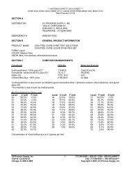
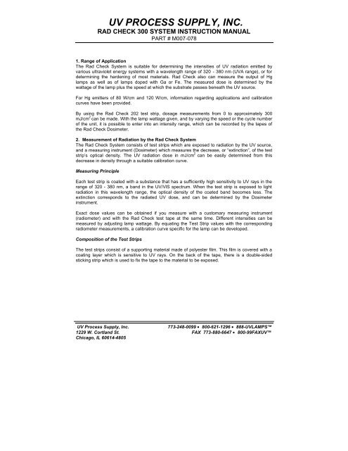
<strong>UV</strong> PROCESS SUPPLY, INC.RAD CHECK <strong>300</strong> SYSTEM INSTRUCTION MANUALPART # M007-0781. Range of ApplicationThe <strong>Rad</strong> <strong>Check</strong> System is suitable for determining the intensities of <strong>UV</strong> radiation emitted byvarious ultraviolet energy systems with a wavelength range of 320 - 380 nm (<strong>UV</strong>A range), or fordetermining the hardening of most materials. <strong>Rad</strong> <strong>Check</strong> also can measure the output of Hglamps as well as of lamps doped with Ga or Fe. The measured dose is determined by thewattage of the lamp plus the speed at which the substrate passes beneath the <strong>UV</strong> source.For Hg emitters of 80 W/cm and 120 W/cm, information regarding applications and calibrationcurves have been provided.By using the <strong>Rad</strong> <strong>Check</strong> 202 test strip, dosage measurements from 0 to approximately <strong>300</strong>mJ/cm 2 can be made. With the lamp wattage given, and by varying the speed or the cycle numberof the unit, it is possible to enter into an intensity range, which can be recorded by the tapes ofthe <strong>Rad</strong> <strong>Check</strong> Dosimeter.2. Measurement of <strong>Rad</strong>iation by the <strong>Rad</strong> <strong>Check</strong> SystemThe <strong>Rad</strong> <strong>Check</strong> System consists of test strips which are exposed to radiation by the <strong>UV</strong> source,and a measuring instrument (Dosimeter) which measures the decrease, or “extinction”, of the teststrip’s optical density. The <strong>UV</strong> radiation dose in mJ/cm 2 can be easily determined from thisdecrease in density through a suitable calibration curve.Measuring PrincipleEach test strip is coated with a substance that has a sufficiently high sensitivity to <strong>UV</strong> rays in therange of 320 - 380 nm, a band in the <strong>UV</strong>/VlS spectrum. When the test strip is exposed to lightradiation in this wavelength range, the optical density of the coated band becomes less. Theextinction corresponds to the radiated <strong>UV</strong> dose, and can be determined by the Dosimeterinstrument.Exact dose values can be obtained if you measure with a customary measuring instrument(radiometer) and with the <strong>Rad</strong> <strong>Check</strong> test tape at the same time. Different intensities can bemeasured by adjusting lamp wattage. By equating the Test Strip values with the correspondingradiometer measurements, a calibration curve specific for the lamp can be developed.Composition of the Test StripsThe test strips consist of a supporting material made of polyester film. This film is covered with acoating layer which is sensitive to <strong>UV</strong> rays. On the back of the tape, there is a double-sidedsticking strip which is used to fix the tape to the material to be exposed.<strong>UV</strong> <strong>Process</strong> <strong>Supply</strong>, Inc.773-248-0099 • 800-621-1296 • 888-<strong>UV</strong>LAMPS1229 W. Cortland St. FAX 773-880-6647 • 800-99FAX<strong>UV</strong>Chicago, IL 60614-4805
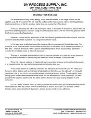
<strong>UV</strong> PROCESS SUPPLY, INC.RAD CHECK <strong>300</strong> SYSTEM INSTRUCTION MANUALPART # M007-078Handling and StorageAs the test strip coating is sensitive to <strong>UV</strong> rays, it can also be destroyed when exposed tosunlight. Therefore, it is necessary to protect the strip against ambient light at all times. The teststrip packing offers complete protection against exposure. Be sure to close the packing after eachuse. Also be sure to process the strips immediately after removal from the pack. <strong>Process</strong>ing atdiffused room light will not harm the strips, although you should avoid any direct exposure to thesun radiation and fluorescent lamps.In addition, the test strips have a certain thermal sensitiveness. Therefore, it is necessary to store<strong>Rad</strong> <strong>Check</strong> material in the refrigerator. Limited storage or transport at room temperature ispossible.Exposure of the Test StripAfter the test strip is removed from its pack, expose it to the <strong>UV</strong> source without delay. Using thestrip’s adhesive tab, attach the strip to the cylinder, belt or substrate that will be exposed to theradiation source.Please note that improper placement of the strip during the exposure sequence mayprovide inaccurate dosage readings.At high speeds, a second test sequence may be required to verify the initial reading results.Attach it in such a way that the subsequent measurement at the Dosimeter is not impaired.<strong>UV</strong> <strong>Process</strong> <strong>Supply</strong>, Inc.773-248-0099 • 800-621-1296 • 888-<strong>UV</strong>LAMPS1229 W. Cortland St. FAX 773-880-6647 • 800-99FAX<strong>UV</strong>Chicago, IL 60614-4805
<strong>UV</strong> PROCESS SUPPLY, INC.RAD CHECK <strong>300</strong> SYSTEM INSTRUCTION MANUALPART # M007-078After the tape has passed through the radiation source, the optical density, or extinction, shouldbe measured immediately.Measurement of <strong>UV</strong> IntensityStructure and Functioning of the Dosimeter Measuring Instrument (Brief Description)Measuring principle:Photometric transmitted-light measurement of test stripssensitive to <strong>UV</strong> radiationLight source:12v, 16 W commercial halogen lampSensor:<strong>UV</strong>-selective photodiode max. rel. sensitivity: 320 nm50% rel. sensitivity: <strong>300</strong> - 360 nmMeasuring transformer: Aluminum block to support the halogen lamp; photodiode,and guidance for measuring tape with end stop.Power: 110/220vView to the surface of Dosimeter<strong>UV</strong> <strong>Process</strong> <strong>Supply</strong>, Inc.773-248-0099 • 800-621-1296 • 888-<strong>UV</strong>LAMPS1229 W. Cortland St. FAX 773-880-6647 • 800-99FAX<strong>UV</strong>Chicago, IL 60614-4805
<strong>UV</strong> PROCESS SUPPLY, INC.RAD CHECK <strong>300</strong> SYSTEM INSTRUCTION MANUALPART # M007-078Execution of instrumentConnect the instrument to the 12v adapter. Switch “On” the instrument.DosimeterStartZero PointAccess announcementRequest for the calibration of the zero pointTo calibrate the zero point, slide a tape of uncoated supporting film - calibrating strip - into theSensor guide up to the end stop, and press CAL.The display reads:Zero PointPlease WaitDosimeterRead to MeasureCalibration of the zero point, (duration: 5 - 10 sec.)Flashing at the top right comerThe calibrated zero point remains stored.Afterwards, insert the test strip into the Sensor guide up to the end stop (the white point locatedby the inscription “<strong>UV</strong> Sensor” indicates the point of measurement).For this reason, do not write, stick or contaminate the tapes up to a length ofapproximately 30mm.Unlike when the strip is exposed, when the coated side must face the <strong>UV</strong> source, the test stripcan be measured whether the coated side faces up or down.Press the button OK = measurementMeasurementMeasurement, duration approx. 3 sec.Please WaitFlashing at the top right comerExtinction Measuring result (example: “1.62”)Several measurements can be carried out with the stored zero point. After approximately 10readings, or after receiving a non-linear reading, the zero point should be recalibrated.By building a calibration curve using the optical density value in conjunction with standardradiometric readings, you can determine <strong>UV</strong> intensity using the test strip and dosimeter.On the Dosimeter menu, several functions can be recalled or modified. To make a change, pressthe two arrow buttons. A called or modified menu option is always confirmed by pressing “OK".By pressing the button ON/OFF, the previous menu level is reached. The following options areavailable in the menu:1. Language: German or English.2. Battery: Measurement of the supply voltage with the switched “On” lamp.3. Date: Regulation of the actual date on the integrated real-time dock.4. Time: As under 3.5. K-factor (calibration): Allows you to correct for deviations in different test strip batches.<strong>UV</strong> <strong>Process</strong> <strong>Supply</strong>, Inc.773-248-0099 • 800-621-1296 • 888-<strong>UV</strong>LAMPS1229 W. Cortland St. FAX 773-880-6647 • 800-99FAX<strong>UV</strong>Chicago, IL 60614-4805
<strong>UV</strong> PROCESS SUPPLY, INC.RAD CHECK <strong>300</strong> SYSTEM INSTRUCTION MANUALPART # M007-0786. Autom. OFF Time for the automatic switch-off after the measurement hasbeen completed.7. System check <strong>Check</strong> of the electronic equipment.K factor (reader calibration):The K factor is numerical percentage value that allows the operator to accommodate for thedifferent density values that may occur between different batches of test strips. By adjusting thisvalue, the operator can establish a standardized baseline value for subsequent batches of teststrips regardless of their density values. This allows the operator to obtain comparablemeasurements from different batches of test strips even though their density values may differ.How to use the K Factor to calibrate different batches of Test Strips1. When you receive your first batch of test strips, follow the instructions for reading a teststrip provided above. Place an unexposed test strip into the reader and take a reading.This reading will provide you with the baseline value of the batch of test strips (batchnumber marked on the outside of each strip package). As there may be slight variationsfrom strip to strip (approximately 2%), repeat this procedure for three strips from thesame batch to obtain your baseline value. When measuring using this test strips batch,do not adjust the K factor. This becomes the instrument’s baseline value.2. When you receive subsequent batches of test strips, take readings of three unexposedstrips from the new batch. If there is no variation between readings of the unexposedstrips from the first batch to the next, do not change the K factor. If there is a variation,divide the initial baseline reading by the new batch reading. This will provide you with apercentage value that indicates the difference in density values between the two batchesof strips. Enter this value as your new K factor.ExampleThe three unexposed test strips measured from the first batch produced an average reading of1.60. The K factor was maintained at “1.00”. When a second batch of test strips was purchased,three unexposed test strips were measured and produced a reading of 1.73. By dividing 1.60 by1.73, a percentage value of .925 is obtained. This value is the difference between the twobatches. Adjust the K factor to 0.925. With this new K factor, the new batch of strips will producerecalibrated density baseline of 1.62. This corresponds to the initial batch and will hold thesubsequent values within acceptable error limits.IMPORTANT: THE BASELINE OBTAINED FROM THE FIRST BATCH OF TEST STRIPS ISTHE STANDARDIZED BASELINE FOR ALL SUBSEQUENT BATCHES. DO NOT LOSE THISVALUE. ALL TEST STRIPS MUST BE CALIBRATED TO THIS VALUE.3. Reproducibility and Measuring AccuracyWhen establishing System repeatability, we determined mean values, double standard deviation,and error percentage. The error percentage is approximately 2% for test strips not exposed toradiation. This increases slightly following exposure, and varies slightly depending on dosestrength.To obtain a reliable result, perform at least three measuring sequences for each determination.This method minimizes possible deviations, and permits clear determination of the correct value.Direct comparison between exposed and non-exposed test strips is favorable for a more accurateevaluation of radiation tests.Exposed and non-exposed tapes are measured one after the other, and the quotient ElE 0 is<strong>UV</strong> <strong>Process</strong> <strong>Supply</strong>, Inc.773-248-0099 • 800-621-1296 • 888-<strong>UV</strong>LAMPS1229 W. Cortland St. FAX 773-880-6647 • 800-99FAX<strong>UV</strong>Chicago, IL 60614-4805
<strong>UV</strong> PROCESS SUPPLY, INC.RAD CHECK <strong>300</strong> SYSTEM INSTRUCTION MANUALPART # M007-078formed. This method recognizes and minimizes errors relating to layer thickness. The calibrationcurves (provided with each test strip batch) indicate the dependence of the extinction E as well asthe dependence of the quotient E/Eo.Test Strip Specifications:• Dose Levels: Test Strip 01: 0-<strong>300</strong> mJ/cm2;• Range: 320-380nm• Durability: Approx. 6 months• Storage: Store in dark, cool environment, preferably refrigerated at 4-10°C• Packaging: Quantities of 100Dosimeter Specifications:• Light source: 12V/6w commercial halogen lamp• Sensor: <strong>UV</strong>-selective photodiode; max. rel. sensitivity: 320nm;50% rel. sensitivity: <strong>300</strong>-360nmTROUBLESHOOTINGLCD Message Problem Solution0.00 – CAL requested Pressed OK button without Calibrate.any calibration.0.00 – CAL canceled Pressed button other than CAL Repeat calibrationto stop calibration (the saved sequence.zero point is deleted.)0.00 – CAL error Density of calibration strip is too Repeat calibration withhigh (the saved zero point isa different calibrationdeleted).strip.0.00 – CAL error <strong>UV</strong> sensor is not working properly. Perform System <strong>Check</strong>.Problem may requiresensor replacement.Measure error Optical density of the measured Repeat calibration, then0.00 – CAL test strip is lower than the density repeat measure.of the calibration strip.Error! Low density! Optical density of the measured Test strip exposure (ortest strip is too low. Range of the Irradiation) is too strong.Strip not usable. sensing instrument has been If possible, reduce theexceeded.power of the radiationunit or process thestrip at a higherspeed. If not, contact<strong>UV</strong> <strong>Process</strong> <strong>Supply</strong>.<strong>UV</strong> <strong>Process</strong> <strong>Supply</strong>, Inc.773-248-0099 • 800-621-1296 • 888-<strong>UV</strong>LAMPS1229 W. Cortland St. FAX 773-880-6647 • 800-99FAX<strong>UV</strong>Chicago, IL 60614-4805
<strong>UV</strong> PROCESS SUPPLY, INC.RAD CHECK <strong>300</strong> SYSTEM INSTRUCTION MANUALPART # M007-078RAD CHECK DOSIMETETER CORRELATIONThe <strong>Rad</strong> <strong>Check</strong> system provides accurate and repeatable measurements of <strong>UV</strong> and EB dosagesby producing linear results, as shown above. The <strong>UV</strong> results above were made by passing a <strong>Rad</strong><strong>Check</strong> test strip beneath a <strong>UV</strong> source at an average dose rate of 71 mJ/cm 2 .The linear relationship exhibited between trials 1 and 6 shows that a simple formula can be usedto convert <strong>Rad</strong> <strong>Check</strong> dosimeter values to <strong>UV</strong> dose in mJ/cm 2 . The linear nature of the test stripshold for doses up to approximately 350 mJ/cm 2 .For best results, the <strong>Rad</strong> <strong>Check</strong> data should be correlated with radiometer readings at the facilitywhere it will be used. U V <strong>Process</strong> <strong>Supply</strong>, inc. provides this data as a demonstration of theeffectiveness of the <strong>Rad</strong> <strong>Check</strong> system.<strong>UV</strong> <strong>Process</strong> <strong>Supply</strong>, Inc.773-248-0099 • 800-621-1296 • 888-<strong>UV</strong>LAMPS1229 W. Cortland St. FAX 773-880-6647 • 800-99FAX<strong>UV</strong>Chicago, IL 60614-4805
<strong>UV</strong> PROCESS SUPPLY, INC.RAD CHECK <strong>300</strong> SYSTEM INSTRUCTION MANUALPART # M007-078This document provides information about a product distributed by<strong>UV</strong> <strong>Process</strong> <strong>Supply</strong>, Inc ("the Seller"). The information provided in this documentis offered in good faith and is believed to be reliable, but is madeWITHOUT WARRANTY, EXPRESS OR IMPLIED, AS TO MERCHANTABILITY,FITNESS FOR A PARTICULAR PURPOSE, OR ANY OTHER MATTER.This document is not intended to provide advice (technical, legal or otherwise)for a particular set of facts, but is of a general nature. Users of this documentshould consult with their own advisors and appropriate sources. The Seller and itsemployees do not assume any responsibility for the user's compliance with anyapplicable instructions, laws or regulations, nor for any persons relying on theinformation contained in this document.All risk arising out of the performance of this product and/or the understanding of itsusage remains solely with the Buyer. In no event shall the Seller be held liable forlost profits, lost savings, incidental or direct damages or other economic consequentialdamages regardless of any statement, expressed or implied, of such liability by theSeller's employees or any of its authorized agents. In addition, the Seller andits suppliers will be held harmless for any damages claimed on behalf of any third party.The Buyer of this product accepts full responsibility and understanding for theterms and specifications set forth herein.<strong>UV</strong> <strong>Process</strong> <strong>Supply</strong>, Inc.773-248-0099 • 800-621-1296 • 888-<strong>UV</strong>LAMPS1229 W. Cortland St. FAX 773-880-6647 • 800-99FAX<strong>UV</strong>Chicago, IL 60614-4805