EPR – Areva brochure
EPR – Areva brochure
EPR – Areva brochure
Create successful ePaper yourself
Turn your PDF publications into a flip-book with our unique Google optimized e-Paper software.
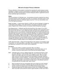
■ <strong>EPR</strong> NUCLEAR ISLANDSYSTEMSCHEMICAL AND VOLUME CONTROLThe Chemical and Volume Control System (CVCS) performs severaloperational functions.• Continuous controls the water inventory of the Reactor CoolantSystem (RCS) during all normal plant operating conditions, usingthe charging and letdown flow.• Adjusts the RCS Boron concentration as required for control ofpower variations and for plant start-up or shutdown, or tocompensate for core burnup, using demineralized water andborated water.• Ensures permanent monitoring of the Boron concentration of allfluids injected into the RCS, control of the concentration and thenature of dissolved gases in the RCS by providing the means ofinjecting the required Hydrogen content into the charging flow andallowing degassing of the letdown flow.• Enables the adjustment of the RCS water chemical characteristicsby allowing injection of chemical conditioning agents into thecharging flow.•Ensures a high flow rate capability for primary coolant chemicalcontrol with coolant purification, treatment, degassing and storage.•Injects cooled, purified water into the Reactor Coolant Pump (RCP)seals system to ensure cooling and leaktightness and collection ofthe seal leakage flow.• Supplies borated water to the RCS up to the concentrationrequired for a cold shutdown condition and for any initial condition.•Allows a reduction in pressure by condensing steam in thepressurizer by diverting the charging flow to the auxiliary pressurizerspray nozzle in order to reach Residual Heat Removal System(SIS/RHRS) operating conditions.• Allows filling and draining of the RCS during shutdown.• Provides a pressurizer auxiliary spray, if the normal system cannotperform its function, and make-up of the RCS in the event of lossof inventory due to a small leak.• Ensures the feed and bleed function.SAFETY INJECTION /RESIDUAL HEAT REMOVALThe Safety Injection System (SIS/RHRS) comprises the Medium HeadSafety Injection System, the Accumulators, the Low Head SafetyInjection System and the In-Containment Refueling Water StorageTank. The system performs a dual function both during the normaloperating conditions in RHR mode and in the event of an accident.The system consists of four separate and independent trains, eachproviding the capability for injection into the RCS by an Accumulator,a Medium Head Safety Injection (MHSI) pump and a Low HeadSafety Injection (LHSI) pump, with a heat exchanger at the pumpoutlet.During normal operating conditions, the system in RHR mode:• provides the capability for heat transfer from the RCS to theComponent Cooling Water System (CCWS) when heat transfervia the Steam Generators (SG) is no longer sufficiently effective(at an RCS temperature of less than 120 °C in normal operation),• transfers heat continuously from the RCS or the reactor refuelingpool to the CCWS during cold shutdown and refueling shutdown,as long as any fuel assemblies remain inside the containment.In the event of an assumed accident and in conjunction with theCCWS and the Essential Service Water System (ESWS), the SISin RHR mode maintains the RCS core outlet and hot legtemperatures below 180 °C following a reactor shutdown.The four redundant and independent SIS/RHRS trains are arrangedin separate divisions in the Safeguard Buildings. Each train isconnected to one dedicated RCS loop and is designed to providethe necessary injection capability required to mitigate accidentconditions. This configuration greatly simplifies the system design.The design also makes it possible to have extended periods availablefor carrying out preventive maintenance or repairs. For example,preventive maintenance can be carried out on one complete safetytrain during power operation.Chemical and Volume Control SystemSI/RHR SystemLOOP 1LOOP 4RegenerativeLetdown heat exchangerAuxiliary sprayPRTLOOP 2ReactorvesselLOOP 3Charging lineCCWSMHPcoolersMCCWSMSeal injectionLow pressurereducingSamplingsystemCoolantpurificationCoolantdegasification<strong>–</strong> Four train SIS<strong>–</strong> In-containment refuelingwater storage tank<strong>–</strong> Combined RHRS/LHSILHSI RHRpumpLHSI RHRpumpAccumulatorsHot legsAccumulatorsLHSI RHRpumpRHRSILHSI RHRpumpIRWSTIRWSTGastreatmentGas wasteprocessing systemVolumecontroltankCoolantstorageBoric acidmake-upWatermake-upMHSIpumpMHSIpumpIRWSTCold legsIRWSTMHSIpumpDivision 1 Division 2Division 3 Division 4MHSIpump34 IN2H2I 35


