EPR – Areva brochure
EPR – Areva brochure
EPR – Areva brochure

Create successful ePaper yourself
Turn your PDF publications into a flip-book with our unique Google optimized e-Paper software.
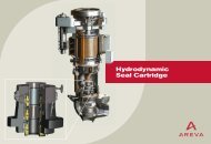
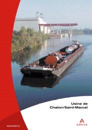
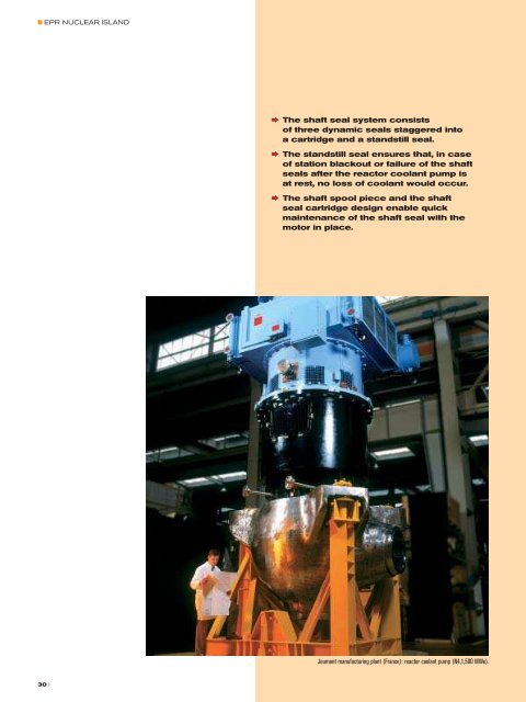
■ <strong>EPR</strong> NUCLEAR ISLAND† The shaft seal system consistsof three dynamic seals staggered intoa cartridge and a standstill seal.† The standstill seal ensures that, in caseof station blackout or failure of the shaftseals after the reactor coolant pump isat rest, no loss of coolant would occur.† The shaft spool piece and the shaftseal cartridge design enable quickmaintenance of the shaft seal with themotor in place.Chalon manufacturing plant (France): machining of primary piping elbow.CHARACTERISTICSDATAMain coolant linesPrimary loopsInside diameter of straight portions780 mmThickness of straight portions76 mmMaterial Z2 CN 19<strong>–</strong>10Surge lineInside diameter325.5 mmThickness40.5 mmMaterials Z2 CN 19<strong>–</strong>10(low carbon austenitic stainless steel)Jeumont manufacturing plant (France): reactor coolant pump (N4,1,500 MWe).Main Coolant LinesThe piping of the four primary loops and the pressurizer surgeline are part of the Reactor Coolant System installed in thereactor building. The reactor main coolant lines convey thereactor coolant from the reactor pressure vessel to the steamgenerators and then to the reactor coolant pumps, whichdischarge it back to the reactor pressure vessel.The surge line connects one of the four primary loops with thepressurizer.Each of the four reactor coolant loops comprises:<strong>–</strong>a hot leg, from the reactor pressure vessel to a steam generator,<strong>–</strong>a cross-over leg, from the steam generator to a reactor coolantpump,<strong>–</strong>a cold leg, from the reactor coolant pump to the reactor pressurevessel.A large inner diameter of 780 mm was chosen for all the legs tominimize the pressure drop and to reduce the coolant flow velocity inthe coolant lines.The surge line routing has been designed to avoid thermal stratificationduring steady state operation.The main coolant line materials and manufacturing processes havebeen selected to yield a high quality product with high toughnessproperties, and to improve inspectability and significantly reduce thenumber of welds.As already experienced on N4 reactors at the Civaux site, the materialis a forged austenitic steel, which exhibits excellent resistance tothermal aging and permeability for ultrasonic testing. The hot leg isforged, with separate forged elbows. The cold leg is made using“one-piece technology” with an elbow machined out of the forging.The cross-over leg is made of three parts, mainly for erectionconvenience. The surge line also consists of several segments. Majoradvances concerning welding processes are implemented. Thehomogeneous circumferential welds are made using the orbitalnarrow gap TIG welding technology. The weld is made with anautomatic TIG machine, which enables a large reduction of thevolume of weld metal and an enhanced quality level. The bimetallicweld joining austenitic to ferritic parts (like reactor pressure vesselor steam generator nozzles) is made by direct automatic narrow gapwelding of Inconel 52.Several nozzles, branches and piping connections are mounted oneach leg for auxiliary and instrumentation lines. Large nozzles areintegral with the main coolant lines. They are machined out of theforging of the piping. Small nozzles are set on welded, except forthe nozzles of the Chemical and Volume Control System, which areintegral with the main coolant line to improve their resistance tothermal fatigue.These design improvements strongly contribute to the capability forthe main coolant lines to fulfill the Leak Before Break requirements.† The main coolant lines design andmaterial are based on the technologyalready implemented on N4 reactorat the Civaux site.† They are made of forged austeniticstainless steel parts (piping and elbows)with high mechanical strength, nosensitivity to thermal aging and are wellsuited to in-service ultrasonic inspection.† Large nozzles for connection to auxiliarylines are integral and machined out of theforged piping (same for the Chemical andVolume Control System nozzles to avoidthermal fatigue effects).† The main coolant lines design and materialprovide justification of the application ofthe Leak Before Break concept.30 II 31