VIDEO DOOR INTERCOM
VIDEO DOOR INTERCOM
VIDEO DOOR INTERCOM
- No tags were found...

Create successful ePaper yourself
Turn your PDF publications into a flip-book with our unique Google optimized e-Paper software.
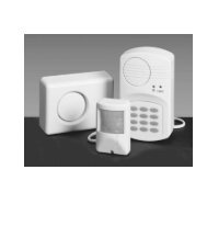
<strong>VIDEO</strong> <strong>DOOR</strong> <strong>INTERCOM</strong><strong>VIDEO</strong> <strong>DOOR</strong> ENTRY SYSTEM VT 623GB IEOperating and safety instructionsL76ContentsIntroduction ........................................................................Page 2Proper use .......................................................................... Page 2Package contents ................................................................ Page 2Equipment ...................................................................... Page 4Technical data .................................................................... Page 4Safety instructions ............................................................... Page 5Planning the installation ...................................................... Page 5Checking function ................................................................ Page 6Preparing wall mounting ..................................................... Page 6Connections ........................................................................ Page 6IntroductionRead through these operating instructions completely and carefully andwhile doing so fold out page 3 with the illustrations. The operatinginstructions are an integral part of the product and contain importantinformation about operation and handling. Always observe all thesafety instructions. If you have any questions or are unsure about usingthe equipment, ask a specialist, obtain internet information underwww.dexaplan.com or contact the service office. Keep these instructionsin a safe place and pass them on to third parties if necessary.Proper useThis video door entry system VT 623 consists of an outside stationVT 623C and an indoor station VT 623M which are connected using atwo -core connection cable. The maximum cable length is 75 m.The power supply is provided using the supplied mains adapter which isconnected to the indoor station. A chime (selectable) is heard at theindoor station when the doorbell button is pressed. After pressing abutton on the indoor station, two-way hands free conversation isenabled.When the doorbell button is pressed, the camera installed in the outdoorstation is activated automatically and the camera image is displayed onthe monitor of the indoor station. The camera can be activated forobservation by pressing a button on the indoor station: two-wayconversation can also be established thereafter.The camera image is displayed in colour. The infrared illuminationintegrated in the outdoor station is activated during darkness toilluminate the face of the person standing in front of the camera. Thisimage is displayed in black and white. The image quality in bad lightconditions will be improved by additional lighting.A powered speaker (not supplied) can be connected to the indoor stationFinishing the wall mounting ................................................. Page 7First use ............................................................................. Page 7Operation ........................................................................... Page 7Settings ............................................................................. Page 8Maintenance + cleaning .................................................... Page 8Disposal ............................................................................. Page 8Warranty ............................................................................ Page 8Service ...............................................................................Page 8Troubleshooting .................................................................. Page 9in order to amplify the chime and the conversation and/or relay it toanother place.An electric 12 V DC door release (not supplied) can be connected to theoutdoor station if desired. This can be activated at the indoor station bypressing a button. The system is intended for wall mounting wherebythe indoor station and the mains adapter are only approved for indooruse. A wedge shaped bracket is supplied for alignment of the outdoorstation. The system is only for private use and not for commercial use.Any other use or modification of the equipment is not authorised andpresents significant risks of accident. No liability will be accepted forconsequential damages or for damages caused by improper use orincorrect operation.Package contentsCheck the package contents are complete and that the equipment isundamaged immediately after unpacking.1x indoor station (incl. wall bracket)1x outdoor station (incl. wall bracket)1x two-core connection cable, approx. 15 m1x wedge shaped bracket for outdoor station1x mains adapter with approx. 2.5 m cable8x mounting screws8x wall plugs Ø 5 mm4x fixing screws for wedge shaped bracket3x fixing screws1x spare fuse1x spare nameplate1x operating and safety instructionsGB / IE - 2
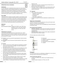
Troubleshooting1 2 3A BEquipmentPackage contents (see Fig. A):1 outdoor station2 indoor station3 wall bracket for indoor station4 fixing screws5 fixing screws for wedge shaped bracket6 spare fuse7 spare nameplate8 wall plugs for indoor station9 mounting screws for indoor station10 mounting screws for outdoor station11 wall plugs for outdoor station12 mains adapter13 low-voltage connector14 connection cable15 wedge shaped bracket for outdoor station16 wall bracket for outdoor stationOutdoor station front side (see Fig. B):17 infrared LEDs18 camera lens19 loudspeaker20 illuminated nameplate cover21 doorbell button22 microphoneOutdoor station rear side (see Fig. C):23 terminal cover24 grommet25 cable channel26 tabOutdoor station wall bracket (see Fig. D):27 hole for mounting screw28 cable opening (for laying along the wall)29 cable opening (for laying through the wall)30 hole for fixing screwWall bracket fixing for outdoor station on wedge shapedbracket (see Fig. E):31 hole for mounting screw32 cable openingIndoor station front side (see Fig. F):33 monitor34 loudspeaker35 operating status LED36 talk button37 door release button38 monitor button39 microphone40 reduce volume button41 increase volume button42 image adjustment buttonFaultNo image is displayed, the operating statusLED does not lightIndoor station side (see Fig. G):43 chime switch 1/2/344 chime volume switchNothing happens after pressing the doorbellbutton, “NO SIGNAL” is displayed on themonitor after pressing the Monitor buttonand the operating status LED lights red1615Indoor station wall bracket (see Fig. H):45 hole for mounting screw46 cable opening47 hole for fixing screw“NO SIGNAL” is displayed on the monitorafter pressing the Monitor button or thedoorbell button and the operating status LEDlights redC DNo image is displayed after pressing thedoorbell button, the LED display lights greenA whistling sound can be heardNo soundFConnection diagram (see Fig. I):48 optional powered loudspeaker (not supplied)49 keyhole slot50 connection for low-voltage current51 cable channel52 fuse holder53 terminal for powered loudspeaker54 + terminal for powered loudspeaker55 connecting cable terminal A56 connecting cable terminal B57 connection for optional electric door release58 connection for optional electric door release59 connecting cable terminal B60 connecting cable terminal A61 nameplate62 optional electric door release (not supplied)Technical dataThe image is displayed in black and whiteand maybe flickeringDark monitor image during twilight /darknessOutdoor station VT 623COperating voltage: from the indoor station (15 V DC)Power consumption: max. 1 AVoltage for door release : 12 V DC (max. 1 A) *Camera image sensor: 1/3“ CMOS colourCamera image resolution: 628 x 562 pixels (PAL)Camera lens: f = 4.5 mmCamera angle of view: approx. 64° horizontal, approx. 48° verticalThe image is also too dark during daylightI42414039Illumination: 9 infrared LEDs (for illumination of the closerange during darkness)The monitor image displays a brightbackground, however the visitor is displayeddark481413232425263334353637381210G1110984925076515261535455561575859604344451627282930E16155 10H93621718192021223132454647Twilight switch: activates infrared LEDs at approx. 2 LuxDimensions: approx.104 x 185 x 46 mm incl. wall bracketCasing material: PC, ABSWeight: approx. 333 g incl. wall bracketOperating temperature: -10 °C to +50 °CProtection class: IP 55* The door opener must meet these specifications+Indoor station VT 623MOperating voltage: 15 V DCPower consumption: max. 1.5 ACauseThe power supply is interruptedThe fuse has blownThe polarity of the connection between the outdoorstation and the indoor station is not correctThe connection between the outdoor station andthe indoor station has been interruptedThe cable is too long or its cross section is too smallThe settings cause a “black” imageIt is produced by acoustic feedbackThe volume on the indoor station has been set toolowThe power supply is interruptedThe connection between the outdoor station andthe indoor station has been interruptedThe polarity of the connection between the outdoorstation and the indoor station is not correctThe video signal is not switched correctlyThe wrong video system has been setThe outdoor station needs additional light in orderto be able to display a good imageYour viewing angle to the monitor is unfavourableThere is too much backlighting in the backgroundRemedyCheck the power supplyRemove the fuse holder [52] from the rear side of theindoor station and replace the fuse with an equivalentone (1 spare fuse is supplied)Correct the polarity of the connectionCheck the connection and polarityUse a suitable cable (wire cross section at least 0.75mm², max. length 75 m)Change the settings in the settings menuPlace the indoor and the outdoor stations further apartfrom each otherReduce the volume on the indoor stationRegulate the volume on the indoor stationCheck the power supplyCheck the connection and polarityCorrect the polarity of the connectionSwitch the monitor on and off using the Monitor button[38]Set the system to PALArrange additional lightingChange the mounting height of the indoor station oradjust the monitor brightnessInstall additional lighting or change the installationlocation of the outdoor stationGB / IE - 3 GB / IE - 4 GB / IE - 9
Fuse:250 V, 3 A; slow actionChime: max. 68 dB(A) (at distance of 1 m)Monitor:2.5” TFT, colourMonitor resolution: 640 x 240 pixelsLine-out output: 1 Vpp/ 600 OhmDimensions:approx. 100 x 180 x 34 mm incl. wall bracketCasing material: indoor station: PC, ABS;Wall bracket: AluminiumWeight:approx. 306 g incl. wall bracketRelative humidity: 20 - 80 %Operating temperature: -10 °C to +50 °CApplication:indoor use onlyMains adapterModel:KSAFF1500150W1Power supply: 100-240 V , 50/60 Hz, 0.6 APower output: 15 V , 1.5 AApplication:indoor use onlyConnection cableWire cross section:Supplied length:Max. length:Safety instructions2 x 0.75 mm²15 m75 m (min. 0.75 mm², copper)The following instructions are provided for your safety and satisfactionduring operation of the device. Note that non-observance of these safetyinstructions results in significant risks of accident.Explanation of symbols and terms used:Danger! If this point is not heeded life and health is endangered.Attention! Non-observance of these instructions puts property at riskof damage.Tip: Optimum results will be achieved by observing these instructions.Danger!Do not leave small children unsupervised with the device, packagingmaterial or small parts. Otherwise there is a risk of fatal injury due tochoking or suffocation.Perform the connection and installation while the mains power isdisconnected! Otherwise there is a risk of fatal injury due to electricshock.Do not damage any gas, electricity, water or telecommunication linesduring drilling and fixing work. Otherwise there are dangers ofpersonal and fatal injury and fire.Treat the cables carefully. Lay these so that they cannot be damagedand do not present any tripping hazard. Fix the cables sufficiently. Donot pull the cables over sharp edges and do not crush or crimp themelsewhere. Otherwise there are dangers of personal and fatal injuryand fire.Do not place the equipment near fire, heat or long lasting hightemperature effects of more than +50 °C. Otherwise there is a risk offatal injury due to fire.Do not connect any external voltage to the connection terminals.Otherwise there are dangers of personal and fatal injury and fire.Plug the mains adapter for the mains power connection into the mainssocket completely. Do not touch it with wet hands. Otherwise there is arisk of fatal injury due to electric shock.Only operate the indoor station and the mains adapter in dry areas.Do not expose them to dripping or splash water. Only clean theequipment with a dry and, if necessary slightly moist, cloth. Do notsubmerge the equipment in water. Otherwise there is a risk of fatalinjury due to electric shock and fire.Do not connect any damaged device (e.g. transport damage) anddisconnect the power supply immediately in the case of damage.Unplug the mains adapter from the mains socket. Arrange for thedamage to be repaired immediately by a specialist. Otherwise there isa risk of fatal injury due to electric shock.Attention!Only operate the system with 15 V DC from the supplied powersupply. Before connecting the power supply to the mains, ensure thatthe mains current complies with 230 V AC, 50 Hz and is fitted witha fuse according to local regulations.Protect the equipment and the cables against strong magnetic orelectrical fields and against strong mechanical loads and vibrations.Only have repairs carried out by authorised and trained qualifiedpersonnel. Otherwise there is a risk of damage due to improper useand invalidation of the warranty.Planning the installationObserve the following points:Outdoor station: Protect the outdoor station as much as possible against direct rainfall. Mount the outdoor station at such a height that visitors cancomfortably reach the doorbell button and that the face of the personringing the bell is in the field of view of the camera. Pay attention tothe height of children in doing so. The vertical detection angle of thecamera is approx. 48°. The outdoor station is usually installed at the side of the entrancedoor. Ensure that the face of the visitor standing in front of the doorcan be seen on the screen. The horizontal detection angle of thecamera is approx. 64°. If necessary, use the enclosed wedge shapedbracket to align the outdoor station. Position the outdoor station so that no direct light falls on the lensopening. Avoid strong backlighting behind the visitor: in this case, theperson appears darker on the image. Check the camera image beforemounting. Put the unit into operation and hold the outdoor station inthe desired place for this. If necessary, change the position until youhave found the optimum image. Remember that the position of thesun changes. Suitable cable routing must be available, also for the optional electricdoor opener.GB / IE - 5
Indoor station Mount the indoor station on the wall at a suitable central place insidethe residence, e.g. in the hall. Ensure that the chime can be heardeverywhere inside the residence. If the chime is not sufficiently audible, an additional poweredloudspeaker can be connected. Arrange the indoor station at face height so that you can observe themonitor and can communicate using the hands-free system. Directlyopposite or slightly down onto the monitor are the best viewingdirections. Take account of the height of everybody living in theresidence including children when determining the mounting height. Ensure that there is a mains power socket for the mains power supplywithin the range of the mains adapter cable. Pay attention to the length of the necessary connection cable to theoutdoor station. The maximum length is 75 m. A suitable existing2cable can be used if available (wire cross section min. 0.75 mm , max.length 75 m). One 15 m cable is supplied. Avoid laying theconnection cable directly next to other electrical cables as thisadversely affects the image and sound quality.Checking functionUnpack the equipment and remove all plastic protective packaging.Provisionally lay the connection cable [14] from the intendedinstallation location of the indoor station to the intended installationlocation of the outdoor station.Using the connection cable, connect the outdoor station [1] to theindoor station [2] according to the connection diagram (see Fig. I).If desired, connect an optional door opener [62] (not included in thepackage contents) with a two-core cable (not included) to the outdoorstation according to the connection diagram (see Fig. I).Connect the low-voltage connector [13] to the connection [50].Plug the mains adapter [12] into a mains power socket.Check the function (see Chapter “Operation”).Check the image detail.Optimise the placement of the equipment.Unplug the mains adapter from the mains socket.Disconnect all other connections.Now continue with the wall mounting.Preparing the wall mountingLay the cable between the indoor and the outdoor stations:along the wall Run the connecting cable [14] and if required a two-core cable foran optional door opener along the wall (laid on the surface or inwall slits).Through the wall Drill a corresponding cable opening hole (Ø at least 8 mm)directly behind the cable opening [29 and 46] of the wall bracketof the outdoor and indoor station or behind the cable opening[32] of the wedge shaped bracket if necessary.Put the connection cable and if applicable the two-core cable foran optional door opener through the cable opening hole. In doingso, plan a sufficient cable length for the connection to thestations.Outdoor station / Indoor station: Mounting with wallbracket (see Fig. D and H) Hold the wall bracket [3 and 16] at the desired mounting point andmark the four drill holes on the wall with a pencil. Pay attention whenlaying the cable through the wall that the cable opening [29 and 46]is aligned with the cable. Drill the 4 holes (Ø 5 mm). When laying the cable through the wall, guide the cable through thecable opening of the corresponding wall bracket. Fix the wall bracket in place to the wall using the four mountingscrews [9 and 10] and four wall plugs [8 and 11].Outdoor station: Mounting with wall bracket and wedgeshaped bracket (see Fig. E)The wedge shaped bracket changes the horizontal alignment of theoutdoor station by 30°. You can mount it on the left or right side of thedoor by turning it upside down.Hold the wedge shaped bracket [15] at the desired mounting pointand mark the four drill holes on the wall with a pencil.Drill the 4 holes (Ø 5 mm).When laying the cable through the wall, guide the cable through thecable openings of the wall bracket and the wedge shaped bracket[29/32].Fix the wedge shaped bracket in place to the wall using the fourmounting screws [10] and wall plugs [11].Fix the wall bracket [16] to the wedge shaped bracket using the fourfixing screws [5].Indoor station: Hanging on the wall without wall bracketThe indoor station can also be hung on the keyhole slots [49]. Drill two holes at the desired mounting position (Ø 5 mm) withhorizontal spacing of 4.6 cm. Insert two wall plugs [8] in the drilled holes. Screw the two mounting screws [9] into the drilled holes so that thescrew heads protrude approx. 5 mm from the holes.ConnectionsConnecting the outdoor station to the indoor station Remove the four screws of the outdoor station terminal cover [23]. Lift the terminal cover at the tab [26]. Label the nameplate: Remove the nameplate [61] completely from the slot. Label the nameplate. In doing so, note that only 4 cm are visible. Slide it back into the slot as far as the stop. Carefully make a hole using a pointed object in one of theGB / IE - 6
predetermined breaking points of the grommet [24].Guide the connection cable [14] through this hole.If required, make a second hole for the cable of an optional dooropener and guide the cable through this hole.Connect the connection cable [14] to the terminals of the outdoorstation [59, 60] and the indoor station [55, 56] according to theconnection diagram (see Fig. I). Pay attention here to the wiremarkings and the polarity (A to A, B to B).If desired, connect an optional door opener [62] (see next chapter).Replace and screw down the terminal cover on the outdoor station.Connecting an optional door opener If desired, install an optional door opener [62] (not included in thepackage contents) at the desired location according to the instructionsof the manufacturer. Connect it to the terminals [57] and [58] of the outdoor station with atwo-core cable (polarity-independent) according to the connectiondiagram (see Fig. I).Connecting optional powered loudspeaker Connect an optional powered loudspeaker [48] (not included in thepackage contents), e.g. a PC speaker, to the terminals [53] and [54]of the indoor station with a two-core cable according to the connectiondiagram (see Fig. I). Pay attention to the polarity for the connection.Connecting the mains adapter to the indoor station Connect the low-voltage connector [13] to the connection [50].Finishing the wall mountingFinishing the outdoor station mounting For cable routing along the wall: Guide all connected cables throughthe cable opening [25]. Slide the outdoor station [1] at an angle upwards into the wall bracketand push it into place. Fix the outdoor station to the wall bracket through the two holes [30]with two of the fixing screws [4].Finishing the indoor station mountingScrewing to the wall For cable routing through the wall: Place the connection cable [14]into the cable channel [51]. For cable routing along the wall: Place the mains adapter cable intothe cable channel [51]. Slide the indoor station [2] at an angle upwards into the wall bracketand push it into place. Fix the indoor station to the wall bracket through the hole [47] withone fixing screw [4].Hanging on the wall Hang the indoor station [2] on the two protruding screw heads in thewall using the keyhole slots [49].First use Plug the mains adapter [12] into a mains power socket. The operatingstatus LED [35] lights green and the nameplate cover [20] isilluminated from the back. Remove the protective film from the monitor [33].The video door entry system is now ready for operation.OperationA visitor presses the doorbell button [21] of the outdoor station. A chimesounds from the indoor station. The camera image is displayed on themonitor [33] and the operating status LED [35] lights red. It can now beheard on the indoor station what is said at the outdoor station.If the visitor presses the doorbell button again, the chime sounds again. Press the talk button [36] to speak to the visitor. The LED of thetalk button flashes blue. Now speak into the microphone [39]. The visitor hears you by meansof the loudspeaker [19] of the outdoor station and can talk to youusing the microphone [22] of the outdoor station. You hear the visitorby means of the loudspeaker [34] of the indoor station. Press the talk button again to end the conversation; otherwisethe connection will end automatically after 4 minutes. The LED of thetalk button stops flashing and the monitor image disappears.If you do not react to the visitor pressing the doorbell button, the monitorimage disappears after approx. 60 secondsNote:You can only start the talk function when the monitor image is activated.The chime and the conversation are relayed to a powered loudspeaker ifconnected. If the powered loudspeaker has a volume control, you canadjust the volume independently of the indoor station volume.Door opener (optional)If a door opener is connected, you can unlock the door / gate as followsLatching door openerWith a latching door opener the door or gate remains open after the signal. Press the door opener button [37]. The gate or the door is lockedagain after it has been opened and closed again.Non-latching door opener Keep the door opener button [37] pressed until the visitor hasopened the door. The door remains unlocked for the period in whichyou keep the button pressed. Release the door opener button and the door opener locksimmediately.While the door opener button is pressed, the LED of the door opener buttonflashes blue for approx. 2 seconds, the monitor image disappears for ashort time, “NO SIGNAL” is displayed briefly on the monitor and thenameplate is not illuminated.Note:Unlocking the door / gate is only possible when the monitor image isactivated.GB / IE - 7
Switching the monitor on and off Press the monitor button [38] in order to see the camera image.The camera image is displayed on the monitor and the operatingstatus LED [35] lights red. The monitor image disappears when the monitor button is pressedagain or automatically after approx. 60 seconds and the operatingstatus LED lights green again.SettingsAdjusting the monitor imageThe adjustments can only be made when the monitor image is activated Press the monitor button [38]. Press the image adjustment button [42] once; the settings menuis displayed on the monitor. You reach the respective next menu item by repeated pressing of theimage adjustment button (the current menu item is pink) or thesettings menu disappears after the last menu item. The correspondingsetting value is displayed numerically and graphically as a bar. You can change the setting value of the respective menu item bypressing the buttons + [41] and [40].BRIGHTNESS: Brightness (0 to 100)CONTRAST: Contrast (0 to 100)SHARPNESS: Sharpness (0 to 6)COLOUR: Colour saturation (0 to 100)HUE:Hue (0 to 100); not active for PAL setting<strong>VIDEO</strong>: NTSC or PAL (set to PAL)The settings menu disappears automatically after approx.10 seconds if noaction is taken in the menu, however at the latest after approx. 60 secondswhen the monitor image disappears.Tip:In order to have sufficient time for the adjustment, press the talk button[36] after switching on the monitor as the monitor image thenremains switched on for approx. 4 minutes.Adjusting the volume of the indoor station ring toneIn 2 steps In order to have a quieter chime, set the volume switch [44] to“-“; set it to “+* for the louder chime.Continously adjustable Switch on the monitor using the monitor button [38]. Press the volume button + [41] to increase the volume of thechime and the conversation; to reduce the volume, press the volumebutton [40] (settings value will be displayed on the monitor:can be set between 0 and 100).Selecting chime melodyYou can select one of three melodies using the chime switch 1/2/3[43]. Set the chime switch to one of the three positions:Position 1:Position 2:Position 3:2x “Ding-Dong”short melodylonger melody “For Elise”Maintenance + cleaningThe unit is maintenance-free.Regularly check the technical safety and functioningUse a dry cloth for cleaning the surfaces. For stubborn dirt, clean thesurfaces with a soft, fluff-free, slightly moist cloth without cleaningadditives.Carefully clean the slits of the loudspeaker [19 and 34] with a drybrush.DisposalDo not simply throw away packaging material and worn-outequipment but send it for recycling. Please ask your local authorityfor details of your recycling centre or nearest collection point.WarrantyThis product is warranted for 3 years from the date of purchase. Keep thetill receipt in a safe place as proof of purchase. Contact the service office inyour country in the event of a warranty claim. This warranty is only validfor the original purchaser and cannot be transferred. The warranty onlycovers material or manufacturing defects. It does not cover wear ordamage to fragile parts. The product is only intended for private use andnot for commercial use. The warranty is void in the case of misuse and/orimproper handling, application of force and for any unauthorized repairs.This warranty does not affect your legal rights.ServiceInformation about dealing with problems is available atwww.dexaplan.com. Contact our service centre by email(service@dexaplan.de) or by telephone ( GB 0870 / 241 3029Mon Fri 08:30 17:00 / IE 1890 851 851 Mon Fri 08:30 17:00)for any questions. You can obtain all the necessary information aboutservice issues, such as returning a defective product etc.Dexaplan GmbHPaul-Böhringer-Str. 3D - 74229 Oedheim12/10/2007Ident-No.: 12-10-2007-VT 623-GB-L76GB / IE - 8