Download SOR Capacitance Level Switch ... - Proflow Systems
Download SOR Capacitance Level Switch ... - Proflow Systems
Download SOR Capacitance Level Switch ... - Proflow Systems
- No tags were found...

Create successful ePaper yourself
Turn your PDF publications into a flip-book with our unique Google optimized e-Paper software.
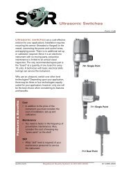
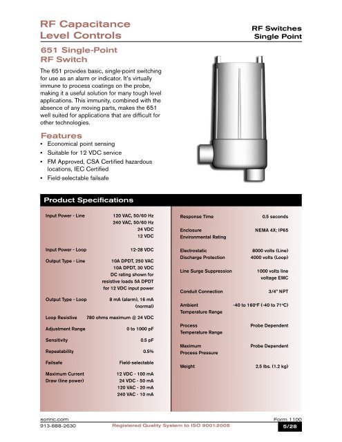
RF <strong>Capacitance</strong><strong>Level</strong> ControlsRF <strong>Switch</strong>esSingle Point651 Single-PointRF <strong>Switch</strong>The 651 provides basic, single-point switchingfor use as an alarm or indicator. It’s virtuallyimmune to process coatings on the probe,making it a useful solution for many tough levelapplications. This immunity, combined with theabsence of any moving parts, makes the 651well suited for applications that are difficult forother technologies.Features• Economical point sensing• Suitable for 12 VDC service• FM Approved, CSA Certified hazardouslocations, IEC Certified• Field-selectable failsafeProduct SpecificationsInput Power - Line120 VAC, 50/60 Hz240 VAC, 50/60 Hz24 VDC12 VDCResponse TimeEnclosureEnvironmental Rating0.5 secondsNEMA 4X; IP65Input Power - LoopOutput Type - LineOutput Type - LoopLoop ResistiveAdjustment RangeSensitivity12-28 VDC10A DPDT, 250 VAC10A DPDT, 30 VDCDC rating shown forresistive loads 5A DPDTfor 12 VDC input power8 mA (alarm), 16 mA(normal)780 ohms maximum @ 24 VDC0 to 1000 pF0.5 pFRepeatability 0.5%ElectrostaticDischarge ProtectionLine Surge SuppressionConduit Connection8000 volts (Line)4000 volts (Loop)1000 volts linevoltage EMC3/4” NPTAmbient -40 to 160 o F (-40 to 71 o C)Temperature RangeProcessTemperature RangeMaximumProcess PressureProbe DependentProbe DependentFailsafeField-selectableWeight2.5 lbs. (1.2 kg)Maximum Current12 VDC - 100 mADraw (line power)24 VDC - 50 mA120 VAC - 20 mA240 VAC - 10 mAsorinc.com913-888-2630Registered Quality System to ISO 9001:2008Form 11005/28
RF <strong>Capacitance</strong><strong>Level</strong> ControlsHow to OrderThe 651 consists of two parts. The first is the electronics and housing. The second is the probe. For probetypes and model numbers, see pages 21-25.Model Number System651 K-7-TTYY651 RF Admittance <strong>Switch</strong> with 120 VAC power supply, oversized nameplate and epoxy-coated housing.Power Supply112 VDC 524 VDC 6120 VAC 7240 VAC 812 - 28 VDC 9(Loop)2AlCSFlFMMBODOFPPPYRRAccessories & CertificatesCSA Intrinsically Safe*CSA Explosion Proof Listing*FM Intrinsically Safe*FM Explosion Proof Listing*IEC Certified Intrinsically Safe*60-second time delay ON, 0.5-second delay OFF60-second time delay OFF, 0.5-second delay ONFiber tag with customer-specified tag informationPowder Coat epoxy coating. No coating on stainless steelparts or plated screws. (500 hours-salt spray)SS wired on nameplate with customer-specified information* Electronics and probe musthave the same agency tomaintain the listing integrity(i.e. CS or AI electronicswith CS probe, or FM or FIelectronics with FM probe).Agency ApprovalTTVVYYC1C3C4C6SS nameplate permanently affixed to housing withcustomer-specified tag informationFungicidal varnish applied to housing exteriorEpoxy coating applied to housing exterior(200 hours-salt spray)Individual CertificatesCertificate of CalibrationInspectionCompliance/ConformanceInsulation Resistance651K 7 TT YY Model NumberAgency Safety Method Approval Model(s)FM Explosion Proof Class I, Groups C, D 651Kx-FMClass II, Groups E, F, GClass III, Division 1Intrinsically Safe Class I, Groups A, B, C, D 651Kx-FIClass II, Groups E, F, GClass III, Division 1CSA Explosion Proof Class I, Groups C, D 651Kx-CSClass II, Groups E, F, GClass III, Division 1Intrinsically Safe Class I, Groups A, B, C, D 651K9-AIClass II, Groups E, F, GClass III, Division 1IEC Intrinsically Safe Ex ia IIB T4 651K9-MBForm 11006/28 Registered Quality System to ISO 9001:2008sorinc.com913-888-2630
RF <strong>Capacitance</strong><strong>Level</strong> ControlsHow to OrderThe 681 consists of two parts. The first is the electronics and housing. The second is the probe. For probetypes and model numbers, see pages 21-25.Model Number System681 K-7-TTYYThe 681 RF Admittance <strong>Switch</strong> with 120 VAC power supply, oversized nameplate and epoxy-coatedhousing.Electrical HousingIntegral HousingRemote housing: 150 ft. (45m)maximumOrder remote cable part #2924-113and specify length in feet1KR2Power Supply5 12 VDC6 24 VDC7 120 VAC8 240 VAC9 10 to 30 VDC (Loop)3ADBKPKPPPYRRTTVVYYAccessories & CertificatesAdjustable differential(do not use DT accessory)Remote electronics flat-surface mountingbracket (R housing only)Pipe mounting kit - BK accessory required(R housing only)Fiber tag with customer-specifiedinformationPowder Coat epoxy coating. No coating on stainlesssteel parts or plated screws. (500 hours-salt spray)SS wired-on nameplate with customerinformationSS nameplate permanently affixed tohousing with customer-specified informationFungicidal varnish applied to housing exteriorEpoxy coating applied to housing exterior(200 hours-salt spray)Individual CertificatesC1 Certificate of CalibrationC3 InspectionC4 Compliance/ConformanceC6 Insulation Resistance681 K 7 TT YY Model NumberAgency ApprovalThere are no third-party approvals at this time.Form 11008/28 Registered Quality System to ISO 9001:2008sorinc.com913-888-2630
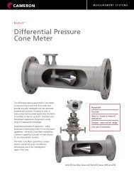
RF <strong>Capacitance</strong><strong>Level</strong> Controls660 Series Multi-PointRF <strong>Switch</strong>The 660 Series provides the options of multiplepointswitching plus narrow and wide differentialswitching. By combining these features, the660 Series units can be used for a wide varietyof control needs. The available switchingcombinations are designed to provide multiplealarms, pump/valve control, or a combination ofalarms and equipment control. The 660 Seriesmakes it possible to combine up to four singlepointdevices into one package for lower costsand reduced maintenance.Features• Up to 4-point indication• Suitable for 12 VDC service• FM Approved and CSA Certified forhazardous locations• Field-selectable failsafe• Resists process media coatingRF <strong>Switch</strong>esMulti-Point<strong>Switch</strong>ing CombinationsThe 660 Series has eight different combinationsof fixed differential and/or adjustable differentialswitching points. Each unit is equipped with oneof four discreet switching points. These points canbe used to provide true point level sensing withno level differential, or latched together to providewide, adjustable differential.See page 11 for available combinations. Requiredcombinations are selected using step 1 in theHow to Order chart on page 10.Product SpecificationsInput PowerOutput Type120 VAC, 50/60 Hz240 VAC, 50/60 Hz24 VDC, 12 VDC10A DPDT, 250 VAC10A DPDT, 30 VDCDC rating shown forresistive loadsEnclosureEnvironmental ProtectionElectrostaticDischarge ProtectionLine Surge SuppressionNEMA 4X; IP658000 volts1000 volts linevoltage EMCAdjustment Range0 to 2000 pFConduit Connection1” NPT(F)Sensitivity0.5 pFRepeatability 0.5%FailsafeField-selectableMaximum Remote 4000 feet (1219.2 m)Distance from SensorAmbient -40 to 160 o F (-40 to 71 o C)Temperature RangeMaximum CurrentDrawResponse Time12 VDC - 245 mA24 VDC - 123 mA120 VAC - 74 mA240 VAC - 36 mA0.5 second (standard)ProcessTemperature RangeMaximumProbe PressureProbe DependentProbe DependentTime Delay (optional)0 to 30 secondsWeightJ Housing: 9 lbs. (4.1 kg)R Housing: 11 lbs. (5 kg)W Housing: 6 lbs. (2.7 kg)sorinc.com913-888-2630Registered Quality System to ISO 9001:2008Form 11009/28
RF <strong>Capacitance</strong><strong>Level</strong> Controls663 RF Admittance 3-point switch with 12 VDC powersupply, time delay and fungicidal varnished housing.Electrical Housing 2How to OrderThe Series 660 is comprised of two parts. The first is the electronics and housing. The second is the probe.Refer to pages 21-25 for probe model number.Model Number SystemPower Supply66 3 J5-TDVV35 12 VDC6 24 VDC7 120 VAC8 240 VAC<strong>Switch</strong>ing CombinationSee page 11 for switching combinations.Integral housingExplosion-proof remote housing(4000 feet [1219.m] maximum)Weathertight remote housing(4000 feet [1219.2m] maximum)1Single fixed differential switching point 1Two fixed differential switching points 2Three fixed differential switching points 3Four fixed differential switching points 4Single adjustable differential switching 5.High-level fixed differential point and 6adjustable differential switchingSingle adjustable differential and low- 7level fixed differential point switchingHigh- and low-level fixed differential points 8and adjustable differential switchingJRW4 Accessories& CertificatesBKCSFMPKPPPYRRTDTTVVRemote electronics flatsurface mounting bracket(R housing only)CSA explosion-proof listing*FM explosion-proof listing*Pipe mounting kit- BK accessoryrequired (R housing only)Fiber tag with customerspecifiedinformationPowder Coat epoxy coating.No coating on stainless steel partsor plated screws.(500 hours-salt spray)SS wired-on nameplate withcustomer-specified informationTime delay for each fixeddifferential set pointSS nameplate permanentlyaffixed to housing withcustomer-specified informationFungicidal varnish applied tohousing exterior* Electronics and probe must have the sameagency to maintain the listing integrity (i.e.CS or AI electronics with CS probe, or FMor FI electronics with FM probe).YYC1C3C4C6Epoxy coating applied to housingexterior (200 hours-salt spray)Individual CertificatesCertificate of CalibrationInspectionCompliance/ConformanceInsulation ResistanceAgency Approval66 3 J 5 TD VV Model NumberAgency Safety Method Approval Model(s)FM Explosion Proof Class I, Groups B, C, D 66x-Jx-FMClass II, Groups E, F, G 66x-Jx-FMClass III, Division 1CSA Explosion Proof Class I, Groups C, D 66x-Jx-CSClass II, Groups E, F, G 66x-Rx-CSClass III, Division 1Form 110010/28 Registered Quality System to ISO 9001:2008sorinc.com913-888-2630
RF <strong>Capacitance</strong><strong>Level</strong> ControlsRF <strong>Switch</strong>esMulti-pointConnection CableRemote units require #22AWG shielded twisted pair cable to connect the control to the probe. The maximumlength of this cable is 4000 feet (1219.2m).A 25 ft. (7.6m) cable is supplied with each unit. Other lengths can be ordered per the information below. Thecable glands supplied with the unit must be replaced with suitable fittings when installing conduit.Specific length cablePart Number 2924-103 Specify length and units1000 ft. (305m) reel Part Number 2924-102 (reel is non-returnable)Order cable by the part numbers listed below.Series 660 <strong>Switch</strong>ing CombinationsFixedDifferentialFixedDifferentialFixedDifferentialFixedDifferentialFixedDifferentialFixedDifferentialFixedDifferentialFixedDifferentialFixedDifferentialFixedDifferentialFixedDifferentialFixedDifferentialFixedDifferentialFixedDifferentialsorinc.com913-888-2630Registered Quality System to ISO 9001:2008Form 110011/28