GRIT HAPPENS â YOU DON'T KNOW WHAT YOU ARE MISSING
GRIT HAPPENS â YOU DON'T KNOW WHAT YOU ARE MISSING
GRIT HAPPENS â YOU DON'T KNOW WHAT YOU ARE MISSING
- No tags were found...

You also want an ePaper? Increase the reach of your titles
YUMPU automatically turns print PDFs into web optimized ePapers that Google loves.
<strong>GRIT</strong> <strong>HAPPENS</strong> – <strong>YOU</strong> DON’T <strong>KNOW</strong> <strong>WHAT</strong> <strong>YOU</strong> <strong>ARE</strong> <strong>MISSING</strong>Pat Herrick, Hydro International Wastewater DivisionHydro International - Wastewater Division2925 NW Aloclek Drive, #140 - Hillsboro, OR 97124(503) 615-8130ABSTRACTOperator dissatisfaction with grit removal systems is all too common. Design of grit removal processeshas been labeled as inadequate and misunderstood. Conventional guidelines target removal of grit largerthan 210 µm while minimizing organic content. In fact, many wastewater treatment plants across thecountry find over 50% of their influent grit is smaller than 210 µm. In addition to designing for inadequateremoval based on size alone other factors contribute to grit system failure. Conventional design assumesthat municipal grit settles like clean sand particles in clean water. Grit removal systems are traditionallybased on settling velocities of perfect spheres of silica sand particles with a 2.65 specific gravity in cleanwater. In reality, wastewater grit is comprised of silica sand as well as asphalt, concrete and various othermaterials that do not have a specific gravity of 2.65. Further, grit particles are not all perfect spheres andfinally, grit is exposed to fats, oils, greases, and soaps in the collection system which coats the grit andchanges its settling velocity. Grit systems can work as intended when designed with an accurateunderstanding of the nature and characteristics of the grit arriving at the treatment plant and how this gritactually behaves in wastewater. Advancements in grit management technology now allow 95% captureof grit as fine as 75 µm while producing a clean, dry product.KEYWORDS: Grit Removal System, Size Distribution, Settling Velocity, Specific Gravity, Shape,Agglomeration, Sand Equivalent Size (SES)CONVENTIONAL DESIGNMeeting regulatory requirements for treated effluent quality is the major focus for wastewater treatmentfacilities. Grit removal, since it is not a regulated constituent, has historically been treated as anafterthought. Yet, wastewater treatment plants can be significantly and negatively impacted by grit.Traditional design guidelines target removal of coarse grit particles while minimizing organic content. Theconventional design criterion for grit removal systems, based on Metcalf & Eddy, WEF MOP #8, and othertrade manuals, has historically been to target grit particles 210 µm and larger, with a specific gravity of2.65. The results of these design criteria are more likely to produce a product with low organic content inorder to make it acceptable at a landfill than to eliminate the grit which passes through the removalsystem causing problems for the plant. Producing a low organic content grit is an important goal to keepin mind when designing a grit removal system, as organics create odor issues, as well as increasingvolume and water content which can increase vector attraction and make the product unacceptable at alandfill. However, the primary goal of any grit removal system should be to minimize the grit which iscausing abrasive wear on mechanical equipment and depositing in process basins throughout the plant.ABRASION & DEPOSITIONGrit is a nuisance material which causes abrasive wear to mechanical equipment and in turn increasesmaintenance and operational costs while reducing equipment performance and useful life. Equipmentsuch as primary sludge pumps, thickener feed pumps, sludge dewatering pumps, digester draft tubes andmixers, centrifuges, and process collectors and screws are especially susceptible.In addition to the abrasive effects, grit accumulates in processes throughout a plant reducing processingcapacity and detention time and influencing circulation patterns. Velocities through most process basinsare lower than design velocities in the collection system. If grit is not removed in the headworks, it willsettle once it arrives in a process basin which has lower velocities and a fine particle “deposit limit”. Finebubble aeration basins and digesters have a “deposit limit” of approximately 100 µm (Wilson,Tchobanoglous, Griffiths, 2007). If grit particles as small as 100 µm are not removed in the headworksGrit Happens – You Don’t Know What You Are Missing
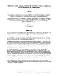
they will deposit throughout the process where conditions are conducive to settling, the grit thenconsumes tank volume and reduces process capacity.Processes such as fine bubble aeration basins, primary clarifiers and digesters are susceptible to gritdeposition. The reduction in processing capacity can affect the plant’s ability to achieve process designgoals such as; reducing methane production, reducing volatile solids reduction or impeding mixingeffectiveness in digesters (Massart, O’Kelley & Neun, 2010); or increasing operational costs, such ashorsepower requirements in aeration basins (Herrick, 2009).At most treatment plants, grit accumulations typically happen gradually and continuously. It often goesunnoticed until a process is completely overwhelmed and needs to be shut down to manually remove thedeposited grit, which is a labor intensive and costly operation. In some instances, when a process mustbe taken off-line, the flow to the entire process train must be diverted. This requires building excess plantcapacity to use as grit storage which can significantly increase the size, cost and footprint of the plant.<strong>GRIT</strong> COLLECTION TECHNOLOGIESMost headworks grit collection processes are sedimentary processes and therefore knowing the natureand characteristics of the grit arriving at the treatment plant can be critical for design. In terms of design,the most important criteria to be considered are an accurate size distribution and particle settling velocity.Gravity Sedimentation Basins, Aerated Grit Basins and Forced Vortex Grit Basins are the three commontypes of grit removal systems. In each of these processes gravity is the predominant force field. ForcedVortex Grit Basins take advantage of centrifugal and other rotary derived forces to promote grit removal,but these forces are at most equal to, and in most cases significantly lower than gravitational forces.Therefore knowing the settling velocity of the incoming grit is critical to properly design the process.Utilizing both size distribution and settling velocity distribution enables the designer to establish a removalefficiency target and determine the design cut point particle. If size distribution alone is considered theremoval results can be significantly different than anticipated. Many grit removal systems do not performas designed because the settling velocity of the grit was over estimated.Once collected the grit must be washed and dewatered in order to produce a clean dry product for landfill.All three steps of the grit removal system, collection, washing and dewatering, must be as effective as thecollection device otherwise the overall system efficiency will suffer. A system approach to design is themost effective. It is not uncommon to see a sufficient volume of grit captured in the collection step, only tolose collected material back to the process in the washing and dewatering steps. A grit study performedat Fox Lake, Illinois showed that while the aerated grit basin removed 58% of total grit volume enteringthe plant, the cyclone/screw classifier washing and dewatering equipment only retained 17% of what itreceived (Griffiths, 2004, Boldt 2005). The loss of grit in the washing and dewatering step reduced thesystem’s overall efficiency to only 10%.<strong>GRIT</strong> CHARACTERIZATIONOne reason that conventional grit removal systems often fail to achieve effective removal is due to thesize and settling velocity of grit being over estimated during design. This occurs when generic designcriteria are used instead of developing a set of grit characteristics specific to the wastewater flow beingtreated. Generic design criteria often assume that each grit particle is a sphere settling in laminarconditions in clean water. Grit behavior in wastewater is a complex phenomenon governed by numerousfactors such as size, specific gravity, shape, tendency for agglomeration with other wastewaterconstituents and environmental factors such as wet weather influences.SizeThe conventional design criterion of 210 µm removal has allowed passage of large quantities of grit intowastewater treatment plants. Figure 1 shows the size distribution of grit found from onsite studies at anumber of plants around the country (Osei and Andoh, 2008). Considering size alone it can be seen inthe below chart that in many plants 50% of the incoming grit is smaller than the conventional design cutpoint of 210 µm. Therefore, based solely on size distribution, by design, grit removal systems often misshalf of the incoming grit. Modifying design criteria to remove 90% of the incoming grit requires changingthe design cut point to somewhere between 75-150 µm, depending on the gradation of the native grit.Grit Happens – You Don’t Know What You Are Missing
100Compiled Particle Size Distribution from Treatment Plants90FIGURE 1. PARTICLE SIZE DISTRIBUTION FOR <strong>GRIT</strong> AT MULTIPLE WWTPS (Osei and Andoh, 2008)Percent Finer Than (%)80706050403020Percent Finer Than (%)10090807060504030Compiled Particle Size Distribution from Treatment Plants1002010010 100 1000 1000010 100 1000 10000Particle Size (micron)Particle Size (micron)Chicago (10/27/2004) Chicago (10/28/2004) Chicago (10/29/2004) Florida (Ormand Beach)Chicago (10/27/2004) Chicago (10/28/2004) Chicago (10/29/2004) Florida (Ormand Beach)Florida (Iron Bridge WRF) Florida (Eastern WRF) Florida (Largo WWTP) Florida (St. Petersberg SW)Florida (Iron Bridge WRF) Florida (Eastern WRF) Florida (Largo WWTP) Florida (St. Petersberg SW)Florida (Three Oaks WWTP) New England (Hartford, CT) Various (Atlanta) Various (Baltimore)Florida (Three Oaks WWTP) New England (Hartford, CT) Various (Atlanta) Various (Baltimore)Calumet City WRP (7/15/2003) Calumet City WRP (7/18/2003) Clearw ater, FL (Northeast Plant) Clearw ater, FL (Marshall St. Plant)Clearw ater, FL (East Plant) Green Bay, WI Tampa, FLCalumet City WRP (7/15/2003) Calumet City WRP (7/18/2003) Clearw ater, FL (Northeast Plant) Clearw ater, FL (Marshall St. Plant)Clearw ater, FL (East Plant) Green Bay, WI Tampa, FLSpecific GravityThe conventional design criterion has allowed passage of a large quantity of slowly settling grit intowastewater treatment plants evidenced by larger grit particles often found downstream of the grit removalprocess. The larger material that passes must be accounted for based on criteria other than size. Theassumption has been that grit settles like silica sand however municipal grit is comprised of a variety ofmaterials. Wastewater grit is comprised of asphalt, limestone, concrete, slowly putrescible organics andvarious other materials that rarely have a specific gravity of 2.65. Table 1 below lists the specific gravitiesof various materials that are likely to be constituents of grit entering a wastewater treatment plant. As canbe seen, none of the materials listed has a specific gravity as high as 2.65, and the average value on thelisted materials is in fact only two-thirds as dense.Grit Happens – You Don’t Know What You Are Missing
TABLE 1. SPECIFIC GRAVITY OF LIKELY CONSTITUENTS OF <strong>GRIT</strong> (Reade Advanced Materials,2010)Specific Gravity of Various MaterialsQuartz Sand 1.2 Earth 1.4Limestone 1.55 Granite 1.65Clay 1.8 Red Brick 1.9Sand, wet 1.92 Gravel 2Asphalt 2.2 Concrete 2.4There is evidence that industry acceptance of this data is growing. For example, at the East Bay MUDwastewater treatment plant in the Oakland, California area it was determined that the specific gravity oftheir influent grit ranged from 1.04-1.61 with an average of 1.35 (Borys, Gabb and Hake, 2002).Illustrating the impact of this, a 210 µm particle with a specific gravity of 2.65 would settle at 2.39 cm/s at15ºC (59ºF); whereas a 210 µm particle with a specific gravity of 1.35 would settle at a rate of 0.62 cm/sat the same temperature. The difference is significant, with the higher specific gravity particle settlingalmost four times more rapidly than the other particle. This is an important fact considering thatconventional grit collection devices predominately rely on gravity as the main acceleration force causingseparation of the solids from the liquid stream.ShapeGrit particles vary in shape, are rarely spheres and many plants have noted that much of their larger gritis flat. An angular particle will exhibit reduced settling characteristics, settling more slowly than a sphereas its drag coefficient is higher (Jimimez and Madsen, 2003). More conservative design settling rates canbetter ensure capture of such angular particles.AgglomerationWhile in the collection system, the grit particles are exposed to a variety of constituents including fats, oils& greases (FOG), soaps, scum, some chemical constituents and dissolved gasses can attach to the gritparticles and alter the particles’ settling characteristics. Such wastewater constituents can be significantlyinfluenced by the commercial and industrial influences within the collection system. Regional aspects,such as the local soils and geology, winter traction control regimes and the type and age of the collectionsystem can also impact the nature of grit.Wet WeatherDuring peak wet weather events grit volume entering the plant can be 20-40+ times higher depending onthe peak to average flow ratio, as well as the age and type of collection system (Wilson, Tchobanoglous,Griffiths, 2007). As much as 70% of the annual grit load can be received at the plant during a handful offirst flush events (Wilson, 1998). These peak grit production periods frequently overload facilities, andmust also be accounted for in the design of a grit removal system, especially in terms of grit conveyanceand transport systems.<strong>GRIT</strong> SAMPLINGGrit size distribution and settling velocity is not easy to characterize. First, there is no industry standardmethod for measuring grit. Obtaining representative and repeatable samples is difficult because grit doesnot flow evenly into the plant. It tends to travel in a higher concentration at the bottom of the channel,volume fluctuates with diurnal flow variations and grit volume significantly increases during wet weatherevents according to the energy/velocity profile in the collection system. Due to these significant variationssampling should occur over several days and ideally also include a wet weather event.Care must be taken in collecting the sample to ensure it is representative of incoming grit. Sampling froma column of flow or well mixed area ensures a representative sample is collected. A sufficient amount ofmaterial must be collected for analysis and collected grit volume should be correlated to incoming flow soan inlet concentration can be determined, indicating whether the sample is representative. Whilecollecting grit, the holding vessel must be quiescent, encourage collected grit to settle and operate with aGrit Happens – You Don’t Know What You Are Missing
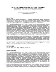
low surface loading rate to ensure fine and slowly settling grit particles are retained. Once sampling iscomplete, the size distribution and effective settling velocity or effective specific gravity of the grit samplemust be determined. Both characteristics are needed in order to have accurate data upon which to base asystem design.In the absence of site specific information, it is advisable to err on the side of conservatism. In mostcases, design should be based on the smallest practicable particle size which would typically be in the75-106 µm size range. Figure 2 below shows the size distribution of grit from various plants versus thesettling velocity of the grit particles expressed in sand equivalent size or SES (Wilson, Tchobanoglous,Griffiths, 2007). SES expresses the measured grit settling velocity in terms of the size of sand spherehaving the same settling velocity. SES is a method for normalizing all factors impacting settling velocity,such as size, shape, SG and agglomeration, to a known design point. The chart below shows that 106micron is a convergent point where shifts in settling velocity, carry velocity, particle impacts, etc. mergeinto a sensible design point. Relating to Figure #1, it can be seen a 100 micron cut point targets most ofthe grit entering the plant.FIGURE 2. SIZE DISTRIBUTION VS. SETTLING VELOCITY DISTRIBUTION AT MULTIPLE WWTPSLacking an adequate grit characterization, as is always the case in new construction, a design cut point of75-106 micron will generally remove 80-90% of the grit entering the treatment plant. Certain areas of thecountry are known for fine grit or ‘sugar sand’ in these areas, or regions that contain loess, the finer cutpoint of 75 micron should be used. Most other areas of the country will achieve adequate results with a106 micron design cut point particle. Reducing the design cut point particle effectively increases thesurface loading requirement four-fold allowing sufficient settling time to remove the fine and light grit thatpreviously has been overlooked, while the larger, heavier grit, that is transported to the treatment plantduring higher flows seen during diurnal flow cycles, seasonal variations and spikes in flow from wetweather events, is easily captured.SYSTEM DESIGNSeveral factors should be considered when designing a grit removal system starting with a fullcharacterization of the endemic grit including grit concentration, size distribution and settling velocity oreffective SG. Understanding the actual characteristics of grit at a particular plant facilitates properselection of the size and type of grit removal system that is required. With good data on the endemic grit,a cost benefit analysis can be determined, evaluating grit removal efficiency as compared to cost. Wherespecific data on endemic grit is not available a design cut point in the range of 75-106 micron willGrit Happens – You Don’t Know What You Are Missing
generally provide the plant with adequate protection by removing 80-90% of the grit entering thetreatment plant.Other considerations in this cost analysis would include upstream screening requirements, maintenancerequirements, available space, and anticipated headloss/hydraulic gradient through the process and thelevel of protection to be afforded to downstream equipment and processes. Table 2 outlines importantrecommended guidelines to use when designing or evaluating a grit removal system.TABLE 2. <strong>GRIT</strong> REMOVAL SYSTEM CRITICAL DESIGN FACTORSDesign GuidelineDefine Design Requirements:ü Grit Particle Size Analysisü Settling velocity or Specific Gravityü Required System Removal Efficiencyü Screening RequirementsRequired Downstream Protection:ü Biological Processesü Sludge Processing EquipmentEvaluate Equipment:ü Removal Efficiency/Performanceü Equipment Design/Featuresü Space Requirementsü Headloss Requirementsü Cost: Capital, Installed, Operationalü Maintenance RequirementsEMERGING TRENDHeadworks screening and grit removal is the primary protection for all treatment processes andequipment in a wastewater treatment plant, yet it has been the most neglected part of the plant. Toimprove solids removal screen openings on influent screens have trended progressively smaller over thepast 10-15 years. Years ago screen openings were frequently 1’ and larger. Today, screens arecommonly supplied with ¼” openings. It is logical that improving grit removal processes to effectivelyremove incoming grit is becoming a higher priority in plant designs.Biological processes have evolved to become more efficient and produce a cleaner effluent inprogressively smaller areas. As plants move toward higher performing processes, effective grit removalbecomes more important. The growing acceptance of Membrane Bio-Reactor (MBR) technology bringsthe need for advanced grit management systems into consideration. MBR technology requires extensivescreening pretreatment which protects the membrane and often allows elimination of primary clarification.Without the protection of primary clarification, advanced grit removal should also be part of effective MBRpretreatment system design (Andoh 2009). Grit entering a MBR plant can cause abrasive wear anddamage the membranes, which is often the most expensive equipment in the plant.Fine Bubble aeration is not a particularly advanced treatment process yet when a plant upgrades fromcoarse bubble aeration to fine bubble aeration, and in the process eliminates their primary clarifier, theimpact of grit deposition increases for two reasons. First, the velocity in the aeration basin is reduced asis the deposit limit, making it the first likely location in the process train for grit to accumulate. Secondly,the deposited grit creates new maintenance challenges as diffusers cover the full floor of the basin whichrestricts the ability to clean them and makes the cleaning process more operator intensive and expensive.Diffusers covered with grit are less effective and additional horsepower may be required to achievedesired results.Today many plants are requiring increased effectiveness of their grit removal systems and their designengineers are taking a closer look at the size and settling velocity distributions of grit entering theseplants. Newer editions of design manuals are recommending targeting particles smaller than 212 µm ingrit system design. In 2009, WEF MOP #8 issued a new chapter on Grit Removal stating that in 2008, aGrit Happens – You Don’t Know What You Are Missing
WEF member survey reported grit density ranged from 1100 to 2200 kg/m3 (70 – 140 lb/ft 3 ) and averaged1,400 kg/m3 (90 lb/ft 3 ). Metcalf & Eddy states that the specific gravity of clean grit reaches 2.7 for inertsbut can be as low as 1.3 when a substantial amount of organic material is agglomerated with inerts. Bulkdensity and specific gravity of wastewater grit is lower than these factors are for clean silica sandindicating a shift in design considerations. Grit is not clean sand and many grit removal systems beingdesigned today are targeting removal of particles in the 75-106-150 µm size range in order to remove theparticles that cause abrasive wear and deposit throughout the process.CONCLUSIONMany installed grit systems fail to keep depositable grit out of the plant. In fact, they fail to remove thesizes and amounts of grit they were designed to capture. Grit system failure happens primarily due to afaulty assumption that municipal grit behaves like clean silica sand particles in clean water. The failure ofmany traditional grit removal systems has led to the misconception that grit removal systems cannotwork, and that the only option is to deal with grit deposits in process basins downstream of the headworksand to deal with the abrasive wear from grit, both increasing maintenance and operational budgets.In order to design an effective system, design guidelines should be more comprehensive examining sizeand settling velocity of endemic grit, impact grit will have on downstream equipment and processes, gritsystem efficiency, headloss, space, cost, etc. A clear understanding of the grit entering the plant includesgrit concentration, size distribution, effective specific gravity and/or settling velocity. Only with a clearunderstanding of the material to be removed can a system be designed to achieve specified results.When a complete characterization of the endemic grit is not available a conservative approach canprovide effective grit removal. Targeting particles in the 75-100 micron range will typically remove 80-90% of the grit entering the treatment plant.Effective grit management requires a system approach. All components of the system must be effective inorder for the overall system to yield the desired results. Improving grit collection only to lose a majorportion of it back to the process in the washing and dewatering step is detrimental to overall removalefficiency and reduces the value of the entire system. Capturing a high percentage of the incoming gritload along with a high concentration of organics yields a product that is both difficult and expensive tolandfill and can starve downstream biological processes. Each step of the process is important andshould be optimally designed.Grit systems can work as intended when designed with an accurate understanding of the nature andcharacteristics of the grit arriving at the treatment plant and how this grit actually behaves in wastewater.An effective system addresses size as well as settling velocity or SG and produces a clean, dry productfor landfill. The result is abrasive wear on equipment and deposits and accumulations in the plant areminimized. In turn, money is saved on maintenance and operational costs and equipment and processesperform better.REFERENCESWilson, G., Tchobanoglous, G., and Griffiths, J. (2007) The Grit Book. Eutek Systems, Inc.: Hillsboro,Oregon.Massart, N., O’Kelley, S., Neun, G. (2010) Sustainable Biosolids Handling – Digester Cleaning, FloridaWater Resources Conference. May 2010Herrick, P. (2009) A Portable Solution for Degritting Aeration Basins. Pollution Equipment News. January2009, pp 17-18.Griffiths, J. (2004) Fox Lake Regional WRF Grit Testing Results. Grit Solutions. May 7, 2004 and August19, 2003.Boldt, J. (2005) Eliminating Grit Deposition Problems through Objective Grit System Design, A CaseStudy at the Fox lake NRWRP – Fox Lake, IL. Illinois WEA Conference. January 2005.Grit Happens – You Don’t Know What You Are Missing
Osei, K. and Andoh, R.Y.G, (2008) Optimal Grit Removal and Control in Collection Systems and atTreatment Plants, World Environmental and Water Resources Congress, Honolulu, Hawaii, 12-16 May.Boyrs, A., Gabb, D. and Hake, J. (2002) Performance Evaluation of Aerated Grit Chambers andProposed Modifications to Increase Grit Removal Efficiency at East Bay Municipal Utility District WWTP.Conference Proceedings from California Water Environment Association Annual Conference, April 4.Session 22.Jiminez, J. and Madsen, O. (2003) A Simple Formula to Estimate Settling Velocity of Natural Sediments.Journal of Waterway, Port, Coastal and Ocean Engineering, ASCE March/April 2003Andoh, R.Y.G. and Neumayer, A. (2009) Fine Grit Removal Helps Optimize Membrane Plants.WaterWorld. January 2009, pp 28.Reade Advanced Materials. Weight Per Cubic Foot and Specific Gravities. Reade Specialty ChemicalResource Company.http://www.reade.com/Particle_Briefings/spec_gra2.html (Accessed February 2010).Water Environment Federation and ASCE (2009) WEF Manual of Practice 8, 5 th Edition, Alexandria, VA,WEF, ASCE.Metcalf & Eddy, Inc, (2003) Wastewater Engineering: Treatment and Reuse, 4 th ed., McGraw-Hill.Grit Happens – You Don’t Know What You Are Missing