AIR CONDITIONER - Heronhill Air Conditioning Ltd
AIR CONDITIONER - Heronhill Air Conditioning Ltd
AIR CONDITIONER - Heronhill Air Conditioning Ltd

You also want an ePaper? Increase the reach of your titles
YUMPU automatically turns print PDFs into web optimized ePapers that Google loves.
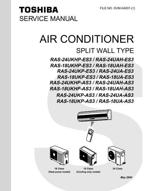
FILE NO. SVM-04007-(1)SERVICE MANUAL<strong>AIR</strong> <strong>CONDITIONER</strong>SPLIT WALL TYPERAS-24UKHP-ES3 / RAS-24UAH-ES3RAS-18UKHP-ES3 / RAS-18UAH-ES3RAS-24UKP-ES3 / RAS-24UA-ES3RAS-18UKP-ES3 / RAS-18UA-ES3RAS-24UKHP-AS3 / RAS-24UAH-AS3RAS-18UKHP-AS3 / RAS-18UAH-AS3RAS-24UKP-AS3 / RAS-24UA-AS3RAS-18UKP-AS3 / RAS-18UA-AS318 Class(Heat pump model)18 Class(Cooling only model)24 ClassMay 2004
CONTENTSFILE NO. SVM-04007-(1)1. SPECIFICATIONS2. CONSTRUCTION VIEWS2-1 Indoor Unit2-2 Outdoor Unit (RAS-24UAH-ES3, RAS-24UA-ES3, RAS-24UAH-AS3, RAS-24UA-AS3)2-3 Outdoor Unit (RAS-18UAH-ES3, RAS-18UAH-AS3)2-4 Outdoor Unit (RAS-18UA-ES3, RAS-18UA-AS3)3. WIRING DIAGRAM3-1 RAS-24UKHP-ES3 / RAS-24UAH-ES3, RAS-24UKHP-AS3 / RAS-24UAH-AS33-2 RAS-18UKHP-ES3 / RAS-18UAH-ES3, RAS-18UKHP-AS3 / RAS-18UAH-AS33-3 RAS-24UKP-ES3 / RAS-24UA-ES3, RAS-24UKP-AS3 / RAS-24UA-AS33-4 RAS-18UKP-ES3 / RAS-18UA-ES3, RAS-18UKP-AS3 / RAS-18UA-AS34. SPECIFICATION OF ELECTRICAL PARTS4-1 Indoor Unit (RAS-24UKHP-ES3, RAS-18UKHP-ES3, RAS-24UKHP-AS3, RAS-18UKHP-AS3)4-2 Outdoor Unit (RAS-24UAH-ES3, RAS-24UAH-AS3)4-3 Outdoor Unit (RAS-18UAH-ES3, RAS-18UAH-AS3)4-4 Indoor Unit (RAS-24UKP-ES3, RAS-18UKP-ES3, RAS-24UKP-AS3, RAS-18UKP-AS3)4-5 Outdoor Unit (RAS-24UA-ES3, RAS-24UA-AS3)4-6 Outdoor Unit (RAS-18UA-ES3, RAS-18UA-AS3)5. REFRIGERATION CYCLE DIAGRAM5-1 RAS-24UKHP-ES3 / RAS-24UAH-ES3, RAS-24UKHP-AS3 / RAS-24UAH-AS35-2 RAS-18UKHP-ES3 / RAS-18UAH-ES3, RAS-18UKHP-AS3 / RAS-18UAH-AS35-3 RAS-24UKP-ES3 / RAS-24UA-ES3, RAS-24UKP-AS3 / RAS-24UA-AS35-4 RAS-18UKP-ES3 / RAS-18UA-ES3, RAS-18UKP-AS3 / RAS-18UA-AS36. CONTROL BLOCK DIAGRAM6-1 RAS-24UKHP-ES3, RAS-18UKHP-ES3, RAS-24UKHP-AS3, RAS-18UKHP-AS36-2 RAS-24UKP-ES3, RAS-18UKP-ES3, RAS-24UKP-AS3, RAS-18UKP-AS37. OPERATION DESCRIPTION7-1 Outline of <strong>Air</strong> Conditioner Control7-2 Description of Operation Circuit7-3 Hi POWER Mode7-4 High-Temperature Limit Control7-5 Low-Temperature Limit Control7-6 Defrosting Operation7-7 Auto Restart Function7-8 Filter Check Lamp7-9 Self-Cleaning function8. INSTALLATION PROCEDURE8-1 Safety Cautions8-2 Installation Diagram of Indoor and Outdoor Units8-3 Installation8-4 Indoor Unit8-5 Outdoor Unit8-6 Others- 1 -
FILE NO. SVM-040079. TROUBLESHOOTING CHART9-1 Troubleshooting Procedure9-2 Basic Check Items9-3 Primary Judgement9-4 Self-Diagnosis by Remote Control (Check Code)9-5 How to Diagnose Faulty Part9-6 Troubleshooting for Indoor Unit9-7 Troubleshooting for Wiring (Interconnect cable and Serial Signal Wire)9-8 Troubleshooting for P.C. Board9-9 Troubleshooting for Remote Control10. PARTS REPLACEMENT10-1 Indoor Unit10-2 Outdoor Unit (RAS-24UAH-ES3, RAS-24UA-ES3, RAS-24UAH-AS3, RAS-24UA-AS3)10-3 Outdoor Unit (RAS-18UAH-ES3, RAS-18UAH-AS3)10-4 Outdoor Unit (RAS-18UA-ES3, RAS-18UA-AS3)11. EXPLODED VIEWS AND PARTS LIST11-1 Indoor Unit (E - Parts Assy)11-2 Indoor Unit11-3 Outdoor Unit (RAS-24UAH-ES3, RAS-24UAH-AS3)11-4 Outdoor Unit (RAS-18UAH-ES3, RAS-18UAH-AS3)11-5 Outdoor Unit (RAS-24UA-ES3, RAS-24UA-AS3)11-6 Outdoor Unit (RAS-18UA-ES3, RAS-18UA-AS3)• This air conditioner is charged withHFC (R410A) that doesn't deplete theOzone layer.• This air conditioner requires specialinstallation for the refrigerant R410A.- 2 -
Note : 1· Capacity is based on the following temperature conditions.FILE NO. SVM-04007TemperatureIndoor unit inlet air temperatureOutdoor unit inlet air temperatureConditionJIS C9612-1994CoolingHeating(DB) 27°C 20°C(WB) 19°C 15°C(DB) 35°C 7°C(WB) 24°C 6°CNote : 2· Charge refrigerant according to the table below.Refrigerant*1 No need to chargeextra refrigerant*2 Need to chargeextra refrigerantRAS-24UKHP-ES3 / RAS-24UAH-ES3 RAS-18UKHP-ES3 / RAS-18UAH-ES3RAS-24UKP-ES3 / RAS-24UA-ES3 RAS-18UKP-ES3 / RAS-18UA-ES3RAS-24UKHP-AS3 / RAS-24UAH-AS3 RAS-18UKHP-AS3 / RAS-18UA-AS3RAS-24UKP-AS3 / RAS-24UA-AS3 RAS-18UKP-AS3 / RAS-18UA-AS315m or lessOver 15m up to 25m (20g/m)15m or lessOver 15m up to 20m (20g/m)- 5 -
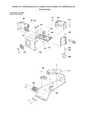
FILE NO. SVM-040072-3. Outdoor Unit (RAS-18UAH-ES3, RAS-18UAH-AS3)A Detail Drawing600R10∅6 hole∅11x14 hole∅420AFan guard∅25 Drain outletInstallation dimension100 or more600<strong>Air</strong> inlet600 or more<strong>Air</strong> inlet3255035100 or more<strong>Air</strong>outlet600 ormore4x∅11x14for ∅8-∅10anchor bolt8-∅6 holes(for fixing outdoor unit)6-∅11x14 holesor ∅8 — ∅10 anchor bolt)ElectricParts coverLiquid side(Flare ∅6.35)Gas side(Flare ∅12.7)91 54901206008309050603442353832552300Service PortHandle– 8 –
2-4. Outdoor Unit (RAS-18UA-ES3, RAS-18UA-AS3)FILE NO. SVM-04007HandleFan guard∅420906009078065.5538300A120∅25Drain outlet4-∅11x14 hole(for Ø8-Ø10 anchor bolt)8-∅6 hole(for fixing outdoor unit)27100 or moreInstallation dimension600<strong>Air</strong> inlet600 or more<strong>Air</strong> inlet100 or more<strong>Air</strong>outlet600 ormore 4x∅11x14or ∅8-∅10anchor boltElectric parts coverLiquid side(Flare ∅6.35)Gas side(Flare ∅12.7)ServicePort3443013252332552.5130100325ADetail Drawing5035600R10∅6 hole∅11x14 hole– 9 –
3. WIRING DIAGRAMFILE NO. SVM-040073-1. RAS-24UKHP-ES3 / RAS-24UAH-ES3 , RAS-24UKHP-AS3 / RAS-24UAH-AS3BLKWHIREDBLKP04CN31CN30COLOR IDENTIFICATIONBRW : BROWNRED : REDWHI : WHITEYEL : YELLOWBLU : BLUEBLK : BLACKGRY : GRAYPNK : PINKORN : ORANGEGRN&YEL : GREEN &YELLOWGRN : GREENR22SG01 VARISTORDSAT6. 3A 250VF01 FUSER09R21LOUVERMOTORIC04C15L01R01C01BLUPNKYELORNREDBRW6 5 4 3 2 1 6 5 4 36 5 4 3 2 1 6 5 4 3CN 07 CN 10DB01MAIN P.C. BOARD(MCC-821)C02FAN MOTORDC MOTORC06T0111IC02DC15VDC0VDC12VDC7VDC0VGRN&YELCN23CN13CN03 CN011 2 3 4 5 6 7 8 9 10 1 21 2BLU1THERMO1 2 3 4 5 6 7 8 9 10SENSOR1 2 3 4CN255 6 7 8 9 10(TA)2 3 4 5 6 7 8 9 10 1 21 2INFRARED RAYS RECEIVEAND INDICATION PARTSBLUBLUBLUBLUBLUBLUBLUBLUWHIBLKBLKICIC01BLKBLKHEATEXCHANGERSENSOR(TC)OUTDOORTERMINALBLOCKBLK1 2L N i 1 2 3FERRITE COREBLKREDGRN&YELREDINDOORTERMINALBLOCKPOWER SUPPLY220-240 V~ 50 Hz3iCHASSISINDOORUNITOUTDOORUNITGRN&YELTRANSFORMERBLK1 12 CN06BLK3 3RED1 1REDCN053 3TNRSG01 R74BLK 1 1BLKF013 3250VAC T6. 3AWHI5 5RED CN017 7GRY 9 9MAIN P.C. BOARD (MCC-890)TNRR73DISCHARGEPIPESENSOR (TD)BLU1 1CN07 23 3BLUBLK1 1CN08 23 3BLKHEATEXCHANGERSENSOR (TE)REDR(1/L1)(2/T1)UMAGNETICCONTACTORCAPACITORS(3/L2)(4/T2)VTA1(5/L3)52C(6/T3)A2WREDCAPACITORBLU 1 1CN113 3YELBLU1 1CN023 3BLUCOIL FOR4 WAY VALVECR11CR12CR13RY07RY05RY06CS RCOMPRESSOR TERMINALWHIPNKSRCCOMPRESSORBLKWHIREDBLKFAN MOTORBLKCN031 31– 10 –
FILE NO. SVM-040073-4. RAS-18UKP-ES3 / RAS-18UA-ES3, RAS-18UKP-AS3 / RAS-18UA-AS3BLKWHIREDBLKP04CN30CN31CN271 13COLOR IDENTIFICATIONBRW : BROWNRED : REDWHI : WHITEYEL : YELLOWBLU : BLUEBLK : BLACKGRY : GRAYPNK : PINKORN : ORANGEGRN&YEL GREEN & YELLOWGRN : GREENR22SG01 VARISTORDSAT6.3A 250 VF01 FUSERY04R09R21LOUVERMOTORIC04C15L01R01C01BLUPNKYELORNREDBRW6 5 4 3 2 1 6 5 4 36 5 4 3 2 1 6 5 4 3CN 07 CN 10DB01MAIN P.C. BOARD(MCC-821)+C02FAN MOTORDC MOTORC06T0111IC02DC15VDC0VDC12VDC7VDC0VGRN&YELCN131 2 3 4 5 6 7 8 9 101 2 3 4 5 6 7 8 9 10ICIC01CN031 21 2CN011 21 2BLUBLUBLUBLUBLUBLUBLUBLUBLUWHIBLKBLK1 2 3 4 5 6 7 8 9 101 2 3 4CN255 6 7 8 9 10INFRARED RAYS RECEIVEAND INDICATION PARTSTHERMOSENSOR(TA)BLKBLKHEATEXCHANGERSENSOR(TC)INDOORTERMINALBLOCK1 23INDOORUNITPOWER SUPPLY220 − 240 V ~ 50 HzOUTDOORUNITOUTDOORTERMINALBLOCKL N 1 2 3BLKREDGRN&YELBLKBLKGRN&YELBLKREDREDCHASSISSPARK KILLERGRYR S TA1(or A)MAGNETICCONTACTORU V WA2 (or B)REDCAPACITORREDCAPACITORSWHI CPNKBLKRCOMPRESSORCWHIREDBLKFAN MOTORRSCOMPRESSOR TERMINAL− 13 −
3-5. RAS-24UKP-AS3 / RAS-24UA-AS3FILE NO. SVM-04007BLKWHIREDBLKP04CN30CN31CN271 13COLOR IDENTIFICATIONBRW : BROWNRED : REDWHI : WHITEYEL : YELLOWBLU : BLUEBLK : BLACKGRY : GRAYPNK : PINKORN : ORANGEGRN&YEL : GREEN & YELLOWGRN : GREENR22SG01 VARISTORDSAT6.3A 250 VF01 FUSERY04R09R21LOUVERMOTORIC04C15L01R01C01BLUPNKYELORNREDBRW6 5 4 3 2 1 6 5 4 36 5 4 3 2 1 6 5 4 3CN 07 CN 10DB01MAIN P.C. BOARD(MCC-821)C02FAN MOTORDC MOTORC06T0111IC02DC15VDC0VDC12VDC7VDC0VGRN&YELCN131 2 3 4 5 6 7 8 9 101 2 3 4 5 6 7 8 9 10ICIC01CN031 21 2CN011 21 2BLUBLUBLUBLUBLUBLUBLUBLUBLUWHIBLKBLK1 2 3 4 5 6 7 8 9 101 2 3 4CN255 6 7 8 9 10INFRARED RAYS RECEIVEAND INDICATION PARTSTHERMOSENSOR(TA)BLKBLKHEATEXCHANGERSENSOR(TC)INDOORTERMINALBLOCK1 23INDOORUNITPOWER SUPPLY220 − 240 V ~ 50 HzOUTDOORUNITOUTDOORTERMINALBLOCKL N 1 2 3GRN&YELBLKBLKREDREDCHASSISBLKBLKGRYSPARK KILLERREDA1 52C A2R US VREDREDELECTRICSTARTERWHICAPACITORWHISTARTINGCAPACITORREDWHIPNKCAPACITORSRC BLKWHIREDFAN MOTORRCSBLKTWCOMPRESSORCOMPRESSOR TERMINALMAGNETIC CONTACTOR− 14 −
4. SPECIFICATION OF ELECTRICAL PARTSFILE NO. SVM-040074-1. Indoor Unit (RAS-24UKHP-ES3, RAS-18UKHP-ES3, RAS-24UKHP-AS3, RAS-18UKHP-AS3)No. Parts name Type Specifications1 Fan motor (for indoor) ICF-340-30-2 DC 340V, 30W2 Thermo sensor (TA-sensor) ——— 10kΩ at 25°C3 DC-DC transformer (T01) SWT-58A DC 390V, Secondary DC 15V, 12V, 7V4 Microcontroller TMP87CM40AN5 Heat exchanger sensor(TC-sensor)——— 10kΩ at 25°C6 Line filter (L01) SS11V-R07190 19mH, AC 0.7A7 Diode (DB01) D3SBA60 4A, 600V8 Capacitor (C02) KMH450VNSN120M25C 120 µF, 450V9 Fuse (F01) TSCR T6.3A, 250V10 Power supply IC (IC01) MA8920 5A, 900V11 Varistor (R21, R22) 15G561K 560V12 Resistor (R01) RF-5TK4R7B 4.7Ω, 5W13 Louver motor MP35EA12 Output (Rated) 2W, 10poles, 4phase,DC 12V4-2. Outdoor Unit (RAS-24UAH-ES3, RAS-24UAH-AS3)No. Parts name Type SpecificationsOutput (Rated) 2200W, 2poles, 1 phase, 220 − 240V, 50Hz1 Compressor PA290X3F-4MS Winding resistance (Ω) Red-Black White-Black(at 20°C) 1.07 2.20Output (Rated) 65W, 6poles, 1 phase, 220 – 240V, 50Hz2 Fan motor (for outdoor) KFG6-71SB5P-T1 Winding resistance (Ω) Red-Black White-Black(at 20°C) 64.4 127.43Running capacitor(for fan motor)451355KQ AC 450V, 3.5µF4Running capacitor(for compressor)371456JCR AC 370V, 45µF5Solenoid coil(for 4-way valve)VHV (STF) AC 220 ~ 240V6 Thermo sensor TE / TD 10kΩ at 25°C / 50kΩ at 25°C7 Magnetic contactor CLK-35J 220 ~ 240V, 50Hz8 Transformer TT-05 220 ~ 240V9 Microcontroller TMP47C840N10 Varistor (R73, R74) 15G471K 470V11 Fuse (F01) TSCR T6.3A, 250V– 15 –
4-3. Outdoor Unit (RAS-18UAH-ES3, RAS-18UAH-AS3)FILE NO. SVM-04007No. Parts name Type SpecificationsOutput (Rated) 1500W, 2poles, 1 phase, 220 − 240V, 50Hz1 Compressor PA225X3F-4L Winding resistance (Ω) Red-Black White-Black(at 20°C) 1.35 2.68Output (Rated) 65W, 6poles, 1 phase, 220 – 240V, 50Hz2 Fan motor (for outdoor) HF-240-42B-2 Winding resistance (Ω) Red-Black White-Black(at 20°C) 176.2 290.53Running capacitor(for fan motor)451205KQ AC 450V, 2µF4Running capacitor(for compressor)371456JCR AC 370V, 45µF5Solenoid coil(for 4-way valve)VHV (STF) AC 220 − 240V6 Thermo sensor TE / TD 10kΩ at 25°C / 50kΩ at 25°C7 Magnetic contactor CLK-26J 220 − 240V, 50Hz8 Transformer TT-05 220 − 240V9 Microcomputer TMP47C840N10 Varistor (R73, R74) 15G471K 470V11 Fuse (F01) TSCR T6.3A, 250V4-4. Indoor Unit (RAS-24UKP-ES3, RAS-18UKP-ES3, RAS-24UKP-AS3, RAS-18UKP-AS3)No. Parts name Type Specifications1 Fan motor (for indoor) ICF-340-30-2 DC 340V, 30W2 Thermo sensor (TA-sensor) ——— 10kΩ at 25°C3 DC-DC transformer (T01) SWT-58A DC 390V, Secondary DC 15V, 12V, 7V4 Microcontroller TMP87CM40AN5 Heat exchanger sensor(TC-sensor)——— 10kΩ at 25°C6 Line filter (L01) SS11V-R07190 19mH, AC 0.7A7 Diode (DB01) D3SBA60 4A, 600V8 Capacitor (C02) KMH450VNSN120M25S 120µF, 450V9 Fuse (F01) TSCR T6.3A, 250V10 Relay (for outdoor fan motor,solenoid coil) (RY04)AJQ134111 Power supply IC (IC01) MA8920 5A, 900V12 Varistor (R21, R22) 15G561K 560V13 Resistor (R01) RF-5TK4R7B 4.7Ω, 5WCoil DC 12V, 33mA, Rated 1A, AC 250V14 Louver motor MP35EA12 Output (Rated) 2W,10poles, 4phase,DC 12V– 16 –
5. REFRIGERATION CYCLE DIAGRAM5-1. RAS-24UKHP-ES3 / RAS-24UAH-ES3RAS-24UKHP-AS3 / RAS-24UAH-AS3FILE NO. SVM-04007CoolingIndoor unitHeat exchangerT10.49m(Connecting pipe)∅12.7HeatingCross flow fan0.39m(Connecting pipe)∅6.35O.D.:12.7mmPO.D.:6.35mmCoolingPacked valve(∅12.7)Gas container connection (Reinstall etc.)Heating4-way valvePacked valve(∅6.35)Heating Cooling CompressorPA290X3F-4MSTankCapillary tube∅2.0x700sCondenserCoolingHeatingPropeller fanOutdoor unitMark(RefrigerantR410A 1.6 kg)means check points of Gas Leak.50HzStandardpressure P(MPaG)Surface temp. of heatexchanger interchangingpipe T1 (°C)Note :• Measure the heat exchanger temperature at the center of U-bend. (By means of TC sensor)*1 • During heating overload operation, a value for the high temperature limit control operation is included.– 18 –Fan speed(indoor)Ambient temp.conditions DB/WB(°C)IndoorOutdoorStandard 2.7 43.0 High 20/– 7/6Heating Overload*1 3.1 ~ 4.0 52.0 ~ 59.0 Low 27/– 24/18Low temperature 2.7 36.0 High 20/– –10/–10Standard 0.9 11.0 High 27/19 35/24Cooling Overload 0.8 12.0 High 32/23 43/26Low temperature 0.5 1.0 Low 21/15 21/15
FILE NO. SVM-040075-2. RAS-18UKHP-ES3 / RAS-18UAH-ES3RAS-18UKHP-AS3 / RAS-18UAH-AS3CoolingIndoor unitEvaporatorT10.39m(Connecting pipe)∅12.7HeatingCross flow fan0.49m(Connecting pipe)∅6.35O.D.:12.7mmPO.D.:6.35mmPacked valve(∅12.7)Packed valve(∅6.35)CoolingHeating4-way valveHeating Cooling CompressorPA225X3F-4LAccumulatorCapillary tube∅1.7x700sCapillary tube∅1.0x1500sCondenserCoolingHeatingPropeller fanOutdoor unitMark(RefrigerantR410A 1.3 kg)means check points of Gas Leak.50HzStandardpressure P(MPaG)Surface temp. of heatexchanger interchangingpipe T1 (°C)Fan speed(indoor)Ambient temp.conditions DB/WB(°C)IndoorOutdoorStandard 2.7 45.0 High 20/– 7/6Heating Overload*1 3.0 ~ 3.8 49.0 ~ 58.0 Low 27/– 24/18Low temperature 2.0 34.0 High 20/– –10/–10Standard 0.9 10.0 High 27/19 35/24Cooling Overload 1.0 15.0 High 32/23 43/26Low temperature 0.6 1.0 Low 21/15 21/15Note :• Measure the heat exchanger temperature at the center of U-bend. (By means of TC sensor)*1 • During heating overload operation, a value for the high temperature limit control operation is included.– 19 –
5-3. RAS-24UKP-ES3 / RAS-24UA-ES3RAS-24UKP-AS3 / RAS-24UA-AS3FILE NO. SVM-04007CoolingIndoor unitHeat exchangerT10.49m(Connecting pipe)∅12.7Cross flow fan0.39m(Connecting pipe)∅6.35O.D.:12.7mmPO.D.:6.35mmPacked valve(∅12.7)Gas container connection (Reinstall etc.)Packed valve(∅6.35)CoolingCooling Compressor5JS315DAG01TankCapillary tube∅2.0x700sCondenserRefrigerantCoolingPropeller fanOutdoor unitMark(R410A 1.6kg)means check points of Gas Leak.50HzStandardpressure P(MPaG)Surface temp. of heatexchanger interchangingpipe T1 (° C)Fan speed(indoor)Note :• Measure the heat exchanger temperature at the center of U-bend. (By means of TC sensor)Ambient temp.conditions DB/WB(° C)IndoorOutdoorStandard 0.9 6.0 High 27/19 35/24Cooling Overload 0.8 10.0 High 32/23 43/26Low temperature 0.6 2.0 Low 21/15 21/15– 20 –
5-4. RAS-18UKP-ES3 / RAS-18UA-ES3RAS-18UKP-AS3 / RAS-18UA-AS3FILE NO. SVM-04007CoolingIndoor unitEvaporatorT10.39m(Connecting pipe)∅12.7Cross flow fan0.49m(Connecting pipe)∅6.35O.D.:12.7mmPO.D.:6.35mmPacked valve(∅12.7)Packed valve(∅6.35)CoolingCooling Compressor5KS225DAACapillary tube∅1.7x600sCondenserRefrigerantCoolingPropeller fanOutdoor unitMark(R410A 1.14 kg)means check points of Gas Leak.50HzStandardpressure P(MPaG)Surface temp. of heatexchanger interchangingpipe T1 (°C)Fan speed(indoor)Note :• Measure the heat exchanger temperature at the center of U-bend. (By means of TC sensor)Ambient temp.conditions DB/WB(°C)IndoorOutdoorStandard 0.9 10.0 High 27/19 35/24Cooling Overload 1.0 13.0 High 32/23 43/26Low temperature 0.6 2.0 Low 21/15 21/15– 21 –
6. CONTROL BLOCK DIAGRAMFILE NO. SVM-040076-1. RAS-24UKHP-ES3, RAS-18UKHP-ES3 / RAS-24UKHP-AS3, RAS-18UKHP-AS3Heat Exchanger SensorIndoor Unit Control PanelFunctions• Louver ControlM.C.U.OperationDisplayTemperature Sensor• 3-minute Delay at Restart for CompressorTimerDisplayInfrared Rays Signal ReceiverInfraredRaysInitiallizing CircuitClock FrequencyOscillator Circuit• Motor Revolution Control• 20 sec Self Cleaning Function• Processing(Temperature Processing)• Timer• Serial Signal CommunicationFilter SignDisplayPRE DEF.Sign DisplayHi PowerSign DisplayIndoorFan MotorRemoteControlPower SupplyCircuitLouver ON/OFF SignalNoise FilterLouver DriverLouver MotorSerial Signal Transmitter/ReceiverFrom Outdoor Unit220 ~ 240V AC 50HzSerial Signal CommunicationREMOTE CONTROLRemote ControlInfrared RaysOperation (START/STOP)Operation Mode SelectionAUTO, COOL, DRY, HEAT, FAN ONLYTemperature SettingFan Speed SelectionON TIMER SettingOFF TIMER SettingLouver Auto SwingLouver Direction SettingECOHi powerFilter Reset– 22 –
FILE NO. SVM-040076-2. RAS-24UKP-ES3, RAS-18UKP-ES3 / RAS-24UKP-AS3, RAS-18UKP-AS3Indoor Unit Control PanelM.C.U.Heat Exchanger SensorFunctions Louver ControlOperationDisplayTemperature Sensor 3-minute Delay at Restart for CompressorTimerDisplayInfrared Rays Signal ReceiverInfraredRaysInitiallizing CircuitClock FrequencyOscillator Circuit Motor Revolution Control20 sec Self Cleaning function Processing(Temperature Processing) TimerFilter SignDisplayFan OnlySign DisplayHi PowerSign DisplayIndoorFan MotorRemoteControlPower SupplyCircuitOutdoor unitON/OFF SignalLouver ON/OFF SignalNoise FilterRelay DriverLouver DriverLouver MotorRelay RY04From Outdoor Unit220 ~ 240V AC 50HzOutdoor UnitREMOTE CONTROLRemote ControlInfrared RaysOperation (START/STOP)Operation Mode SelectionAUTO, COOL, DRY, FAN ONLYTemperature SettingFan Speed SelectionON TIMER SettingOFF TIMER SettingLouver Auto SwingLouver Direction SettingECOHi powerFilter Reset− 23 −
7. OPERATION DESCRIPTIONFILE NO. SVM-040077-1. Outline of <strong>Air</strong> Conditioner ControlThis is a fixed capacity type air conditioner, which usesa DC motor for an indoor fan. The DC motor drivecircuit is mounted in the indoor unit. And electricalparts which operate the compressor and the outdoorfan motor, are mounted in the outdoor unit.The air conditioner is mainly controlled by the indoorunit controller. The controller operates the indoor fanmotor based upon commands transmitted by theremote control and transfers the operation commandsto the outdoor unit controller.The outdoor unit controller receives operationcommands from the indoor unit, and operates theoutdoor fan motor and the compressor.(1) Role of indoor unit controllerThe indoor unit controller receives the operationcommands from the remote control and executesthem.· Temperature measurement at the air inlet of theindoor heat exchanger by the indoortemperature sensor· Temperature setting of the indoor heatexchanger by the heat exchanger sensor· Louver motor control· Indoor fan motor operation control· LED display control· Transferring of operation commands to theoutdoor unit· Receiving of information of the operation statusand judging of the information or indication oferror(2) Role of outdoor unit controllerThe outdoor unit controller receives the operationcommands from the indoor controller andexecutes them.· Compressor operationcontrol· Operation control ofoutdoor fan motorfOperations accordingto the commandsfrom the indoor unit· Turning off the compressor and outdoor fanwhen the outdoor unit receives the shutdowncommand· Defrost control in heating operation(Temperature measurement by the outdoor heatexchanger and control for the four-way valveand the outdoor fan motor) *Heat pump Modelonly7-1-1. Louver control(1) Vertical air flow louverPosition of veritcal air flow louver is automaticallycontrolled according to the operation mode.Besides, position of vertical air flow louver can bearbitrarily set by pressing [FIX] button.The louver position which is set by [FIX] button isstored in the microcomputer, and the louver isautomatically set at the stored position for the nextoperation.(2) SwingIf [SWING] button is pressed when the indoor unitis in operation, the vertical air flow louver startsswinging. When [FIX] button is pressed, it stopsswinging.7-1-2. Indoor fan control (DC Fan motor)(1) The indoor fan is operated by the stepless speedchange DC motor.(2) For air flow level, speed of the indoor fan motor iscontrolled in five steps (LOW, LOW + , MED, MED +and HIGH). If AUTO mode is selected, the fanmotor speed is automatically controlled by thedifference between the preset temperature andthe room temperature.Table 7-1-1RAS-24UKHP-ES3RAS-24UKHP-AS3RAS-18UKHP-ES3RAS-18UKHP-AS3MODEL Motor speed <strong>Air</strong> flow level Motor speed <strong>Air</strong> flow level(rpm) (m 3 /h) (rpm) (m 3 /h)Cooling HIGH 1350 950 1150 750and MED 1150 750 1050 650Fan only LOW 1000 600 900 530HIGH 1350 950 1200 800Heating MED 1200 800 1100 700MODELLOW 1050 650 950 570RAS-24UKP-ES3RAS-24UKP-AS3RAS-18UKP-ES3RAS-18UKP-AS3Cooling HIGH 1350 950 1150 750and MED 1150 750 1050 650Fan only LOW 1000 600 900 530LOW + =MED + =LOW+MED2MED+HIGH2– 24 –
7-2. Description of Operation Circuit(1) When turning on the breaker, the operation lampblinks. This means that the power is on (or thepower supply is cut off.)(2) When pressing [START / STOP] button on theremote control, receiving beep sounds from theindoor unit, and the next operation is performedtogether with opening the vertical air flow louver.(3) Once the operation mode is set, it is memorized inthe microcomputer so that the previous operationcan be effected thereafter simply by pressing[START / STOP] button.7-2-1. Fan only operation([MODE] button on the remote control is setto the fan only operation.)(1) When [FAN] button is set to AUTO, the indoor fanmotor operates as shown in Fig. 7-2-1. When[FAN] button is set to LOW, LOW + , MED, MED + orHIGH, the motor operates with a constant air flow.FILE NO. SVM-040077-2-2. Cooling operation([MODE] button on the remote control is setto the cooling operation.)(1) The compressor, 4-way valve, outdoor fan andoperation display lamp are controlled as shown inFig. 7-2-2.Presettemp.0.50ONONOFF ON OFF OFF ONCompressorCommon relay4-way valve(Heat pump model)Outdoor fanOPERATIONdisplay lamp(Room temp.) - (Preset temp.)+3+2.5+2+1.5+1NOTE :*1: The values marked with *1 are calculated andcontrolled by the difference in motor speedbetween M+ and L-.Fig. 7-2-1 Setting of air flow [FAN:AUTO](2) ECO operation cannot be set.M+*1*1*1Fig. 7-2-2(2) When [FAN] button is set to AUTO, the indoor fanmotor operates as shown in Fig. 7-2-3. When[FAN] button is set to LOW, LOW + , MED, MED + orHIGH, the motor operates with a constant air flow.+0.5+3M+Preset 0+2.5temp. *1+2*1+1.5(Preset temp.: 24°C)*1+1(Room temp.) - (Preset temp.)Presettemp.+0.50-0.5NOTE :*1: The values marked with *1 are calculated andcontrolled by the difference in motor speedbetween M+ and L-.Fig. 7-2-3 Setting of air flow [FAN:AUTO]- 25 -
7-2-3. Dry operation([MODE] button on the remote control is setto the dry operation.)(1) The compressor, 4-way valve, outdoor fan andoperation display lamp are controlled as shown inFig. 7-2-4.FILE NO. SVM-040077-2-4. Heating operation *Heat pump model only([MODE] button on the remote control is setto the heating operation.)(1) The compressor, 4-way valve, outdoor fan andoperation display lamp are controlled as shown inFig. 7-2-6.+3+2ON:6min.OFF:4min.ON:5min.OFF:5min.ON OFFON:6min.OFF:4min.ON:5min.OFF:5min.ONPresettemp.OFF ONON OFF ON+1Presettemp.0OFFCompressorCommon relayOFF4-way valveOutdoor fanOPERATIONdisplay lampONCompressorCommon relay4-way valveONOutdoor fanOPERATIONdisplay lampFig. 7-2-4(2) The microprocessor turns the compressor on andoff at the regular intervals (4 to 6 minutes). Whilethe compressor is turning off, the indoor fan motoroperates in the SUPER LOW position.The pattern of operation depending on the relationbetween room temperature and presettemperatures is shown in Fig. 7-2-5.Room temp.Preset temp.+1Preset temp.Fig. 7-2-6(2) When [FAN] button is set to AUTO, the indoor fanmotor operates as shown in Fig. 7-2-7. When[FAN] button is set to LOW, LOW + , MED, MED + orHIGH, the motor operates with a constant air flow.Presettemp.0-0.5-1-1.5-2L*1*2M +CompressorOutdoor fanON ON ON ONOFF OFF OFFIndoor fan L. *S.L. L. S.L. L. S.L. L.*Super LowFig. 7-2-5-5.0-5.5[FAN AUTO]*1, *2 : The values marked with *1 and *2 arecalculated and controlled by the difference inmotor speed between M+ and L.Fig. 7-2-7 Setting of air flo w [FAN:AUTO]H(3) [FAN] button on the remote control is set to AUTOonly.(4) The ECO and Hi Power operations can not be set.- 26 -
(3) The indoor heat exchanger restricts revolvingspeed of the fan motor to prevent a cold draft. Theupper limit of the revolving speed is shown inFig. 7-2-8 and Table 7-2-1.*2NOTES :*1: The fan stops for 2 minutes after thermostat-OFF.*2: A is 24°C when the preset temperature is 24°C ormore and A is the preset temperature when it isunder 24°C.*3: SUL means Super Ultra Low.*4: Calculated from difference in motor speedbetween SUL and HIGH.*5 and *6:Fig. 7-2-8 Cold draft preventing controlTable 7-2-1Fan *5 *6speed Starting period Stabilized periodAUTO4645343333 2132 20A+4 A+4A-8 A-8*6 *5• Up until 12 minutespassed after startingthe unit• From 12 to 25 minutespassed after startingthe unit and roomtemperature is 3°Clower than presettemperatureManual • Room temperature(L - H) < Preset temperature-4°CAUTO*4SUL* 3SUL*1StopManual(One of5 steps)L-H(Up tosettingspeed)• From 12 to 25 minutespassed after startingthe unit and roomtemperature isbetween presettemperature and 3°Clower than presettemperature• 25 minutes or morepassed after startingthe unit• Room temperaturePreset temperature-3.5°CFILE NO. SVM-040077-2-5. Automatic operation([MODE] button on the remote control is setto the automatic operation.)(1) One of 3 operations (Cooling, Fan only or Heating)is selected according to difference between thepreset temperature and the room temperature atwhich the automatic operation has started, asshown in Fig. 7-2-9. The Fan only operationcontinues until the room temperature reaches alevel at which another mode is selected.(2) Temporary AutoWhen the TEMPORARY button on the indoor unitis pushed, the preset temperature is fixed at 24°Cand the indoor unit is controlled as shown inFig. 7-2-9.(Room temp.) - (Preset temp.)C+40Cooling operationThe louver moves to the position sameas Hi POWER operation.Heating operationRAS-24UKHP-ES3RAS-18UKHP-ES3RAS-24UKHP-AS3RAS-18UKHP-AS3Cooling operationFan only operationFig. 7-2-9RAS-24UKP-ES3RAS-18UKP-ES3RAS-24UKP-AS3RAS-18UKP-AS3- 27 -
7-3. Hi POWER Mode([Hi POWER] button on the remotecontrol is pressed.)When [Hi POWER] button is pressed while the indoorunit is in Auto, Cooling or Heating operation,Hi POWER mark is indicated on the display of theremote control and the unit operates as follows.(1) Automatic operation· The indoor unit operates in according to thecurrent operation.(2) Cooling operation· The preset temperature drops 1°C.(The value of the preset temperature on theremote control does not change.)· If the difference between the presettemperature and the room temperature is big,the horizontal louver moves to the Hi POWERposition automatically. Then when the differencebetween them gets smaller, the horizontallouver returns automatically.·FAN speed : [AUTO]If the difference between the presettemperature and room temperature is big, theair conditioner operates at maximum airflowlevel. If the difference between the presettemperature and the room temperature is small,the air conditioner operates at normal airflowlevel.· FAN speed : One of 5 levelsThe air conditioner operates at normal airflowlevel.(3) Heating operation *Heat pump model only·The preset temperature increases 2°C,(The value of the preset temperature on theremote control does not change.)·The indoor unit operates in normal heatingmode except the preset temperature is higher(+2°C).(4) The Hi POWER mode can not be set in Dry orFan only operation.·FILE NO. SVM-040077-4. High-Temperature Limit Control*Heat pump model onlyThe microcontroller detects the indoor heat exchangertemperature to prevent pressure of a refrigerating cyclefrom increasing excessively.The compressor and outdoor fan motor are controlledas shown in Fig. 7-4-1.CompressorOFFONONOutdoor fanOFFOFFONFig. 7-4-17-5. Low-Temperature Limit ControlThe microcontroller detects the indoor heat exchangertemperature to prevent the indoor heat exchanger fromfreezing.The compressor and outdoor fan motor are controlledas shown in Fig. 7-5-1.Heat exchangertemperature62Fig. 7-5-1Heat exchangertemp.7-6. Defrost Operation *Heat pump model onlyWhen the indoor unit is in heating operation, if therefrigerant evaporation temperature detected by theoutdoor heat exchanger sensor is under the specifiedtemperature, the outdoor unit starts the defrostingoperation. At this time, the 4-way valve relay and theoutdoor fan motor are turned off. The indoor fan motoris also turned off by the cold draft preventing control ofthe indoor microcomputer. Then, [PRE. DEF.] lamp onthe indoor unit comes on.The defrosting operation stops and the 4-way valverelay, outdoor fan motor and the indoor fan motor areturned on automatically when the refrigerantevaporation increases to the specified temperature, orwhen the defrosting time is over 12 minutes.605552Compressor Outdoor fanONLess than continuesfor 5 minutesOFF- 28 -
→ →→ →7-7-2. How to cancel auto restart functionTo cancel auto restart function, proceed as follows:Repeat the setting prodedure: the unit receives thesignal and beeps three times.The unit will be required to be turned on with theremote control after the main power supply is turnedoff.FILE NO. SVM-04007When the unit is on standby (Not operating)OperationPush [TEMPORARY] button for more The unit is on standby.than three seconds.Motions03SThe unit starts to operate.The orange lamp is on.After approx. three seconds,The unit beeps three times The lamp changes fromand continues to operate.orange to green.TEMPORARY buttonIf the unit is not required to operate at this time, push [TEMPORARY]button once more or use the remote control to turn it off.When the unit is in operationOperationMotionsPush [TEMPORARY] button for more The unit is in operation. The orange lamp is on.than three seconds.03SThe unit stops operating.The orange lamp is turned off.After approx. three seconds,The unit beeps three times.TEMPORARY buttonIf the unit is required to operate at this time, push [TEMPORARY]button once more or use the remote control to turn it on.• While this function is being set, if the unit is inoperation, the orange lamp is on.7-7-3. Power failure during timer operationWhen the unit is in Timer operation, if it is turned offbecause of power failure, the timer operation iscancelled. Therefore, set the timer operation again.7-8. Filter Check LampWhen the elapsed time reaches 1000 hours, the filtercheck lamp indicates. After cleaning the filters, turn offthe filter check lamp.7-8-1. How to turn off filter check lampPress [FILTER] button on the remote control.OR push [TEMPORARY] button on the indoor unit.Note:If [TEMPORARY] button is pushed while the filtercheck lamp is not indicating, the indoor unit will startthe Automatic Operation.– 30 –
7-9. Self-Cleaning function.FILE NO. SVM-04007-(1)Self-Cleaning function is designed to reduce humidity that causes mold to form inside the air conditioning unit.This advanced, efficient system reduces moisture in the coil. When you turn off your air conditioner, the internalfan activates and dries the moisture in the coil for 20 minutes, then turns off automatically.Operation displayON OFF OFFFCU fanONONrpm is depend on preseting.rpm is SUL speed.OFFFCU louver OPEN CLOSE CLOSETimer displayON or OFFON or OFFONdepend on preseting of timer function.depend on preseting of timer function.CompressorON or OFFdepend on preseting per room temperature.OFFOFFCDU fanON or OFFdepend on preseting per room temperature.OFFOFFCool mode or dry modeSelf-Cleaning modeoperation more than 10 mins.operate 20 mins.Automatically turn-off.Turn off by remote controlleror timer-off function.Operation time• The Self-Cleaning function is set as default at ex-factory.• Self-Cleaning operation can stop manually by press START/STOP botton of the remotecontrol one more time.7-9-1. How to cancel Self-Cleaning functionTo cancel the Self-Cleaning function, proceed as follows:• Press TEMPORARY button one time or use remote control toturn on air conditioner. The OPERATION display will show inorange color (When AUTO-RESTART is ON) or green color(When AUTO-RESTART is OFF).• Hold down the TEMPORARY button for more than 20 seconds.(The air conditioner will stop suddenly when the TEMPORARY ispressed but keep holding it continue. Then will beep 3 times inthe first 3 seconds but it is not related to Self-Cleaning function)• After holding about 20 seconds, the air conditioner will beep 5times without any blinking of display.• The Self-Cleaning Operation had been concelled.Remarks• Per setting of Self-Cleaning function above, AUTO-RESTARTfunction had been cancelled. To set AUTO-RESTART again,please follow item 7-7-1.7-9-2. How to set Self-Cleaning function.To set the Self-Cleaning function, proceed as follows.• Press TEMPORARY button one time or use remote control toturn on air conditioner. The OPERATION display will show inorange color (When AUTO-RESTART is ON) or green color(When AUTO-RESTART is OFF).• Hold down the TEMPORARY button for more than 20 seconds.(The air conditioner will stop suddenly when the TEMPORARY ispressed but keep holding it continue. Then will beep 3 times isthe first 3 seconds but it is not related to Self-Cleaning function)•AAfter holding about 20 seconds, the air conditioner will beep5 times and OPERATION display blinks 5 times.• The Self-Cleaning function had been set.Remarks• Per setting of Self-Cleaning function above, AUTO-RESTARTfunction had been cancelled. To set AUTO-RESTART again,please follow item 7-7-1.- 30-(1) -
8. INSTALLATION PROCEDUREFILE NO. SVM-040078-1. Safety CautionsFor general public usePower supply cord of Outdoor unit shall be more than 4 mm 2 (H07RN-F or 245 IEC66 : polychloroprenesheathed flexible cord) or 3.5 mm 2 (AWG-12).CAUTIONNew Refrigerant <strong>Air</strong> conditioner Installation• THIS <strong>AIR</strong> <strong>CONDITIONER</strong> USES THE NEW HFC REFRGERANT (R410A), WHICH DOES NOT DESTROYTHE OZONE LAYER.R410A refrigerant is apt to be affected by impurity such as water, oxidizing membranes, and oils because thepressure of R410A refrigerant is approx. 1.6 times of refrigerant R22. As well as the adoption of this newrefrigerant, refrigerating machine oil has also been changed. Therefore, during installation work, be sure thatwater, dust, former refrigerant, or refrigerating machine oil does not enter into the refrigerating cycle of anew-refrigerant air conditioner.To avoid mixing refrigerant and refrigerating machine oil, the sizes of charging port connecting sections onthe main unit are different from those for the conventional refrigerant, and different size tools are alsorequired. Accordingly, special tools are required for the new refrigerant (R410A) as shown below. Forconnecting pipes, use new and clean piping materials with high-pressure withstand capabilities, designed forR410A only, and ensure that water or dust does not enter. Moreover, do not use any existing piping as itspressure withstand may be insufficient, and may contain impurities.CAUTIONTo Disconnect the Appliance from the Main Power Supply.This appliance must be connected to the main power supply by means of a circuit breaker or a switch with acontact separation of at least 3 mm.If this is not possible, a power supply plug with earth must be used. This plug must be easily accessible afterinstallation. The plug must be disconnected from the power supply socket in order to disconnect theappliance completely from the mains.– 31 –
DANGER– 32 –FILE NO. SVM-04007• FOR USE BY QUALIFIED PERSONS ONLY.• TURN OFF MAIN POWER SUPPLY BEFORE ATTEMPTING ANY ELECTRICAL WORK. MAKE SUREALL POWER SWITCHES ARE OFF. FAILURE TO DO SO MAY CAUSE ELECTRIC SHOCK.• CONNECT THE CONNECTING CABLE CORRECTLY. IF THE CONNECTING CABLE IS CONNECTEDWRONGLY, ELECTRIC PARTS MAY BE DAMAGED.• CHECK THE EARTH WIRE THAT IT IS NOT BROKEN OR DISCONNECTED BEFORE INSTALLATION.• DO NOT INSTALL NEAR CONCENTRATIONS OF COMBUSTIBLE GAS OR GAS VAPORS.FAILURE TO FOLLOW THIS INSTRUCTION CAN RESULT IN FIRE OR EXPLOSION.• TO PREVENT OVERHEATING THE INDOOR UNIT AND CAUSING A FIRE HAZARD, PLACE THE UNITWELL AWAY (MORE THAN 2 M) FROM HEAT SOURCES SUCH AS RADIATORS, HEATORS,FURNACE, STOVES, ETC.• WHEN MOVING THE <strong>AIR</strong>-<strong>CONDITIONER</strong> FOR INSTALLING IT IN ANOTHER PLACE AGAIN, BE VERYCAREFUL NOT TO GET THE SPECIFIED REFRIGERANT (R410A) WITH ANY OTHER GASEOUSBODY INTO THE REFRIGERATION CYCLE. IF <strong>AIR</strong> OR ANY OTHER GAS IS MIXED IN THEREFRIGERANT, THE GAS PRESSURE IN THE REFRIGERATION CYCLE BECOMES ABNORMALLYHIGH AND IT RESULTINGLY CAUSES BURST OF THE PIPE AND INJURIES ON PERSONS.• IN THE EVENT THAT THE REFRIGERANT GAS LEAKS OUT OF THE PIPE DURING THEINSTALLATION WORK, IMMEDIATELY LET FRESH <strong>AIR</strong> INTO THE ROOM. IF THE REFRIGERANT GASIS HEATED BY FIRE OR SOMETHING ELSE, IT CAUSES GENERATION OF POISONOUS GAS.WARNING• Never modify this unit by removing any of the safety guards or bypassing any of the safety interlockswitches.• Do not install in a place which cannot bear the weight of the unit.Personal injury and property damage can result if the unit falls.• Before doing the electrical work, attach an approved plug to the power supply cord.Also, make sure the equipment is properly earthed.• Appliance shall be installed in accordance with national wiring regulations.If you detect any damage, do not install the unit. Contact your TOSHIBA dealer immediately.CAUTION• Exposure of unit to water or other moisture before installation could result in electric shock.Do not store it in a wet basement or expose to rain or water.• After unpacking the unit, examine it carefully for possible damage.• Do not install in a place that can increase the vibration of the unit. Do not install in a place that can amplifythe noise level of the unit or where noise and discharged air might disturb neighbors.• To avoid personal injury, be careful when handling parts with sharp edges.• Please read this installation manual carefully before installing the unit. It contains further important instructionsfor proper installation.REQUIREMENT OF REPORT TO THE LOCAL POWER SUPPLIERPlease make absolutely sure that the installation of this appliance is reported to the local power supplierbefore installation. If you experience any problems, or if the installation is not accepted by the supplier, theservice agency will take adequate countermeasures.Remark per EMC Directive 89/336/EECTo prevent flicker impressions during the start of the compressor (technical process) following installationconditions do apply.1. The power connection for the air conditioner has to be done at the main power distribution. This distributionhas to be of an impedance.Normally the required impedance is reached at a 32A fusing point. <strong>Air</strong> conditioner fuse has to be 16A max.!2. No other equipment should be connected to this power line.3. For detailed installation acceptance, please contact your power supplier whether its restriction does applyfor products like washing machines, air conditioners or electrical ovens.4. For power details of the air conditioner, refer to the rating plate of the product.
8-2. Installation Diagram of Indoor and Outdoor UnitsFILE NO. SVM-04007170 mmor more65 mm or moreHook1 InstallationplateFor the rear left and leftpipingHookWall170 mmor more<strong>Air</strong> filter(Attach to the front panel) (Attach to the air filter)ShieldpipeInsert the cushion betweenthe indoor unit and wall,and lift the indoor unit forbetter operation.7 Bioenzyme filter6 Zeolite filterDo not allow the drainhose to get slack.Cut the pipinghole slopedslightlyBefore installing thewireless remote control• With the remote control coveropen, load the batteries suppliedcorrectly, observing their polarity.2 Wireless remote control5 Filter frame9 Pan head wood screw4 Remote control holderMake sure to run the drainhose sloped downward.The auxiliary piping canbe connected the left, rearleft, rear, right or bottom.Cover2 Wireless remote controlRight100 mmor more600 mm or more600 mm or more3 Batteries100 mm or moreExtensiondrain hose(Option:RB–821SW)Electricpartscover600 mmor more600 mmor more100 mmor more600 mm or moreVinyl tape Applyafter carrying outa drainage test600 mm or more100 mm or moreSaddleExtensiondrain hose(Option:RB–821SW)600 mmor moreElectricparts coverRearBottomRearleftInsulate the refrigerantpipes separately withinsulation, not together.6 mm thick heat resistingpolyethylene foamLeft18 ClassHeat pump18 ClassCooling only24 ClassLoop the connective cable(about 100 mm in diameter and 300 – 350 mm long).Loop the connective cable(about 100 mm in diameter and 300 – 350 mm long).– 33 –
8-3. Installation8-3-1. Optional installation partsFILE NO. SVM-04007PartCodeABCParts nameRefrigerant pipingLiquid side : ∅6.35 mmGas side : ∅12.7 mmPipe insulating material(polyethylene foam, 6 mm thick)Putty, PVC tapesQ'tyOneeach1OneeachRAS-24UA-ES3,RAS-24UAH-ES3, RAS-24UA-AS3, RAS-24UAH-AS3600 mm120 mm<strong>Air</strong> inlet340 mm64 mm<strong>Air</strong> outletDrain outletFig. 8-3-1RAS-18UAH-ES3, RAS-18UAH-AS3600 mm<strong>Air</strong> inlet120 mmRAS-18UA-ES3, RAS-18UA-AS3600 mm<strong>Air</strong> inlet120 mm325 mm52 mm<strong>Air</strong> outlet325 mm52 mm<strong>Air</strong> outlet<strong>Air</strong> outlet<strong>Air</strong> outletFig. 8-3-2 Fig. 8-3-3• Secure the outdoor unit with fixing bolts and nuts if the unit is likely to be exposed to a strong wind.• Use ∅8 mm or ∅10 mm anchor bolts and nuts.• If it is necessary to drain the defrost water, attach drain nipple to the bottom plate of the outdoor unitbefore installing it.– 34 –
FILE NO. SVM-040078-3-2. Accessory and installation partsPartNo.Part name (Q'ty)PartNo.Part name (Q'ty)PartNo.Part name (Q'ty)147Installation plate x 1Remote control holder x 1Bioenzyme filter x 2258Wireless remote control x 1Filter frame x 2Mounting screw ∅4 x 25 s x 83Battery x 26Zeolite filter x 29Pan head wood screw∅3.1 x 16 s x 2OthersNameOwner’s manualInstallation manualThis model is not equipped with an extension drain hose.!Drain nipple* x 1 (For Heat pump model only)The part marked with asterisk (*) is packaged with theoutdoor unit.Option :For the extension drain hose, use an optionally available RB-821SW or commercially available one.– 35 –
8-3-3. Installation/Servicing toolsFILE NO. SVM-04007In the case of an air conditioner using R410A, in order to prevent any other refrigerant from being chargedaccidentally, the service port diameter of the outdoor unit control valve (3 way valve) has been changed. (1/2UNF 20 threads per inch)• In order to increase the pressure withstand strength of the refrigerant piping, flare processing diameter andsize of opposite side of flare nuts have been changed. (for copper pipes with nominal dimensions 1/2 and 5/8)New tools for R410ANew tools for R410A Applicable to R22 model ChangesGauge manifoldCharge hoseElectronic balancefor refrigerant chargingTorque wrench(nominal dia. 1/2, 5/8)Flare tool(clutch type)Gauge for projectionflare adjustmentVacuum pump adapterGas leakage detector—As pressure is high, it is impossible to measure bymeans of conventional gauge. In order to preventany other refrigerant from being charged, eachport diameter has been changed.In order to increase pressure withstand strength,hose materials and port size have been changed(to 1/2 UNF 20 threads per inch).When purchasing a charge hose, be sure toconfirm the port size.As pressure is high and gasification speed is fast,it is difficult to read the indicated value by meansof a charging cylinder, as air bubbles occur.The size of opposing side of flare nuts have beenincreased.Incidentally, a common wrench is used for nominaldiameters 1/4 and 3/8.By increasing the clamp bar’s receiving hole,strength of spring in the tool has been improved.Used when flare is made by using conventionaltool.Connected to conventional vacuum pump. It isnecessary to use an adapter to prevent vacuumpump oil from flowing back to the charge hose.The charge hose connecting part has two portsonefor conventional refrigerant (7/16 UNF 20threads per inch) and one for R410A. If thevacuum pump oil (mineral) mixes with R410A,a sludge may occur and damage the equipment.Exclusive for HFC refrigerant.• Incidentally, the “refrigerant cylinder” comes with the refrigerant designation (R410A) and protector coating inthe U. S’s ARI specified rose color (ARI color code: PMS 507).• Also, the “charge port and packing for refrigerant cylinder” require 1/2 UNF 20 threads per inchcorresponding to the charge hose’s port size.– 36 –
FILE NO. SVM-040078-4. Indoor Unit8-4-1. Installation place• A place which provides the spaces around theindoor unit as shown in the above diagram.• A place where there is no obstacle near the air inletand outlet.• A place that allows easy installation of the piping tothe outdoor unit.• A place which allows the front panel to be opened.8-4-2. Cutting a hole and mounting installationplateWhen installing the refrigerant pipes from the rear.CAUTION• Direct sunlight to the indoor unit’s wirelessreceiver should be avoided.• The microprocessor in the indoor unit should notbe too close to RF noise sources.(For details, see the owner’s manual.)The center of the pipehole is above the arrow.Fig. 8-4-2100 mmPipehole65 mm• A place where there are no obstacles such as acurtain that may block the signal from the indoorunit.• Do not install the remote control in a place exposedto direct sunlight or close to a heating source, suchas a stove.• Keep the remote control at least 1 m apart from thenearest TV set or stereo equipment. (This isnecessary to prevent image disturbances or noiseinterference.)• The location of the remote control should bedetermined as shown below.1. After determining the pipe hole position on themounting plate (A), drill the pipe hole (∅65 mm) ata slight downward slant to the outdoor side.NOTE• When drilling a wall that contains a metal lath, wirelath or metal plate, be sure to use a pipe hole brimring sold separately.For installation of the indoor unit, use the paper patternon the back.Indoor unit75°(Side view)7 m(Top view)Indoor unit5 m45°45°5 m* 7 mHook5565ReceptionrangeRemotecontrolReceptionrangeRemote control170120* : Axial distanceFig. 8-4-1Pipe holeHookThreadHookPipe hole1InstallationplateIndoor unitWeightFig. 8-4-38 Mounting screw– 37–
1. Securely fit the installation plate onto the wall byscrewing it in the upper and lower parts to hook upthe indoor unit.2. To mount the installation plate on a concrete wallwith anchor bolts, utilize the anchor bolt holes asillustrated in the above figure.3. Install the installation plate horizontally in the wall.CAUTIONWhen installing the installation plate with amounting screw, do not use the anchor bolt hole.Otherwise the unit may fall down and result inpersonal injury and property damage.Installation plate8-4-3. Electrical workFILE NO. SVM-040071. The supply voltage must be the same as the ratedvoltage of the air conditioner.2. Prepare the power source for exclusive use with theair conditioner.NOTE• Wire type : More than 1.5 mm 2 (H07RN-F or245 IEC66) or 1.3 mm 2 (AWG-16)CAUTION• This appliance can be connected to the mains inthe following way.Connection to fixed wiring:A switch or circuit breaker which disconnects allpoles and has a contact separation of at least3 mm must be incorporate in the fixed wiring. Anapproved circuit breaker or switches must used.5 mm dia. holeAnchorboltProjection15 mm or lessNOTE• Perform wiring works so as to allow a generouswiring capacity.8 Mountingscrew∅4 x 25sClip anchor(local parts)Fig. 8-4-4CAUTIONFailure to firmly install the unit may result inpersonal injury and property damage if the unit falls.• In case of block, brick, concrete or similar typewalls, make 5 mm dia. holes in the wall.• Insert clip anchors for appropriate mounting screws8.NOTE• Secure four corners and lower parts of theinstallation plate with 6 to 8 mounting screws toinstall it.– 38 –
8-4-4. Wiring connection<strong>Air</strong> Inlet grilleFront panelCAUTIONFILE NO. SVM-04007• Be sure to refer to the wiring system diagramlabeled inside the front panel.• Check local electrical cords and also any specificwiring instructions or limitations.21Connecting cableabout 15 cmCord clampTerminal blockEarthlineFig. 8-4-6Screw10Terminalcover401050ScrewEarth lineFig. 8-4-5Connecting cableWiring of the connecting cable can be carried outwithout removing of the front panel.1. Remove the air inlet grille.Open the air inlet grille upward and pull it towardyou.2. Remove the terminal cover and cord clamp.3. Insert the connecting cable (according to localcords) into pipe hole on the wall.4. Take out the connecting cable through the cableslot on the rear panel so that it protrudes about15 cm from the front.5. Insert the connecting cable fully into the terminalblock and secure it tightly with screws.6. Tightening torque : 1.2 N·m (0.12 kgf·m).7. Secure the connecting cable with the cord clamp.8. Fix the terminal cover, rear plate bushing and airinlet grille on the indoor unit.Fig. 8-4-7NOTEUse stranded wire only.• Wire type : More than 1.5 mm 2 (H07RN-F or245 IEC66) or 1.3 mm 2 (AWG-16)Fig. 8-4-8NOTEConnect the earth line to the metallic part (i mark)located at the side of 3P terminal.• When attaching the air inlet grille, the contrary ofthe removed operation is performed.– 39 −Fig. 8-4-9
FILE NO. SVM-040078-4-5. Piping and Drain Hose Installation• After scribing slits of the body-right by a knife or amaking-off pin, cut them by a pair of nippers or thelike.To connect the pipe after installation of the unit (figure)(To the forefront of flare)400 mmLiquid side300 mm Gas sideOutward form of indoor unit43 mmR 30 mm (Use polisin (polyethylene)core or the like for bending pipe.)Slit (Body-right)80Use the handle of screwdriver, etc.Fig. 8-4-10• After scribing slits of the body-right by a knife or amaking-off pin, cut them by a pair of nippers or thelike.Fig. 8-4-12NOTEIf the pipe is bent incorrectly, the indoor unit mayunstably be set on the wall.After passing the connecting pipe through the pipehole, connect the connecting pipe to the auxiliary pipesand wrap the facing tape around them.CAUTIONSlit (Body-right)• Bind the auxiliary pipes (two) and connectingcable with facing tape tightly. In case of leftwardpiping and rear-leftward piping, bind the auxiliarypipes (two) only with facing tape.Fig. 8-4-11Bend the connecting pipe so that it is laid within 43 mmabove the wall surface. If the connecting pipe is laidexceeding 43 mm above the wall surface, the indoorunit may unstably be set on the wall. When bending theconnecting pipe, make sure to use a spring bender soas not to crush the pipe.Bend the connection pipe within a radius of 30 mm.Auxiliary pipesInstallation plateIndoor unitConnecting cableDrain hose• Carefully arrange pipes so that any pipe does notstick out of the rear plate of the indoor unit.• Carefully connect the auxiliary pipes andconnecting pipes to each other and cut off theinsulating tape wound on the connecting pipe toavoid double-taping at the joint, moreover, sealthe joint with the vinyl tape, etc.• Since dewing results in a machine trouble, makesure to insulate both the connecting pipes. (Usepolyethylene foam as insulating material.)• When bending a pipe, carefully do it not to crushit.– 40 –
8-4-6. Indoor unit fixing1. Pass the pipe through the hole in the wall, and hookthe indoor unit on the installation plate at the upperhooks.2. Swing the indoor unit to right and left to confirm thatit is firmly hooked up on the installation plate.3. While pressing the indoor unit onto the wall, hook itat the lower part on the installation plate. Pull theindoor unit toward you to confirm that it is firmlyhooked up on the installation plate.2Hook1Hook here1 InstallationplateFig. 8-4-13Press(unhook)• For detaching the indoor unit from the installationplate, pull the indoor unit toward you while pushingits bottom up at the specified parts.8-4-7. DrainageFILE NO. SVM-040071. Run the drain hose sloped downwards.NOTE• Hole should be made at a slight downward slant onthe outdoor side.50 mmor moreDo not rise thedrain hose.Do not putthe drainhose endinto water.Fig. 8-4-15Do not form thedrain hose intoa wavy shape.Do not putthe drainhose end inthe drainageditch.2. Put water in the drain pan and make sure that thewater is drained out of doors.3. When connecting extension drain hose, insulate theconnecting part of extension drain hose with shieldpipe.Shield pipeDrain hoseInside the roomExtension drain hosePushPushFig. 8-4-16Fig. 8-4-14CAUTIONArrange the drain pipe for proper drainage from theunit.Improper drainage can result in dew-dropping.This air conditioner has the structure designed to drainwater collected from dew, which forms on the back ofthe indoor unit, to the drain pan.Therefore, do not store the power cord and other partsat a height above the drain guide.WallDrain guideSpace for pipesFig. 8-4-17– 41 –
8-5. Outdoor Unit8-5-1. Installation place• A place which provides the spaces around theoutdoor unit as shown in the left diagram.• A place which can bear the weight of the outdoorunit and does not allow an increase in noise leveland vibration.• A place where the operation noise and dischargedair do not disturb your neighbors.• A place which is not exposed to a strong wind.• A place free of a leakage of combustible gases.• A place which does not block a passage.• When the outdoor unit is to be installed in anelevated position, be sure to secure its feet.• An allowable length of the connecting pipe is up15 m. (Refer to the table of TO CHARGEREFRIGERANT for detail.)• An allowable height level is up to 8 m.• A place where the drain water does not raise anyproblem.CAUTION1. Install the outdoor unit without anything blockingthe air discharging.2. When the outdoor unit is installed in a placeexposed always exposed to strong wind like acoast or on a high storey of a building, securethe normal fan operation using a duct or a windshield.3. In particularly windy areas, install the unit suchas to avoid admission of wind.4. Installation in the following places may result introuble.Do not install the unit in such places.• A place full of machine oil.• A saline-place such as the coast.• A place full of sulfide gas.• A place where high-frequency waves are likelyto be generated as from audio equipment,welders, and medical equipment.StrongwindFig. 8-5-1Outer dia.of copper pipeFILE NO. SVM-040078-5-2. Refrigerant piping connection1. Cut the pipe with a pipe cutter.90°Fig. 8-5-22. Insert a flare nut into the pipe, and flare the pipe.• Projection margin in flaring : A (Unit : mm)Rigid (Clutch type)Fig. 8-5-3Outer dia. R410A Conventionalof copper pipe tool used tool used6.35 0 to 0.5 1.0 to 1.59.52 0 to 0.5 1.0 to 1.512.70 0 to 0.5 1.0 to 1.5Imperial (wing nut type, conventional tool)R410A6.35 1.5 to 2.09.52 1.5 to 2.012.70 2.0 to 2.5Align the centers of the connecting pipes and tightenthe flare nut as far as possible with your fingers. Thentighten the nut with a spanner and torque wrench asshown in the figure.CAUTIONDieObliquityPipeRoughness• Do not apply excess torque.• Otherwise, the nut may crack depending on theconditions.AWarp– 42 –
Outer dia.of copper pipe• Tightening torque of flare pipe connectionsThe operating pressure of R410A is higher than that ofR22. (Approx. 1.6 times). It is therefore necessary tofirmly tighten the flare pipe connecting sections (whichconnect the indoor and outdoor units) up to thespecified tightening torque. Incorrect connections maycause not only a gas leakage, but also damage to therefrigerant cycle.Externallythreaded sideHalf unionUse a wrench to secure.Fig. 8-5-4Fig. 8-5-5(Unit : N·m)Tightening torque∅6.35 mm 16 to 18 (1.6 to 1.8 kgf·m)∅9.52 mm 30 to 42 (3.0 to 4.2 kgf·m)∅12.70 mm 50 to 62 (5.0 to 6.2 kgf·m)Flare at indoor unit sideFlare at outdoor unit sideFlare nutInternallythreaded sideUse a torque wrench to tighten.8-5-3. EvacuatingFILE NO. SVM-04007After the piping has been connected to the indoor unit,you can perform the air purge together at once.<strong>AIR</strong> PURGEEvacuate the air in the connecting pipes and in theindoor unit usinga vacuum pump. Do not use the refrigerant in theoutdoor unit.For details, see the manual of the vacuum pump.Be sure to use a vacuum pump with counter-flowprevention function so that inside oil of the pump doesnot flow backward into pipes of the air conditionerwhen the pump stops. (If oil inside of the vacuum pumpenters into the air conditioner, which use R410A,refrigeration cycle trouble may result.)1. Connect the charge hose from the manifold valve tothe service port of the gas side packed valve.2. Connect the charge hose to the port of the vacuumpump.3. Open fully the low pressure side handle of thegauge manifold valve.4. Operate the vacuum pump to start evacuating.Perform evacuating for about 15 minutes if thepiping length is 20 meters. (15 minutes for20 meters) (assuming a pump capacity of 27 litersper minute. Then confirm that the compoundpressure gauge reading is –101 kPa (–76 cmHg).5. Close the low pressure side valve handle of gaugemanifold.6. Open fully the valve stem of the packed valves(both side of Gas and Liquid).7. Remove the charging hose from the service port.8. Securely tighten the caps on the packed valves.CAUTION• KEEP IMPORTANT 4 POINTS FOR PIPING WORK(1) Take away dust and moisture (Inside of theconnecting pipes.)(2) Tight connection (between pipes and unit)(3) Evacuate the air in the connecting pipes usingVACUUM PUMP.(4) Check gas leak (connected points)Compound pressure gauge-101kPa (-76cmHg)Handle LoCharge hose(For R410A only)Connecting pipePressure gaugeManifold valveHandle Hi(Keep full closed)Charge hose(For R410A only)VacuumpumpVacuum pumpadapter forcounter-flowprevention(For R410A only)Packed valve at gas side– 43 –Service port(Valve core (Setting pin))Packed valve at liquid sideFig. 8-5-6
RefrigerantTO CHARGE REFRIGERANT24 ClassNo need to chargerefrigerant15 m or less 15 m or lessNeed to charge Over 15 m up to Over 15 m up torefrigerant 25 m (20g/m) 20 m (20g/m)18 Class• Open the valve stem all the way out; but do not tryto open it beyond the stopper.• Securely tighten the valve stem cap with torque inthe following table:8-5-4. Wiring connectionFILE NO. SVM-040071. Remove the valve cover from the outdoor unit.2. Connect the connecting cable to the terminal asidentified with their respective matched numbers onthe terminal block of indoor and outdoor unit.3. When connecting the connecting cable to theoutdoor unit terminal, make a loop as shown in theinstallation diagram of indoor and outdoor unit, toprevent water coming in the outdoor unit.4. Insulate the unused cords (conductors) from anywater coming in the outdoor unit. Proceed them sothat they do not touch any electrical or metal parts.Gas side(∅12.70 mm)Gas side(∅9.52 mm)Liquid side(∅6.35 mm)Service port50 to 62 N·m(5.0 to 6.2 kgf·m)30 to 42 N·m(3.0 to 4.2 kgf·m)16 to 18 N·m(1.6 to 1.8 kgf·m)9 to 10 N·m(0.9 to 1.0 kgf·m)Terminal blockTerminalscrewCord clampL N 1 2 3Earth lineScrewHexagonal wrenchis required.4 mmPower supply cordL NCord clampConnecting cable1231010601070701080Fig. 8-5-7Earth linePower supply cordConnecting cableFig. 8-5-8Model 24 Class 18 ClassPower source50 Hz, 220 ∼ 240 V Single phaseMaximum running current 18A 16APlug socket & fuse rating 20A 20APower cord4 mm 2 (H07R N-F or 245 IE C 66)or 3.5 mm2 (AWG -12)– 44 –CAUTION• Wrong wiring connection may cause someelectrical parts burn out.• Be sure to comply with local codes on runningthe wire from indoor unit to outdoor unit (size ofwire and wiring method etc).• Every wire must be connected firmly.NOTE: Connecting cable• Wire type: More than 1.5 mm 2 (H07RN-F or245 IEC66) or 1.3 mm2 (AWG-16)
8-6. How to Set Remote Control SelectorSwitchWhen two indoor units as installed in seperated rooms,there is no need to change the selector switch.• When two indoor units are installed in the sameroom or the adjacent two rooms, they may becontrolled simultaneously with a single remotecontrol. To prevent this, set either unit and itsremote control to B setting. (Both units are set to Asetting before shipment.)• The remote control signal is not recived when theindoor unit setting is different from the remotecontrol one.1. Set the remote control selector switch with theindoor unit.1) Turn the circuit breaker of the main power switch offbefore setting the selector switch.2) Remove the <strong>Air</strong> inlet grille and Front panel. (Refer topage 63, 10-1)3) Select the terminal of selector switch from[A position] to [B position].FILE NO. SVM-040072. Set the remote control selector switch with theremote control[B] is indicated on the liquid crystal display whensetting remote control selector switch to B. [A] isnot indicated on the display even if the selectorswitch is set to A.1) Load the remote control with the batteries.2) Press the [CHECK] button using something withsharp point. (The preset temperature on the remotecontrol changes to [00].)3) Press the [MODE] button while pressing the[CHECK] button, [B] is indicted at the right of thepresent temperature display.• To reset the switch to the [A] setting, press the[MODE] button again while pressing the [CHECK]button.ABABABSlectorswitchSTART/STOPPRESETFANMODEAUTOSWINGFIXECOTIMERHi-POWERMEMO[MODE] buttonON OFF SET CLRFig. 8-6-1FILTERRESET CLOCK CHECK[CHECK] buttonFig. 8-6-23. Confirm that the indoor unit can operate withthe new setting.– 45 –
8-7. Others8-7-1. Gas leak testElectric parts coverFlare nut connections(Outdoor unit)Fig. 8-7-1• Check the flare nut connections, valve stem capconnections and service port cap connections forgas leak with a leak detector or soap water.DACFlare nut connections(Indoor unit)Valve stem capconnectionB Service cap connectionValve stem cap connection8-7-3. Auto restart settingFILE NO. SVM-04007This product is designed so that, after a power failure,it can restart automatically in the same operating modeas before the power failure.InformationThe product was shipped with Auto Restart functionin the off position. Turn it on as required.• Press and hold the TEMPORARY button for about3 seconds. After 3 seconds, the electronic beepermakes three short beeps to tell you the AutoRestart has been selected.• To cancel the Auto Restart, follow the stepsdescribed in the section Auto Restart Function ofthe Owner’s Manual.8-7-2. Test operationTo switch the TEST RUN (COOL) mode, pressTEMPORARY button for 10 sec.(The beeper will make a shaort beep.)TEMPORARY buttonFig. 8-7-2– 46 –
9. TROUBLESHOOTING CHARTFILE NO. SVM-040079-1. Troubleshooting Procedure :Follow the details of 9-2. Basic Check Items.If there is no trouble corresponding to 9-2, checkwhether or not there are faulty parts following9-4. Self-Diagnosis by Remote Control.9-2. Basic Check Items9-2-1. Power supply voltageThe line voltage must be AC 220 ~ 240V. If it is notwithin this rage, the air conditioner may not operatenormally.9-2-2. Incorrect cable connection between Indoorand outdoor unitsThe indoor unit is connected to the outdoor unit with 4cables. Check that the indoor and outdoor units havebeen properly connected with terminals assigned thesame numbers. If the connectors are not properlyconnected, the outdoor unit will not operate normally,or OPERATION lamp and TIMER lamp will blink (5Hz).9-2-3. Program controlThe microcontroller operates as shown in Table 9-2-1to control the air conditioner. If there are any operationalproblems, check whether or not the problemscorrespond to Table 9-2-1. If they correspond to theTable, they are not problems with the air conditioner,but they are indispensable operations to control andmaintain the air conditioner properly.Table 9-2-1No. Operation of air conditioner Descriptions1 When the main power supply is turnedon, the OPERATION lamp on theindoor unit blinks.2 The indoor fan motor speed does notchange in the Dry operation.3 The compressor is not turned off eventhough the room temperature is in therange that the compressor is turned off.4 The compressor is not turned on andoff even though the thermo control isoperated in the Dry operation.*5 The PRE-DEF. lamp is indicated whenthe Heating operation starts.*6 The outdoor fan motor stops in theHeating operation.7 The compressor is not turned on eventhough the room temperature is in therange that the compressor is turned on.8 The operation mode changes in theAutomatic operation.9 The Fan only operation continues in theAutomatic operation.10 The ECO operation or Hi-POWERoperation does not work.11 When [Hi POWER] button is pressed,the display on the remote control doesnot change at all.Note *5 and *6 are for Heat pump model :The OPERATION lamp blinks to indicate that power is turned on. If the[START/STOP] button is pressed, the lamp stops blinking.The indoor fan motor speed is automatically controlled in the Dryoperation.The compressor has a function that it is not turned off for 3 minutesafter it is turned on even though the room temperature is in the rangethat the compressor is turned off.In the Dry operation, the compressor is turned on and off automaticallyat the regular intervals, independent of the thermo control.The PRE-DEF. lamp is indicated during the Defrosting operation or ifthe indoor heat exchanger temperature is low when the Heatingoperation starts. At this time, the indoor fan motor stops to preventcold air from blowing in the room.When the indoor heat exchanger temperature is high, the outdoor fanmotor is stopped by the high-temperature limit control operation.The compressor is not turned on in the restart delay timer (3-minutestimer) operation. It is also not turned on after the power supply isturned on because of this timer operation.In Automatic operation, the room temperature is detected all timefor control fan speed and the operation mode is changed every15 minutes according to difference between the room temperatureand the preset temperature.When the room temperature is in the range(Preset temperature ± 1°C), the Fan only operation is selected.These operations do not work when the unit is in the Dryoperation or Fan only operation.The display on the remote control does not change when[Hi POWER] button is pressed. However the microcontroller givescommands to change the preset temperature and air flow level.– 47 –
9-3. Primary Judgement9-3-1. Role of indoor unit controllerThe indoor unit controller receives the operationcommands from the remote control and executesthem.·Temperature measurement at the air outlet of theindoor heat exchanger by the indoor temperaturesensor· Temperature setting of the indoor heat exchanger bythe heat exchanger sensor· Louver motor control· Indoor fan motor operation control· LED display control·Transferring of operation commands to the outdoorunit9-3-2. Failure diagnosisFILE NO. SVM-04007The indoor unit diagnoses the operation condition andindicates the information of the self-diagnosis with thelamps on the display panel of the indoor unit.Table 9-3-1ABCDEFGLampsOPERATION lamp is blinking. (1Hz)OPERATION lamp is blinking. (5Hz)OPERATION lamp is blinking. (5Hz)OPERATION lamp is blinking. (5Hz)OPERATION lamp is blinking. (5Hz)OPERATION and TIMER lamps are blinking.(5Hz)OPERATION, TIMER and PRE-DEF.(or FAN ONLY for cooling only model) lampsare blinking.Self-diagnosisPower failure (when the power supply is turning on)Thermo sensor (TA) short or breakHeat exchanger sensor (TC) short or breakIndoor fan motor lock or failureIndoor P.C. board failureWrong wiring of connecting cableCycle failure·Gas shortage or other refrigerant cycle trouble·Heat exchanger sensor open, break or short·Overload relay or thermostat trouble of compressorThe remote controldoes not work.The outdoor fandoes not rotate.Table 9-3-2 Diagnosis by detective operationSymptom Check Primary judgementTurn off the power supply once,then turn it on. Try to operatethe remote control.The compressor operates.The compressor does not operate.The remote controlstill does not work.The remote controlworks.The indoor unit (and/or remotecontrol) is/are defective.OK.The outdoor unit (Outdoor fanmotor) is defective.An internal part of thecompressor or P.C. board isdefective.- 48 -
FILE NO. SVM-040079-4. Self-Diagnosis by Remote Control(Check Code)(1) If the lamps are indicated as shown B to G in Table9-3-1, exchanger the self-diagnosis by the remotecontrol.(2) When the remote control is set to the servicemode, the indoor controller diagnoses theoperation condition and indicate the information ofthe self-diagnosis on the display of the remotecontrol with the check codes. If a fault is detected,all lamps on the indoor unit will blink at 5Hz and itwill beep for 10 seconds (Pi, Pi, Pi....). The timerlamp usually blinks (5Hz) during the self-diagnosis.9-4-1. How to use remote control in service modeSETCLRRESET CLOCK CHECK(1) Press [CHECK] button with a tip of pencil to set theremote control to the service mode.• “00” is indicated on the display of the remotecontrol.• The timer lamp on the indoor unit blinkscontinuously. (5 times per 1 sec.)AUTOAAB(2) Press [TIMER 8] button.If there is no fault with a code, the indoor unit willbeep once (Pi) and the display of the remotecontrol will change as follows:00 01 02 1d 1E 22PRESETSTART/STOPFAN MODE AUTOSWING ECO Hi-POWERFIXTIMERMEMOON OFF SET CLRFILTERRESET CLOCK CHECK• Check the unit with all 35 check codes (00 to 22).as shown in Table 9-4-1.• Press [TIMER 9] button to change the checkcode backwards.If there is a fault, the indoor unit will beep for 10seconds (Pi, Pi, Pi...).Note the check code on the display of the remotecontrol.• 2-digits alphanumeric will be indicated on thedisplay.• All lamps on the indoor unit will blink. (5 timesper 1 sec.)(3) Press [CLR] button. After service finish for clearservice code in memory.• “7F” is indicated on the display of the remotecontrol.• Alphanumeric characters are used for the check code.is 5. is 6.is A. is B.is C. is D.(4) Press [START/STOP] button to release the servicemode.• The display of the remote control returns to as itwas before service mode was engaged.* This illustration is only for Heat pump model.For Cooling only model, there is not the ( ) symbol.− 49 −
Block levelThe indoor thermo sensor (TA) isdefective.Disconnection or short-circuitThe indoor heat exchangersensor (TC) is defective.Disconnection or short-circuitThe indoor fan motor or its circuitis defective.The part other than the aboveparts on the indoor P.C. board isdefective.EEPROM access errorIOL operationThe serial signals can not betransmitted and received betweenindoor and outdoor units.• The crossover wire isconnected wrongly.• The serial signal transmittingcircuit on the outdoor P.C. boardis defective.• The serial signal receivingcircuit on the indoor P.C. boardis defective.The operation command signalsare not transmitted from theindoor unit to the outdoor unit.The outdoor thermo sensor (TE)is defective.Disconnection or short-circuitThe outdoor heat exchanger (TD)sensor is defective.Disconnection or short-circuitThe reply serial signal has beentransmitted when starting theunit, but stops being transmittedshortly after.1. Compressor thermo operation• Gas shortage• Gas leak2. Instantaneous power failureThe discharge temperature isover 120°C.The IOL operation is defective.Table 9-4-1Diagnosis functionCheckCheckUnitBlockSymptomcode code statusIndoorP.C. boardCableconnectionOutdoorP.C. boardOther parts(includingcompressor)Operationcontinues.Operationcontinues.All offOperationcontinues.All offOperationcontinues.Operationcontinues.All offAll offOperationcontinues.All offAll offConditionThe lamp on theindoor unit blinkswhen error isdefected.The lamp on theindoor unit blinkswhen error isdefected.The lamp on theindoor unit blinkswhen error isdefected.The lamp on theindoor unit blinkswhen error isdefected.The lamp on theindoor unit blinkswhen error isdefected.The lamp on theindoor unit blinkswhen error isdefected.The lamp on theindoor unit blinkswhen error isdefected. And itreturns to thenormal conditionwhen recoveringfrom errors.The lamp on theindoor unit blinkswhen error isdefected.The lamp on theindoor unit blinkswhen error isdefected.The lamp on theindoor unit blinkswhen error isdefected. And itreturns to thenormal conditionwhen recoveringfrom errors.The lamp on theindoor unit blinkswhen error isdefected.The lamp on theindoor unit blinkswhen error isdetected.FILE NO. SVM-04007Judgement and action1. Check the indoor thermo sensor (TA).2. Check the indoor P.C. board.1. Check the indoor heat exchangersensor (TC).2. Check the indoor P.C. board.1. Check the connector circuit of theindoor fan motor (CN10).2. Check the indoor fan motor.3. Check the indoor P.C. board.1. Check the indoor P.C. board.(EEPROM and peripheral circuits)Overload operation of refrigerating cycle1. In the case of the outdoor unit notoperating at all;• Check the crossover cable andconnect it properly.• Check the outdoor P.C. board.2. In the case of the outdoor unit operatingnormally;• Check whether or not both of serialLED (Green) and serial LED (Orange)is blinking.If the serial LED (Green) is notblinking, check the outdoor P.C. board.If the serial LED (Orange) is notblinking, check the indoor P.C. board.If the operation command signals continueto be transmitted between 2 and 3 of theindoor terminal block, replace the outdoorP.C. board.1. Check the outdoor thermo sensor (TE).2. Check the outdoor P.C. board.1. Check the outdoor heat exchangersensor (TD).2. Check the outdoor P.C. board.1. Repeatedly turn the indoor unit on andoff with the interval of approx. 10 to 40minutes. (The check code is notindicated during operation.) And supplygas. (Check gas leak.)2. The indoor unit operates normallyduring the check.If the reply serial signal continues to betransmitted between 2 and 3 of theindoor terminal block, replace theoutdoor P.C. board.If the signal stops between them,replace the indoor P.C. board.1. Check the heat exchanger sensor (TD).2. Gas purgingWhen turning on the unit, the normalphase (RST) is detected but T-R waveformhas not been detected for 120 seconds ormore.− 50 −
9-5. How To Diagnose Faulty PartsFILE NO. SVM-04007OperationCheck item[04 Serial signal error] (Heat pump model)Conceivable principle causeMeasureDoes outdoorunit operate?NOItem by symptomsYESAre 1, 2 and 3 crossoverwires connected properly?NOConnect crossoverwires properly.YESIs connectorconnected properly?NOConnect connectorproperly.YESDoes LED (Orange) onoutdoor P.C. board blink?NOYESDoes LED (Green) onoutdoor P.C. board blink?NOOutdoor P.C. boardis defective.ReplaceP.C. board.YESIndoor P.C. boardis defective.ReplaceP.C. board.[08 Four-way valve error] (Heat pump model)Does four-way valveoperate properly?YESNODoes coil terminalhave 220 − 240 Vin heating operation?YESYESFour-way valveis defective.ReplaceFour-way valveAre circuitwires normal?NOCircuit check/modificationYESIs outdoor P.C. boardnormal?NOOutdoor P.C. boardis defective.ReplaceP.C. board.YES(CN11 220 − 240V)Is TC sensorresistance value(10kΩ at 25°C) normal?YESIndoor P.C. boardis defective.ReplaceP.C. board.NOReplace TC sensor.− 51 −
[09 Other cycle error] (1) (Heat pump model)FILE NO. SVM-04007Does compressor operate?NOYESNOIs compressorturned off shortly?NOIs TC sensorresistance value(10kΩ at 25°C) normal?YESDoes inneroverload relay(in compressor)operate?NOYESCheck charged amount of refrigerant.Check defective overload.Check compressor.FailureReplacecompressor.Replace TCsensor.YESIs circuit wiringnormal?YESNOWiring check/modificationYESIs TC sensordisconnected fromthe sensing element?NOIs outdoor P.C.board normal?YESNOOutdoor P.C. boardis defective.ReplaceP.C. board.Connect TCsensor properly.Indoor P.C. boardis defective.ReplaceP.C. board.[09 Other cycle error] (2)NODoes indoorfan operate?YESNOIs connectorconnected properly?Are filters clogged?YESClean filters.Connectconnectorproperly.NOYESIs condenser normal?NOIs TC sensorresistance value(10kΩ at 25°C) normal?YESNOReplaceTC sensor.Replacecondenser.YESIs charged amountof refrigerant normal?NOAnti-freezing operationNOIs indoor fanmotor normal?YESYESChargerefrigerant.Replacefan motor.Is outside airlow load?YESAnti-freezing operationNOIndoor P.C. boardis defective.ReplacdP.C. board.− 52 −
[0C Indoor TA sensor error]FILE NO. SVM-04007Is CN04 (TA sensor connector)connected properly?YESNOConnect CN04 properly.Is TA sensor resistance value(10 kΩ at 25°C) normal?YESNOReplace TA sensor.Indoor P.C. board is defective.Replace P.C. board.[0d Indoor TC sensor error]Is CN05 (TC sensor connector)connected properly?YESNOConnect CN05 properly.Is TC sensor resistance value(10 kΩ at 25°C) normal?YESNOReplace TC sensor.Indoor P.C. board is defective.Replace P.C. board.[18 outdoor TE sensor error] (Heat pump model)Is TE sensor connectorconnected properly?YESNOConnect connectorproperly.Is TE sensor resistance value(10 kΩ at 25°C) normal?YESNOReplace TE sensor.Indoor P.C. board is defective.Replace P.C. board.− 53 −
[19 outdoor TD sensor error] (Heat pump model)FILE NO. SVM-04007Is TD sensorconnected properly?YESNOConnect connectorproperly.Is TD sensor resistance value(50 kΩ at 25°C) normal?YESNOReplace TD sensor.Outdoor P.C. board is defective.Replace P.C. board.[1E Discharge temp. error] (Heat pump model)Is protectivecontroller such as dischargethermostat normal?NOAre wires connectedto connector properly?NOConnect wires toconnector properly.YESIs charged amountof refrigerant normal?NOCheck and modify chargedamount of refrigerant.YESIs overload relay normal?YESUnit operates normally.NOIs TD sensor resistance value(50 kΩ at 25°C) normal?NOReplace TD sensor.YESOutdoor P.C. board is defective.Replace P.C. board.− 54 −
9-6. Troubleshooting for Indoor unit9-6-1. Power can not be turned on. (The unit does not operate at all.)(1) Is the supply voltage normal?(2) Is the connection to the AC output OK?(3) Are the connection of the primary side and the secondary sideof the power transformer inserted into the P.C. board?(4) Is the fuse (F01) blown?Turn off power supplyonce, and 5 secondlater, turn it on again.FILE NO. SVM-04007OperationCheck itemConceivable principle causeMeasureItem by symptomsNOIs OPERATIONlamp blinking?YESIs it possible toturn on powersupply by pressing[START/STOP]button onremote control?YESNODoestransmissionmark onremote controlflash normally,and is itssignaltransmittedproperly?YESNORemote controlis defective.Refer to 9-9Troubleshooting forRemote Control.Is fuse (F01)of indoorcontrol boardblown?NOYESParts (R21,R22, SG01,C15, C01, DB01,C02, IC01and T01)are defective.Does thefan motorconnectorbetween1 and 2short-circuit?NOYESUnit operatesnormally.NOIs voltage(DC 12V or 5V)indicated on rearof indoor controlboard normal?YESMicrocomputeris defective.Replace mainP.C. board.Is DC310 − 340Vsupplied toprimary sideof transferswitch?NORefer toor this problemis one step shortof power P.C.board block.YESAre DC 15V,DC 12V andDC 7Vsupplied tosecondaryside oftransferswitch?YESNOTurn off breakeronce and turn iton again afterremoving motor.Are DC 15V,DC 12V orDC 7Vsupplied tosecondaryside oftransferswitch?YESNOTransfer switch,IC (IC01) forpower supplyor fan motoris defective.Replace motor.− 55 −
9-6-2. Only indoor fan motor does not operate.FILE NO. SVM-04007(1) Is it possible to detect the power supply voltage (200 – 240V) between 1 and 2 on the terminal block?(2) Does the indoor fan motor operate in cooling operation?(In heating operation, the indoor fan motor does not operate for approximately 5 minutes after it is turned on,to prevent a cold air from blowing in.)Turn off powersupply once, andturn it on again.DoesFan motorcontinue tooperate?NOYESIs it possible to detectDC 1V or more between5e and 3d of motorconnector (CN10).YESNOReplace indoorfan motor.Start to operateindoor unit incooling operationat airflow levelLOW .Does indoorfan operate?YESChange airflowlevel to High .NOIs it possible to detect DC310 − 340V between 1e and3d of motor connector (CN10).YES(Motor connection condition)Is it possible to detect DC 15Vbetween 4e and 3d of motorconnector (CN10).YESNONOTurn off indoor unit andremove connector frommotor. Then pressSTART/STOP button onremote control to stopblinking lamp on indoor unit.Is it possible tochange airflowlevel to High ?YESNOStart to operate the indoor unitin except heating operation.At this time, is it possible todetect DC 1V or morebetween 5e and 3d ofmotor connector (CN10)?Is it possible to rotate cross-flowfan by hand properly?NONOIs it possible to detect DC15V between 4e and 3dof motor connector (CN10).Turn off indoor unit andremove connector frommotor. Then start tooperate indoor unit withremote control.Replace mainP.C. board.Fan motoroperatesnormally.Turn off indoor unit and rotatecross-flow fan by hand when theunit is on standby. At this time,is it possible to detect DC 1Vor more between 5e and 3dof motor connector (CN10).NOStart to operate theindoor unit in exceptheating operation. At thistime, is it possible to detectDC 1V or more between5e and 3d of motorconnector (CN10)? (Checkthis condition within 15seconds after starting unit.)NOYESYESReplace bearing.− 56 −
9-6-3. Indoor fan motor automatically starts to rotate by turning on power supply.FILE NO. SVM-04007The IC is built in the indoor fan motor. Therefore the P.C. board is also mounted to the inside of the motor.If the P.C. board is soldered imperfectly or the IC is defective, the fan motor may automatically rotate by turningon power supply.(1) Remove the front panel. (Remove 4 screws.)(2) Remove the cover of the fan motor lead wires.(3) Check DC voltage with CN10 connector while the fan motor is rotating.NOTE:• Do not disconnect the connector while the fan motor is rotating.• Use a thin test rod.Indoor fan starts rotating when power supply is turned on.(Check output DC voltage of fan motor on P.C. board.)P.C. boardCN10Measure voltage between 2 (GND:BLACK)and 3 (V line:YELLOW) of motor connector(CN10) while indoor fan motor is rotating.YellowBlack6 (Blue)5 (Yellow)4 (White)3 (Black)2 —1 (Red)DC 1.0V or moreUnder DC 1.0VDCP.C. board is defective.Motor is defective.Replace P.C. board.Replace motor.− 57 −
9-6-4. Compressor does not operate.(1) Is the preset temperature higher than the room temperature in cooling operation?(2) Is the crossover cable connected properly?-Cooling only model-FILE NO. SVM-04007– 58 –
FILE NO. SVM-04007- Cooling model -Turn on power supply.Does OPERATIONlamp blink?YESNORefer to item Powercan not be turned on .Is it possible to startunit by remote control?YESNORefer to 9-9 Troubleshootingfor Remote Control .Is it possible to detect AC 200Vbetween 2 and 3 on terminal block?NOReplace P.C. BoardYESIs crossover cable normal?YESNOConnect crossovercable properly.Are all of compressor cords normal?YESNORewire or replacedefective cords.Is compressor motor winding normal?(Check winding resistor.)NOCompressor is defective.Replace compressor.YESIs capacitor for compressor normal?NOCapacitor is defective.Replace compressor.YESIs overload relay normal?NOOverload relay is defective.Replace overload relay.YESDoes compressor start?NOCompressor is defective.Replace compressor.YESDoes compressor stop after a while?YESIs gas quantity normal?(Check gas pressure.)NOGas shortage (Gas leak)Supply gas.YESCompressor is defective.YESReplace P.C. borad− 59 −
FILE NO. SVM-04007YESAre all of compressor cords normal?YESNORewire or replacedefective cords.Is compressor motor winding normal?(Check winding resistor.)NOCompressor is defective.Replace compressor.YESIs capacitor for compressor normal?NOCapacitor is defective.Replace capacitor.YESIs overload relay normal?NOOverload relay is defective.Replace overload relay.YESDoes compressor start?NOCompressor is defective.Replace compressor.YESDoes compressor stop after a while?YESIs gas quantity normal?(Check gas pressure.)NOGas shortage (Gas leak)Supply gas.YESCompressor is defective.YESReplace compressor.– 61 –
FILE NO. SVM-040079-7. Troubleshooting for Wiring (Interconnect cable and Serial Signal Wire)9-7-1. Outdoor unit does not operate.(1) Is the voltage between 1 and 2 of the indoor terminal block varied?(2) Are signals from the indoor unit to the outdoor unit transmitted correctly based upon the following diagram?NOTE: Measure the voltage for 2 minutes and 30 seconds after starting the unit. Prepare a diode for checking.Heatpump modelTerminal block on indoor sideRed3White21Terminal blockTesterNormal condition : Voltage varied between AC70 ~ 100VAbnormal condition : Voltage does not vary.Cooling modelTerminal block on indoor sideRed 3White21Terminal blockTesterFig. 9-7-1Normal condition : After start operated about 2 minutes and 30 seconds. Voltage between 2 and 3 of theof the indoor's Terminal block should be equal AC 220 ~ 240V (For Asia model), AC 220V(For Thai model).Abnormal condition : Don't found voltage AC 220 ~ 240V (For Asia model), AC 220V (For Thai model) fromterminal block (0V)9-7-2. Outdoor unit stops a while after starting the unit. Select one of 3 cases below and follow the procedure.(1) The outdoor unit stops between 10 and 20 minutes passed after starting and it takes 10 minutes or more torestart the unit.Gas has a low circulation.Measure gas pressure.Gas shortageGas leakPipe cloggingCompressor is turned off and on automatically by thermo sensor(Heat pump Model) or thermostat (Cooling only Model).(2) The outdoor unit stops once, it would not operate until the power is turned on again.Refer to 9-6-4 "Compressor does not operate"(3) The outdoor unit stops between 10 minutes to 1 hour after starting and a check code is indicated on theremote control. (Check code 03-1E : Refer to Table 9-4-1.)− 62 −
9-8. Troubleshooting for P.C. board9-8-1. How to check indoor P.C. board(1) When removing the front panel and the P.C. board,be sure to turn off the power supply.(2) When removing the P.C. board, hold the edge ofthe P.C. board and do not apply force to the parts.(3) When connecting or disconnecting the connectorson the P.C. board, hold the housing. Do not pull atlead wires.FILE NO. SVM-04007(1) If the P.C. board is detective, check for disconnection,burn or discoloration of the copper foil patternof the P.C. board.(2) The P.C. board consists of the following 2 parts:a. Main P.C. board parts:Power relay, indoor fan motor drive circuit andcontrol circuit, C.P.U. and peripheral circuits, buzzerdrive circuit and buzzer.b. Infrared rays parts:Infrared rays receiving circuitCheck the defects of the P.C. board with Table 9-8-1.1 Turn off the power supply andremove the P.C. board assemblyfrom electric parts base. Removethe connecting cables from theterminal block.2 Remove the connector of the motorand turn on the power supply. IfOPERATION lamp blinks (once persecond), it is not neccessary tocheck steps (1 to 3) in the rightnext column.3 Press [START/STOP] button onceto start the unit. (Do not set themode to Fan Only or On-Timeroperation).4 Shorten the line of the restart delaytimer and start unit.Table 9-8-1 Inspection procedureNo. Procedure Check points CausesCheck whenther or not the fuse (F01)is blown.Check power supply voltage;1. Between TP2 and TP3 of CN12(220 − 240V AC)2. Between + and − of C02(DC310 − 340V)3. Between C04 and output sideof IC09 (DC15V)4. Between 12V and GND5. Between 5V and GNDCheck power supply voltage;1. Between CN31 and CN23(DC15 − 60V)1. Between connector of Q33 andGND (for relay coil (DC12V))2. Between 1 and 2 of terminalblock for connecting cableCheck whether or not all lamps(OPERATION, TIMER, PRE.-DEF.(or FAN ONLY), ECONO. and AUTO)are indicated for 3 seconds and theyreturn to normal 3 seconds later.Impluse voltage was applied or theindoor fan motor short-circuited.1. The terminal block or thecrossover cable is connectedwrongly.2. The capacitor (C01 and C15),line filter (L01), resistor (R01), orthe diode (DB01) is defective.3. IC01, IC02 and T01 are defective.4. IC01, IC02, and T01 are defective.5. IC01, IC02, IC07 and T01 aredefective.IC05 and IC06 are defectice.1. The wire of the relay coil (RY04)comes down or the relay drive(Q33) is defective.2. CN27 or RY04 is connectedwrongly.The lamps are defective or thehousing assembly (CN13) isdefective.− 63 −
5 Press [START/STOP] button onceto start the unit.• Shorten the time of the restartdelay timer.• Set the operation mode to COOL.• Set the fan speed level to AUTO.• Set the preset temperature muchlower than the room temperature.(The unit (compressor) operatescontinuously in the abovecondition.)FILE NO. SVM-04007No. Procedure Check points Causes1. Check whether or not thecompressor operates.2. Check whether or not theOPERATION lamp blinks.1. The temperature of the indoorheat exchanger is extremely low.2. The connection of the heatexchanger sensor is loose.(The connector is disconnected.)(CN01)3. The heat exchanger sensor andthe P.C. board are defective.(Refer to Table 9-8-2.)4. The main P.C. board is defective.6 If the above condition (No. 6) stillcontinues, start the unit in thefollowing condition.• Set the operation mode to HEAT.• Set the preset temperature muchhigher than room temperature.1. Check whether or not thecompressor operates.2. Check whether or not theOPERATION lamp blinks.1. The temperature of the indoorheat exchanger is extremely high.2. The connector of the heatexchanger sensor short-circuited.(CN01)3. The heat exchanger sensor andthe P.C. board are defective. (Referto Table 9-8-2.)4. The main P.C. board is defective.7 Connect the motor connector to themotor and turn on the power supply.Start the unit in the followingcondition.• Set the operation mode to FAN.• Set the fan speed level to HIGH.(The unit (compressor) operatescontinuously in the above codition.)1. Check it is impossible to detect thevoltage (DC 15V) between 3 and4 of the motor terminals.2. The motor does not operate.(But it is possible to receive thesignal from the remote control.)3. The motor rotates but vibratesstrongly.1. The indoor fan motor is defective.(Protected operation of P.C. board)2. The connection of the motorconnector is loose.3. The P.C. board is defective.Table 9-8-2 Approximate resistance value of thermo sensorTemperature 0°C 10°C 20°C 25°C 30°CResistance value 33.8 20.35 12.59 10.0 7.99(kΩ)9-8-2. How to Shorten Time of Restart Delay Timer1 Press [CLR] button while pressing [CHECK] buttonwith a tip of a pencil.2 Then press [START/STOP] button to transmit thesignal to the indoor unit.AUTOAAB9-8-3. How to use self cleaning function.The self cleaning function is set from a factory.To cancel this function, should keep press the temporaryswitch for 20 seconds till can hear the long combinationsound and repeat same procedure when need to set.PRESETSTART/STOPFAN MODE AUTOSWING ECO Hi-POWERFIXTIMERMEMOON OFF SET CLRFILTERRESET CLOCK CHECK2171− 64 −
9-8-3. P.C. Board layoutFILE NO. SVM-04007Top ViewBottom View− 65 −
9-9. Troubleshooting for Remote ControlFILE NO. SVM-04007Press START/STOPbutton.The unit does not beep at all.OPERATION lamp onindoor unit is not indicated.Is transmissionmark indicated?NOYESIs receiver onindoor unit exposedto direct sunlight?YESNOPress RESET buttonon remote controlwith tip of pencil.Is there anythyristor fluorescentlight nearby?YESNONODoes indoor unitoperate whenmoving remote controlnear receiver orindoor unit?Press START/STOPbutton.YESBatteries areexhausted.NODoes indoor unitstart to operate byautomatic restartfunction?YESNOIs transmission markindicated?YESDoes indoor unitbeep and operate?NODoes radio soundis affected byremote control whena signal is transmittedat distance of 5 cmfrom radio?NOYESYESRemote controlis defective.P.C. board isdefective.Avoid directsunlight.Keep indoor unitaway fromthyristorfluorescent light.ReplaceP.C. board.− 66 −Replacebatteries.Note : After replacing batteries,press the RESET buttonwith a tip of a pencil.NormaloperationReplaceremote control.
10. PART REPLACEMENTFILE NO. SVM-0400710-1. Indoor UnitNo. Part name Procedures Remarks1 Front panelHow to remove the front panel1) Stop the operation of the air conditioner and turn offits main power supply.2) Pull the inlet grille toward you to open it and remove4 screws fixing the front panel.3) Remove upper 3 hooks of the front panel from theback body.4) Open the horizontal grille right below by hand.5) Pull the lower side of the front panel toward youuntil it touches the horizontal grille to remove it.(2)(2) (2)4-screwsHow to mount the front panel1) Mount the front panel with the inverse procedure of“How to remove the front panel”.2) Push 3 places (right, left and center) of the airoutlet.3) Check the gap between the front panel and theback body.If you operate the air conditioner in cooling or dryoperation without pushing the 3 places, the surfaceof the front panel may be covered with frost andhave dewdrops.(3)(4)2 Electrical partassembly1) Remove the front panel with the procedure 1.2) Remove the screw fixing the electrical part box.3) Remove the drain guide.4) Remove the connector (5P) for the fan motor andthe connector (6P) for the louver motor from themicrocomputer assembly.5) Remove the screw for the earth, and pull theelectrical part base toward you to remove it from themain unit.6) Pull out the TC sensor from the sensor holder.(3) Drain guide(5) screws5P6P(2) screws(6) TC sensorWhen assembling the electrical partsassembly, make the connecting cableU-shaped and put it in the drain pan.− 67 −
FILE NO. SVM-04007No. Part name Procedures Remarks3 Horizontal grille1) Remove center 2 shafts of the horizontal grille fromthe back body.2) Remove left shaft of the horizontal grille from theback body.3) Remove the horizontal grille from the back body.(1) Center shafts(2) Left shafts(3)4 Heat exchanger1) Remove the front panel, electrical parts assemblyand the horizontal grille with procedure 2 and 3.2) Remove the screw on the rear side of the main unitto remove the pipe holder.3) Remove 2 screws fixing the heat exchanger and thebearing base.4) Remove 2 screws fixing the heat exchanger fixtures(upper and lower) and the back body then pull outthe upper side of the heat exchanger slowly.(2) ScrewBearing basePipe holder(3) 2 screws(4) 2 screws5 Cross flow fan1) Remove the front panel, electrical parts assembly,horizontal grille and the heat exchanger withprocedure 4.2) Loosen the set screw of the cross flow fan.3) Remove 2 screws fixing the bearing base and theback body.4) Pull the cross flow fan toward you.(3) Screws(2) Set screw6 Bearing base1) Remove the front panel, electrical parts assembly,horizontal grille, heat exchanger and the cross flowfan with procedure 5.2) Remove the bearing from the bearing base.If the housing protrudes from the base bearing, putthe housing in position and assemble the bearing tothe bearing base.When assembling the cross flow fan, fix itwith the set screw at the position where thegap between the back body and the rightsurface of the cross flow fan is 4 mm.Bearing baseBearing7 Fan motor1) Remove the front panel, electrical parts assembly,horizontal grille, and the heat exchanger withprocedure 4.2) Loosen the set screw of the cross flow fan.3) Remove 2 screws of the motor fixture.4) Remove the lower side of the body (R) and move itright to remove it.5) Remove the motor from the motor fixture.(3) 2 screws(4) BODY (R)(5)Motor fixture− 68 −
FILE NO. SVM-0400710-2. Outdoor Unit (RAS-24UAH-ES3, RAS-24UA-ES3, RAS-24UAH-AS3, RAS-24UA-AS3)No. Part name Procedures Remarks1 Commonprocedure1) Stop the operation of the air conditioner and turn offits main power supply or remove the power supplycord.2) Remove the electrical parts cover.(4 screws ∅4 x 10L)3) Remove 2 cord clamps (4 screws ∅4 x 22L) anddisconnect the power supply cord and connectingcable after removing 6 screwson on the terminalblock and 1 ground screw on the electrical partsbase.4) Remove the top cabinet. (7 screws ∅4 x 10L)5) Remove the front cabinet. (2 screws ∅4 x 10L)6) Remove the side cabinet(4 screws ∅4 x 10L & 2 screws ∅4 x 14L)Top cabinetFront cabinetElectricalparts coverSide cabinet4 screws ∅4 x 22L2 Runningcapacitorfor compressor1) Perform the common procedure 12) Remove the capacitor band. (1 screw ∅4 x 10L)3) Disconnect the lead wires from the capacitorterminal.Magnetic contactorRunning capacitorP.C. Boardfor compressor3 Runningcapacitorfor fan motor1) Perform the common procedure 12) Remove the fixing screw. (1 screw ∅4 x 10L)3) Disconnect the lead wires from the capacitorterminal.4 Magneticcontactor5 Transformer(Heat pump model)6 P.C. Board(Heat pump model)1) Perform the common procedure 12) Remove the fixing screw. (2 screws ∅4 x 10L)3) Disconnect the lead wires from the terminal.1) Perform the common procedure 12) Remove the fixing screw. (2 screws ∅4 x 10L)3) Disconnect the housing from the P.C. Board.1) Perform the common procedure 12) Disconnect the lead wires from the P.C. Board.3) Remove P.C.Board after unhooking 4 clams.TransformerRunning capacitorfor fan motorRAS-24UAH-ES3, RAS-24UAH-AS3Spark killerRunning capacitorfor compressor7 Spark killer(Cooling only model)1) Perform the common procedure 12) Remove the fixing screw. (1 screw ∅4 x 10L)3) Disconnect the lead wires from the terminal.Magnetic contactorRAS-24UA-ES3Running capacitorfor fan motor− 69 −
FILE NO. SVM-04007No. Part name Procedures Remarks8Electric starter(RAS-24UA-AS3)1) Perform the common procedure 12) Remove the fixing screw. (1 screw ∅ 4 x 12L)3) Disconnect the lead wires from the terminal.Running capacitorfor compressorSpark killerStartingcapacitor forcompressorRunningcapacitorfor fanmotorMagnetic contactorElectric starterRAS-24UA-AS3− 70 −
10-3. Outdoor Unit (RAS-18UAH-ES3, RAS-18UAH-AS3)FILE NO. SVM-04007No. Part name Procedures Remarks1 Commonprocedure1) Stop the operation of the air conditioner and turn offits main power supply or remove the power supplycord.2) Remove the electrical parts cover.(4 screws ∅4 x 10L)3) Remove 2 cord clamps (4 screws ∅4 x 22L) anddisconnect the power supply cord and connectingcable after removing 6 screws on the terminal blockand 1 ground screw on the electrical parts base.4) Remove the front cabinet. (8 scerws ∅4 x 10L)(Pull the front lower portion toward you, and pull outit upward to remove it.)5) Remove the side cabinet. (8 screws ∅4 x 10L)Remove8 screws ∅4 x 10L4 screws ∅4 x 22L 4 screws ∅4 x 10L2 Runningcapacitorfor compressor1) Perform the common procedure 12) Remove the capacitor band. (1 screw ∅4 x 10L)3) Disconnect the lead wires from the capacitorterminal.Running capacitorfor compressorRunning capacitorfor fan motor3 Runningcapacitorfor fan motor1) Perform the common procedure 12) Remove the fixing screw. (1 screw ∅4 x 10L)3) Disconnect the lead wires from the capacitorterminal.4 Magneticcontactor1) Perform the common procedure 12) Remove the fixing screw. (2 screws ∅4 x 10L)3) Disconnect the lead wires from the relay terminal.5 Transformer6 P.C. Board1) Perform the common procedure 12) Remove the fixing screw. (2 screws ∅4 x 10L)3) Disconnect the housing from the P.C. Board.1) Perform the common procedure 12) Disconnect the lead wires from the P.C. Board.3) Remove P.C. Board after unhooking 4 clams.P.C. BoardTransformerMagneticcontactor− 71 −
10-4. Outdoor Unit (RAS-18UA-ES3, RAS-18UA-AS3)FILE NO. SVM-04007No. Part name Procedures Remarks1 Commonprocedure1) Stop the operation of the air conditioner and turn offits main power supply or remove the power supplycord.2) Remove the electrical parts cover.(2 screws ∅4 x 10L)3) Remove 2 cord clamps (4 screws ∅4 x 22L) anddisconnect the power supply cord and connectingcable after removing 6 screws on the terminal blockand 1 ground screw on the electrical parts base.4) Remove the front cabinet. (8 scerws ∅4 x 10L)(Pull the front lower portion toward you, and pull outit upward to remove it.)5) Remove the back cabinet. (4 screws ∅4 x 10L)Remove8 screws ∅4 x 10L4 screws ∅4 x 22L 4 screws ∅4 x 10L2 Runningcapacitorfor compressor3 Runningcapacitorfor fan motor4 Magneticcontactor1) Perform the common procedure 12) Remove the capacitor band. (1 screw ∅4 x 10L)3) Disconnect the lead wires from the capacitorterminal.1) Perform the common procedure 12) Remove the fixing screw. (1 screw ∅4 x 10L)3) Disconnect the lead wires from the capacitorterminal.1) Perform the common procedure 12) Remove the fixing screw. (2 screw ∅4 x 10L)3) Disconnect the lead wires from the relay terminal.Runningcapacitor forcompress orRunningcapacitor forfan motorSpark killer5 Spark killer1) Perform the common procedure 12) Remove the fixing screw. (1 screw ∅4 x 10L)3) Disconnect the lead wires from the terminal.Magneticcontactor− 72 −
11-1. Indoor Unit (E-Parts Assy)11. EXPLODED VIEWS AND PARTS LISTFILE NO. SVM-04007406404402407403405LocationNo.PartNo.DescriptionLocationNo.PartNo.Description402 43T60002 Terminal Block, 3P3P AC300V, 20A403 43T50004 Sensor, Heat Exchanger10k25°C404 43T69005 Sensor, Thermostat 10k25°C405 43T69066 P.C. Board ASSY, WRS-LEDMCC-819406 43T69375 P.C. Board ASSY(RAS-24UKHP-ES3 / AS3)406 43T69376 P.C. Board ASSY(RAS-24UKP-ES3 / AS3)406 43T69377 P.C. Board ASSY(RAS-18UKHP-ES3 / AS3)406 43T69378 P.C. Board ASSY(RAS-18UKP-ES3 / AS3)407 43T62003 Clamp, Cord− 73 −
FILE NO. SVM-0400711-4. Outdoor Unit (RAS-18UAH-ES3, RAS-18UAH-AS3)LocationNo.PartNo.Description01 43005144 Cabinet, Front02 43T00005 Cabinet, Back03 43T00004 Cabinet, Side04 43T42305 Base05 43T00011 Plate, Packed, Valve06 43T19314 Guard, Fan07 43T19005 Handle08 43T62301 Cover, E-Parts09 43020302 Fan, Propeller10 43T21332 Motor, Fan, AC 220 − 240V, 50Hz11 43T47001 Nut, Flange12 43T63004 Clamp, Lead Wire13 43T96001 Bushing14 43T43309 Condenser Assembly15 43T46317 Valve, Packed, 6.35Dia.16 43T47020 Bonnet, 6.35Dia.17 43T46318 Valve, Packed 12.7Dia.18 43T47018 Bonnet, 12.7Dia.LocationNo.PartNo.Description19 43T47308 Capillary Tube, 1.0Dia.20 43T47014 Capillary Tube, 1.7Dia.23 43T49008 Cushion, Rubber24 43T55316 MF Capacitor (45µ F 370V)25 43T55318 MF Capacitor (2µ F 450V)26 43T60324 Terminal Block, 6P27 43T41311 Compressor, PA225X3F-4L28 43T52304 Magnetic Contactor (CLK-26J)29 43T46319 Valve, 4way30 43T46310 Coil, V-4way AC 220 − 240V31 43T69059 Sensor32 43T69060 Sensor, TD33 43T79305 Nipple, Drain34 43T58301 Transformer, TT-0535 43T69336 PC Board38 43T60325 Filter, Clamp− 76 −
11-5. Outdoor Unit (RAS-24UA-ES3)FILE NO. SVM-04007LocationNo.PartNo.Description01 43T00024 Panel, <strong>Air</strong> Outlet02 43T00025 Panel, Front03 43T00026 Panel, Side04 43T42307 Base Assembly05 43T19318 Guard, Fin06 43T19011 Guard, Fan07 43T91001 Plate, Roof08 43T42005 Plate, Valve, Packed09 43T15001 Handle10 43T43347 Condenser Assembly11 43T46318 Valve, Packed 12.7Dia.12 43T46317 Valve, Packed 6.35Dia.13 43T47018 Bonnet, 12.7Dia.14 43T47020 Bonnet, 6.35Dia.15 43T47013 Capillary Tube, 2.0Dia.16 43T60324 Terminal Block, 6P18 43T41350 Compressor, 5JS315DAG01LocationNo.PartNo.19 43T62014 Protector, Cord20 43T62015 Protector, Cord23 43T49309 Rubber CushionDescription24 43T21314 Motor, Fan, AC 220 − 240V 50Hz25 43T20301 Fan, Propeller, 49126 43T96001 Bushing27 43T96004 Bushing, Cord28 43T62013 Cover, E-Parts29 43T52301 Switch, Magnet, CLK-35J30 43T55316 MF Capacitor (45µ F 370V)31 43T55317 MF Capacitor (3.5µ F 450V)32 43T96003 Clip, Cable40 43T47317 Nut, Flange43 43T33002 Spark-Killer− 77 −
11-6. Outdoor Unit (RAS-24UA-AS3)FILE NO. SVM-04007LocationNo.PartNo.Description01 43T00024 Panel, <strong>Air</strong> Outlet02 43T00025 Panel, Front03 43T00026 Panel, Side04 43T42307 Base Assembly05 43T19318 Guard, Fin06 43T19011 Guard, Fan07 43T91001 Plate, Roof08 43T42005 Plate, Valve, Packed09 43T15001 Handle10 43T43347 Condenser Assembly11 43T46318 Valve, Packed 12.7Dia.12 43T46317 Valve, Packed 6.35Dia.13 43T47018 Bonnet, 12.7Dia.14 43T47020 Bonnet, 6.35Dia.15 43T47013 Capillary Tube, 2.0Dia.16 43T60324 Terminal Block, 6P18 43T41350 Compressor, 5JS315DAG01LocationNo.PartNo.19 43T62014 Protector, Cord20 43T62015 Protector, Cord23 43T49309 Rubber CushionDescription24 43T21314 Motor, Fan, AC 220 − 240V 50Hz25 43T20301 Fan, Propeller, 49126 43T96001 Bushing27 43T96004 Bushing, Cord28 43T62013 Cover, E-Parts29 43T52301 Switch, Magnet, CLK-35J30 43T55316 MF Capacitor (45µ F 370V)31 43T55317 MF Capacitor (3.5µ F 450V)32 43T96003 Clip, Cable40 43T47317 Nut, Flange43 43T33002 Spark-Killer46 43T53001 Starter Electric− 78 −
11-7. Outdoor Unit (RAS-18UA-ES3, RAS-18UA-AS3)FILE NO. SVM-04007LocationNo.PartNo.Description01 43005144 Cabinet, Front02 43005143 Cabinet, Side04 43T42312 Base05 43T00378 Plate, Packed, Valve06 43T19314 Guard, Fan07 43T19005 Handle08 43T62007 Cover, E-Parts09 43020302 Fan, Propeller10 43T21335 Motor, Fan, AC 220 − 240V, 50Hz11 43T47001 Nut, Flange12 43T63004 Clamp, Lead Wire13 43T96001 Bushing14 43T43310 Condenser AssemblyLocationNo.PartNo.Description15 43T46317 Valve, Packed 6.35Dia.16 43T47020 Bonnet, 6.35Dia.17 43T46318 Valve, Packed 12.7Dia.18 43T47018 Bonnet, 12.7Dia19 43T47014 Capillary Tube, 1.7Dia.22 43T49008 Cushion, Rubber24 43T55316 MF Capacitor (45µF 370V)25 43T55318 MF Capacitor (2µF 450V)26 43T60324 Terminal Block, 6P27 43T41349 Compressor, 5KS225DAA28 43T52302 Magnetic Contactor (CLK-26J)36 43T43311 Sub Condenser37 43T33002 Spark Killer− 79 −
FILE NO. SVM-03009(1)TOSHIBA CARRIER (THAILAND) CO.,LTD.144/9 MOO 5, BANGKADI INDUSTRIAL PARK, TIVANON ROAD, TAMBOL BANGKADI,AMPHUR MUANG, PATHUMTHANI 12000,THAILAND.– 75 –