“cooling water and lube oil” system of a 9 MWe Diesel engine
“cooling water and lube oil” system of a 9 MWe Diesel engine
“cooling water and lube oil” system of a 9 MWe Diesel engine
- No tags were found...

Create successful ePaper yourself
Turn your PDF publications into a flip-book with our unique Google optimized e-Paper software.
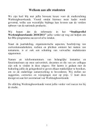
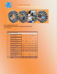
Title BSc final project:Student:Mentor:Co-supervisor:Dynamic modeling <strong>and</strong> validation <strong>of</strong> the <strong>“cooling</strong> <strong>water</strong> <strong>and</strong> <strong>lube</strong><strong>oil”</strong> <strong>system</strong> <strong>of</strong> a 9 <strong>MWe</strong> <strong>Diesel</strong> <strong>engine</strong>Vaseur CyranoDr. Ir. N. R. NannanIr. J. NarainIn Suriname, having a single large power plant based on steam is not possible hence <strong>Diesel</strong><strong>engine</strong>s are applied as the prime movers for “centralized <strong>and</strong> decentralized” power generation.The application <strong>and</strong> operation <strong>of</strong> <strong>Diesel</strong> <strong>engine</strong>s is associated with technological issues whichcan be improved. In order to address such issues it is <strong>of</strong>ten recommended to devise <strong>and</strong>experimentally validate a (dynamic) model for the concerning <strong>system</strong> <strong>of</strong> the <strong>Diesel</strong> <strong>engine</strong>. Withregard to the preceding the main objective <strong>of</strong> this study is:Establishing a dynamic model <strong>of</strong> a <strong>Diesel</strong> <strong>engine</strong> <strong>and</strong> the associated balance-<strong>of</strong>-plant so thestartup behavior can be modeled <strong>and</strong> the predicted/simulated results can be validated. The finalmodel is intended to be used for troubleshooting.However, considering the time available for this study, the specific aim is:Developing a model to simulate the dynamic behavior <strong>of</strong> two sub<strong>system</strong>s comprising theaforementioned balance-<strong>of</strong>-plant, namely the cooling <strong>water</strong> <strong>system</strong> <strong>and</strong> the <strong>lube</strong> oil <strong>system</strong> (seeFigure 1).<strong>lube</strong> oil tank<strong>Diesel</strong><strong>engine</strong>leavingflue gasenteringchargeair<strong>lube</strong> oilpumpLube oil <strong>system</strong>H H HLT stage HT stage<strong>lube</strong> oilCAC CACcoolersplitter 1CAC pump<strong>engine</strong>cooling w aterpumpsplitter 2junction 2junction 1HradiatorCooling <strong>water</strong> <strong>system</strong>enteringcoolingairleavingcoolingairFigure 1 Simplified process flow diagram for the considered sub<strong>system</strong>s (cooling <strong>water</strong> <strong>system</strong><strong>and</strong> <strong>lube</strong> oil <strong>system</strong>) <strong>of</strong> the concerning MAN 18 V32/40 <strong>Diesel</strong> <strong>engine</strong>.
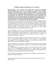
In this regard this graduation project is part <strong>of</strong> a larger research project aimed at developing amodel <strong>of</strong> a 9 <strong>MWe</strong> (approximately 4% <strong>of</strong> the total dem<strong>and</strong> for power in central Suriname) <strong>Diesel</strong>generator set <strong>and</strong> its entire balance-<strong>of</strong>-plant for studying its startup behavior.In order to meet the target, a certain strategy is followed: First an orientation study is done: (i)the working principles <strong>of</strong> the <strong>Diesel</strong> <strong>engine</strong> are studied <strong>and</strong> (ii) the interaction with the balance <strong>of</strong>plant is studied. Thereafter, depending on the purpose <strong>of</strong> the model (see the main objective), (i) atype <strong>of</strong> model is chosen (the model is dynamic <strong>and</strong> modular <strong>and</strong> the distributed propertiesapproach is applied) <strong>and</strong> then (ii) a method for devising a model (which is an iterative procedure)is studied <strong>and</strong> applied:Step 1: Defining the problemStep2:Defining <strong>system</strong>boundaries <strong>and</strong>interconnectingvariablesReal world problemMathematical model:Step 3:Step 4:Step 5:Step 6:Step 7:Development <strong>of</strong> a conceptual modelFormulation <strong>of</strong> model hypothesesDecomposition into sub<strong>system</strong>sFormulation <strong>of</strong> conservation laws <strong>and</strong> othermathematical equationsMathematical simplifications <strong>and</strong>approximationsStep 8:Step 9:Numericalsolution <strong>of</strong> themodelequations,simulationValidation <strong>of</strong> themodel <strong>and</strong> itshypothesesFigure 2 Modeling is an iterative procedure.DocumentationIn this study, the physical-mathematical model obtained after step 7 is implemented in a Matlab-Simulink (computer program) code (step 8). In Figure 3 the information flow diagram <strong>of</strong> the<strong>lube</strong> oil circuit is developed in Matlab simulink.
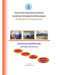
added heat [J]196f_Efl196100341 .15273621p_Epl100000-375132 .90h_Ehl-360092 .34718523320 .4QdTdfldfedf_L_coldf_E_coldpldpedp_L_coldp_E_coldhldhedh_L_coldh_E_cold<strong>Diesel</strong> <strong>engine</strong>Heat exchangerTankPumpfetfltfepflppetpltpepplphethlthephlpomegaepTqpFigure 3 Causality (information flow) diagram <strong>of</strong> the <strong>lube</strong> oil <strong>system</strong> developed inMatlab/Simulink.In this study, the model is validated (step 9) as much as possible analytically, by means <strong>of</strong> Cycle- Tempo (validated computer program) <strong>and</strong> using experimental data received from N. V.Energiebedrijven Suriname (EBS). For example, for the qualitative validation <strong>of</strong> the <strong>lube</strong> oilcircuit (see Figure 3), a step (in fact a fast ramp) is imposed to the added thermal energy by the<strong>Diesel</strong> <strong>engine</strong> (see Figure 4 ). Subsequently, responses <strong>of</strong> for example the entering temperatureT E <strong>of</strong> the medium on the secondary side <strong>of</strong> the heat exchanger are simulated <strong>and</strong> compared withthe expectations (see Figure 5).837 .59.9923 x 106 time [s]210 10 20 30 40 50 60 70 80 90 100Figure 4 Imposed ramp onby the <strong>Diesel</strong> <strong>engine</strong>.
T E[K]3303203100 10 20 30 40 50 60 70 80 90 100time [s]Figure 5 Response <strong>of</strong> T E on the secondary side <strong>of</strong> the heat exchanger. The increase in addedthermal energy results into an increase in the medium temperature. Another effect is the increasein heat transfer by convection on both sides <strong>of</strong> the heat exchanger so that the amount <strong>of</strong> heattransferred by the heat exchanger becomes equal to the added heat by the heat exchanger. Hence,another steady state (higher medium temperature) is reached.Finally, a summary is given <strong>of</strong> the conducted work <strong>and</strong> concluding remarks <strong>and</strong>recommendations for improvement <strong>of</strong> the model are listed.