Series 0i-TD CNC
Series 0i-TD CNC Series 0i-TD CNC
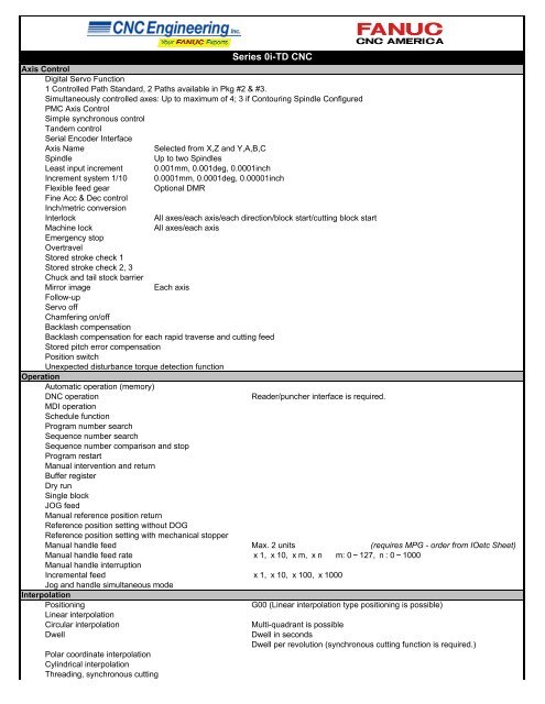
Series 0i-TD CNCAxis ControlDigital Servo Function1 Controlled Path Standard, 2 Paths available in Pkg #2 & #3.Simultaneously controlled axes: Up to maximum of 4; 3 if Contouring Spindle ConfiguredPMC Axis ControlSimple synchronous controlTandem controlSerial Encoder InterfaceAxis NameSelected from X,Z and Y,A,B,CSpindleUp to two SpindlesLeast input increment 0.001mm, 0.001deg, 0.0001inchIncrement system 1/10 0.0001mm, 0.0001deg, 0.00001inchFlexible feed gearOptional DMRFine Acc & Dec controlInch/metric conversionInterlockAll axes/each axis/each direction/block start/cutting block startMachine lockAll axes/each axisEmergency stopOvertravelStored stroke check 1Stored stroke check 2, 3Chuck and tail stock barrierMirror imageEach axisFollow-upServo offChamfering on/offBacklash compensationBacklash compensation for each rapid traverse and cutting feedStored pitch error compensationPosition switchUnexpected disturbance torque detection functionOperationAutomatic operation (memory)DNC operationReader/puncher interface is required.MDI operationSchedule functionProgram number searchSequence number searchSequence number comparison and stopProgram restartManual intervention and returnBuffer registerDry runSingle blockJOG feedManual reference position returnReference position setting without DOGReference position setting with mechanical stopperManual handle feed Max. 2 units (requires MPG - order from IOetc Sheet)Manual handle feed rate x1, x10, xm, xn m: 0~127, n: 0~1000Manual handle interruptionIncremental feedx1, x10, x100, x1000Jog and handle simultaneous modeInterpolationPositioningG00 (Linear interpolation type positioning is possible)Linear interpolationCircular interpolationDwellPolar coordinate interpolationCylindrical interpolationThreading, synchronous cuttingMulti-quadrant is possibleDwell in secondsDwell per revolution (synchronous cutting function is required.)
- Page 2 and 3: Multiple threadingThreading retract
- Page 4 and 5: Help functionRun hour and parts cou
- Page 6: Series 0i-TD CNCOption BoardsEthern
<strong>Series</strong> <strong>0i</strong>-<strong>TD</strong> <strong>CNC</strong>Axis ControlDigital Servo Function1 Controlled Path Standard, 2 Paths available in Pkg #2 & #3.Simultaneously controlled axes: Up to maximum of 4; 3 if Contouring Spindle ConfiguredPMC Axis ControlSimple synchronous controlTandem controlSerial Encoder InterfaceAxis NameSelected from X,Z and Y,A,B,CSpindleUp to two SpindlesLeast input increment 0.001mm, 0.001deg, 0.0001inchIncrement system 1/10 0.0001mm, 0.0001deg, 0.00001inchFlexible feed gearOptional DMRFine Acc & Dec controlInch/metric conversionInterlockAll axes/each axis/each direction/block start/cutting block startMachine lockAll axes/each axisEmergency stopOvertravelStored stroke check 1Stored stroke check 2, 3Chuck and tail stock barrierMirror imageEach axisFollow-upServo offChamfering on/offBacklash compensationBacklash compensation for each rapid traverse and cutting feedStored pitch error compensationPosition switchUnexpected disturbance torque detection functionOperationAutomatic operation (memory)DNC operationReader/puncher interface is required.MDI operationSchedule functionProgram number searchSequence number searchSequence number comparison and stopProgram restartManual intervention and returnBuffer registerDry runSingle blockJOG feedManual reference position returnReference position setting without DOGReference position setting with mechanical stopperManual handle feed Max. 2 units (requires MPG - order from IOetc Sheet)Manual handle feed rate x1, x10, xm, xn m: 0~127, n: 0~1000Manual handle interruptionIncremental feedx1, x10, x100, x1000Jog and handle simultaneous modeInterpolationPositioningG00 (Linear interpolation type positioning is possible)Linear interpolationCircular interpolationDwellPolar coordinate interpolationCylindrical interpolationThreading, synchronous cuttingMulti-quadrant is possibleDwell in secondsDwell per revolution (synchronous cutting function is required.)
Multiple threadingThreading retractContinuous threadingVariable lead threadingPolygon turningSkipHigh-speed skipTorque limit skipReference position return<strong>Series</strong> <strong>0i</strong>-<strong>TD</strong> <strong>CNC</strong>G31Input signal is 1 pointG28Reference position return checkG272nd reference position return3rd/4th reference position returnGeneral purpose retractFeed FunctionRapid traverse rate Max. 240m/min (1μm) Max. 100m/min (0.1μm)Rapid traverse override Fo, 25, 50, 100%Feed per minuteFeed per revolutionTangential speed constant controlCutting feedrate clampAutomatic acceleration/decelerationRapid traverse bell-shaped acceleration/decelerationLinear acceleration/deceleration after cutting feed interpolationFeedrate override 0~254%Jog overrideOverride cancelManual per revolution feedError detectionRapid traverse block overlapExternal decelerationProgrammingTape codeLabel skipParity checkControl in/outOptional block skip (9)Max. programmable dimension0~655.34%EIA RS244/ISO840Horizontal and vertical parityRapid traverse: linear; Cutting feed: exponential±8-digitO4-digitProgram numberExternal memory and sub program calling functionSequence numberAbsolute/incremental programmingDecimal point programming/ pocket calculator type decimal point programmingInput unit 10 time multiplyDiameter/radius programming (X axis)Plane selectionRotary axis designationRotary axis roll-overCoordinate system settingAutomatic coordinate system settingCoordinate system shiftDirect input of coordinate system shiftWorkpiece coordinate system G52~G59Workpiece coordinate system presetDirect input of workpiece origin offset value measuredManual absolute on and offDirect drawing dimension programmingG code systemProgrammable data inputSub program callCustom macro BAddition of custom macro common variablesPattern data inputN5-digitCombined use in the same blockG17, G18, G19A/B/CG104 folds nested#100~#199, #500~#999
<strong>Series</strong> <strong>0i</strong>-<strong>TD</strong> <strong>CNC</strong>Interruption type custom macroCanned cyclesMultiple repetitive cycleMultiple repetitive cycle IIPocket profileCanned cycles for drillingCircular interpolation by R programmingTape format for FANUC <strong>Series</strong> 10/11Auxiliary and Spindle FunctionsAuxiliary functionM8-digit2nd auxiliary functionB8-digitAuxiliary function lockHigh-speed M/S/T/B interfaceMultiple command of auxiliary function 3Spindle speed functionS5-digit, binary outputSpindle serial outputS5-digit, serial outputConstant surface speed controlSpindle override 0~254%Actual spindle speed outputSpindle speed fluctuation detection1st spindle orientation1st spindle output switching function2nd spindle orientation2nd spindle output switching functionSpindle synchronous controlMulti spindle controlSpindle positioningRigid tappingTool Functions and Tool CompensationTool FunctionT7 + 1/T6 + 2 digitsTool offset pairs ±6 digits 64Tool offsetY-axis offsetTool nose radius compensationTool geometry/wear compensationTool life managementTool offset value counter inputAutomatic tool offsetDirect input of tool offset value measuredDirect input of tool offset value measured BPart Program Storage & EditingPart Program Storage 320kB in Pkg #1, 512KB in Pkg #2 & Pkg #3Number of registerable programs 400Part program editingProgram protectBackground editingExtended part program editingPlaybackPassword functionDisplayStatus displayClock functionCurrent position displayProgram displayProgram name 31 charactersParameter setting and displaySelf-diagnosis functionAlarm displayAlarm history displayOperator message history displayOperation history display
Help functionRun hour and parts count displayActual cutting feedrate displayDisplay of spindle speed and T code on all screensDirectory display of floppy cassetteDirectory display and punch for each groupServo setting screenDisplay of hardware and software configurationPeriodic maintenance screenMaintenance information screenTrouble diagnosisSoftware operator's panelSoftware operator's panel general purpose switchEnglish Language Display (as shipped)Data protection keyErase CRT screen displayData Input/Output and CommunicationsI/O Link InterfacePunch Panel with 2m CableReader/Punch Interface 1 (RS-232)<strong>Series</strong> <strong>0i</strong>-<strong>TD</strong> <strong>CNC</strong>Multiple Languages Selectable4 types2nd Channel may be activatedExternal I/O device controlExternal data input: External tool offset External message External machine zero point shiftExternal key inputExternal program inputExternal workpiece number search 9999Expanded external workpiece number searchExternal program number searchMemory card input/outputPower Mate <strong>CNC</strong> managerEmbedded EthernetOtherCD-ROM containing Product Manuals24V Power CableSpare FusesCable ClampsGrounding BarMiscellaneous Solder Connectors1~9999for maintenance
<strong>Series</strong> <strong>0i</strong>-<strong>TD</strong> <strong>CNC</strong>SERIES <strong>0i</strong>-<strong>TD</strong> PACKAGE CHOICESPackage #1 Package #2 Package #34 Axes 4 Axes 4 Axes Pkg #1 uses A02B-0319-B522 Basic Unitand Horizontal LCD/MDI A02B-0319-H144#T8.4" Color LCD/MDI 10.4" Color LCD 10.4" Color LCDw/ Touch Panel Pkg #2 uses A02B-0319-B522 Basic Unit,Basic Unit with 2 slots Basic Unit with 2 slots Basic Unit 2 slots A02B-0319-H140 10.4" LCDand Horizontal MDI A02B-0319-C125.PMC 5K Steps PMC 24K Steps PMC 24K StepsApprox 800m PPS Approx 1280m PPS Approx 1280m PPS Pkg #3 uses A02B-0319-B522 Basic Unit,J682 Touch Panel A02B-0319-H141 10.4" LCD w/ Touch PanelHRV3 Servo Control HRV3 Servo Control HRV3 servo control and Horizontal MDI A02B-0319-C125.PACKAGE DEPENDENT OPTIONSManual Guide i Touch Panel C All <strong>0i</strong>-<strong>TD</strong>'s require at least Version 5.7PROFIBUS DP Master PROFIBUS DP Master of FANUC Ladder III.PROFIBUS DP Slave PROFIBUS DP SlaveTwo Path Control Two Path Controlshading indicates restrictions, see Package Options for detailsORDER FORM<strong>Series</strong> <strong>0i</strong>-<strong>TD</strong> <strong>CNC</strong> Express Package #1 8.4" Color LCD Mount<strong>Series</strong> <strong>0i</strong>-<strong>TD</strong> <strong>CNC</strong> Express Package #2 10.4" Color LCD MountMust choose only one.<strong>Series</strong> <strong>0i</strong>-<strong>TD</strong> <strong>CNC</strong> Express Package #3 10.4" Color LCD w/ Touch ScreenPackage #2 Unique OptionsManual Guide i (S790) (includes Manuals) Cannot order J973, S772Manual Guide i (S786) Multi Path Lathe. Requires 2 Path Control and S790.Package #3 Unique OptionsTouch Panel C (S881) Replaces J682. Cannot order J888,J734,S772,R644. Req's Development Tools.Package #2 & #3 Unique OptionsPROFIBUS DP Master Includes PROFIBUS DP Master Board uses one option slotPROFIBUS DP Slave Includes PROFIBUS DP Slave Board uses one option slotSeparate Type MDI (Standard key) (Vertical)A02B-0319-C126 or equivalentTwo Path Control (S801#2) Req's 4th Servo Axis Interface. Approx 1280m PPS per path.5th Servo Axis Interface6th Servo Axis InterfaceAt least two axes are required per path.7th Servo Axis InterfaceA max of four axes per path are available.8th Servo Axis InterfaceInterference check for each path (J839)Balanced Cutting (J834)Options Compatible with Packages #1, #2 & #33rd Servo Axis Interface4th Servo Axis InterfaceAnalog Spindle Interface (serial spindle interface is standard)Dual Position Feedback (J704)Linear Scale I/F w/ absolute address reference mark (J670). Requires Separate Detector I/F.Bi-Directional Pitch Error Compensation (S656)Manual Handle Retrace (J998)Extended PMC ladder instruction function (R851)Dynamic Graphic Display (J973) Not with Manual Guide i.(enhanced tool path plotting, preview cutting path)Grinding Function A (S682) (includes multi-step skip and canned cycles for grinding)Grinding Function B (S683) incl's Angular Axis Control and Grinding Function A features.
<strong>Series</strong> <strong>0i</strong>-<strong>TD</strong> <strong>CNC</strong>Option BoardsEthernet without Data Server (Uses FOCAS Protocol)uses one option slot(Use Industrial PC Worksheet for PC selection)Data Server Function (req's ATA Flash Card) (Uses FTP for data transfer) uses one option slotCompact Flash Card Kit 1GB (suggested for use with Data Server)Ethernet (Requires Data Server Function) (Uses FOCAS Protocol)Options Available Only with EthernetBasic Operation Package (BOP2) Function (J814)Dual <strong>CNC</strong> Screen Disp (S884) (<strong>CNC</strong> Screen Disp and Enlarged Screen Disp 1024x768, are Basic.)K776 Disk for <strong>CNC</strong> Screen Display - Ethernet. Req'd for <strong>CNC</strong> Screen Disp or Dual <strong>CNC</strong> Screen Disp.Machining Status Monitor Package Function (J870)Application Disk for EthernetLadder Edit Package Function (J820)Manual Guide <strong>0i</strong>Manual Guide <strong>0i</strong> (S772) Not available with Manual Guide i or Touch Panel C.Macro Executor Related Options - require Development Tools. (See Tools Page)Macro Executor (J888) Requires Custom SW size. System SW reserves 96KB.Macro Executor & C-lang Executor (J734) Req's >= 2MB Custom SW. System SW reserves 700KB.FANUC PICTURE Executor (R644) Requires >=3MB Custom SW size. System SW reserves 2MB.Custom SW size 512KB. (J738#512K) J888 1 Path OnlyCustom SW size 1MB. (J738#1M) J888 2 Path OnlyCustom SW size 2MB. (J738#2M) J888 1 Path Only, J734 1 or 2 Paths, not for R644Custom SW size 3MB. (J738#3M) J888 or J734 2 Path Only, R644 OK for 1 PathCustom SW size 4MB. (J738#4M)Custom SW size 5MB. (J738#5M) 2 Path Only Choose the appropriate Custom SW sizeCustom SW size 6MB. (J738#6M) If J888, 2 Path Only to support the ordered Macro Executor.Custom SW size 8MB. (J738#8M) 2 Path OnlyFlash CardCompact Flash Card Kit 128MBI/O unit for <strong>0i</strong>I/O unit for <strong>0i</strong> This is compatible with the DI/DO I/F of I/O card of <strong>Series</strong> <strong>0i</strong>-B. DI/DO : 96/64 pts.See the IOetc page for the available I/O Link signal cables.


