Application Notes - Magnetic Stripe Reader - MagTek
Application Notes - Magnetic Stripe Reader - MagTek
Application Notes - Magnetic Stripe Reader - MagTek
- No tags were found...
You also want an ePaper? Increase the reach of your titles
YUMPU automatically turns print PDFs into web optimized ePapers that Google loves.
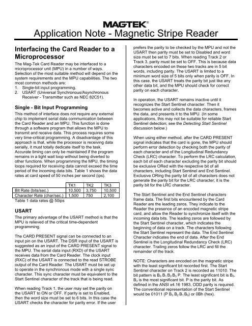
<strong>Application</strong> Note - <strong>Magnetic</strong> <strong>Stripe</strong> <strong>Reader</strong>Interfacing the Card <strong>Reader</strong> to aMicroprocessorThe Mag-Tek Card <strong>Reader</strong> may be interfaced to amicroprocessor unit (MPU) in a number of ways.Selection of the most suitable method will depend on thesystem requirements and the MPU capabilities. The twomost common methods are:1. Single-bit input programming.2. USART (Universal Synchronous/AsynchronousReceiver - Transmitter such as NEC 82C51).Single - Bit Input ProgrammingThis method of interface does not require any externalchip to implement serial data communication betweenthe Card <strong>Reader</strong> and an MPU. This function is donethrough a software program that allows the MPU totransmit and receive data. This process requires somevery time-critical programming. A disadvantage of thisapproach is that, while the processor is receiving dataserially, it must totally dedicate itself to the task.Accurate timing can only be maintained if the programremains in a tight wait loop without being diverted toother functions. When programming the MPU, the timingloops required for receiving data cannot exceed the timeperiod of the incoming data bits. Table 1 shows the datarates at card speed of 50 inches per second (ips).TK1 TK2 TK3Bit Rate (bits/sec.) 10,500 3,750 10,500Character Rate (char/sec.) 1,500 750 2,100Table 1 data rates @ 50ipsUSARTThe primary advantage of the USART method is that theMPU is relieved of the critical time-dependentprogramming.The CARD PRESENT signal can be connected to aninput pin on the USART. The DSR input of the USART issuggested as an input of the CARD PRESENT signal tothe MPU. The serial data input (RXD) of the USARTreceives data from the Card <strong>Reader</strong>. The clock input(RXC) of the USART is connected to the read STROBEoutput of the Card <strong>Reader</strong>. The USART must be set upto operate in the synchronous mode with a single synccharacter. This sync character must be equivalent to theStart Sentinel character of the track that is being read.When reading Track 1, the user may set the parity onthe USART to ON or OFF. If parity is set to Enabled,then the word size must be set to 6 bits. In this case theUSART checks the character for parity error. If the userprefers the parity to be checked by the MPU and not theUSART then parity must be set to Disabled and wordsize must be set to 7 bits. When reading Track 2 orTrack 3, parity must be set to OFF. This is because datacharacters encoded on these two tracks are in 5 bitwords, including parity. The USART is limited to aminimum word size of 5 bits only when parity is OFF. Inthis case, the USART treats the parity bit just like anyother data bit, and the MPU should check for correctparity on each character.In operation, the USART remains inactive until itrecognizes the Start Sentinel character. Then itbecomes active and collects the data characters, framesthe data, and presents it to the MPU. (In someapplications, this may not be suitable for reliable StartSentinel detection; see the Detecting Start Sentineldiscussion below.)When using either method, after the CARD PRESENTsignal indicates that the card is gone, the MPU shouldperform error detection by checking both the parity ofeach character and of the Longitudinal RedundancyCheck (LRC) character. To perform the LRC calculation,each bit of each character excluding the parity bit shouldbe exclusive ORed with the respective bit of allcharacters, including Start Sentinel and End Sentinel.Exclusive ORing the parity bit of all characters does notgenerate the parity bit for the LRC character; it is theparity bit for the LRC character.The Start Sentinel and the End Sentinel charactersframe data. The first bits encountered by the Card<strong>Reader</strong> are the leading zeros. They indicate to the<strong>Reader</strong> the presence of an encoded magnetic stripecard, and allow the <strong>Reader</strong> to synchronize itself with theincoming data bits. The leading zeros are followed bythe Start Sentinel character, which indicates thebeginning of data on a track. The characters followingthe Start Sentinel represent the data. The End SentinelCharacter indicates the end of data. After the EndSentinel is the Longitudinal Redundancy Check (LRC)character. Trailing zeros follow the LRC and fill theremainder of the track.NOTE: Characters are encoded on the magnetic stripewith the least significant bit recorded first. The StartSentinel character on Track 2 is recorded as 11010. Thebit pattern is B 0 B 1 B 2 B 3 P. The least significant bit is B 0 .B 3 is the most significant bit. P is the parity bit. Asdefined in the ANSI x4.16 1983, ODD parity is required.The conventional representation of the Start Sentinelwould be 01011 (P B 3 B 2 B 1 B 0 ) or 0Bh (hex).
Note: For bidirectional reading, a USART cannot beused to identify the Start Sentinel. The USART must beprogrammed to begin capturing data based on the firstbinary 1 that is found. Set the word length to one byte (8bits) and disable parity checking; for track 2, the wordsize should be no more than 5 bits.<strong>Notes</strong>:1. Card Present, Data, and Strobe are negative true logic.2. Card Present goes low after 14-15 head flux reversals.3. Card Present returns to high level approximately 150mS after thelast flux transition.4. Data is valid 1.0µS (min.) before the leading negative edge ofstrobe and remains valid until approximately 1.0µS before thenext STROBE.Detecting Start SentinelIn some cases, random noise on a blank track(especially High Coercivity media) may be detected as aStart Sentinel. If a Start Sentinel is erroneously detectedthen parity and/or LRC checking would undoubtedlyindicate that the track, although blank, actually has anerror on it. For this reason, it is suggested that somenumber of the leading zeros be included in the detectionof Start Sentinel. The location of the Start Sentinel andthe number of zeros required to synchronize the readcircuitry determine the number of detectable zeros priorto the Start Sentinel. In the worst case, there may be nomore than four leading zeros on track 2 and no morethan nine on tracks 1 and 3. In other words, the StartSentinel on track 2 should be considered as a 9-bitvalue: 4 bits of zero and 5 bits of Start Sentinel.Bidirectional ReadingIn many of today’s magnetic stripe card applications,reading the card in both directions is necessary.Programming for bidirectional reading has its ownspecial requirements. First, the data acquired from thereader must be treated in memory as a collection of bits(see note below). Since the direction is not known, theprogram must search the bits looking for the StartSentinel. If the first character is not the Start Sentinel,then you must move to the other end of the memory andbegin searching the bits in reverse order for the StartSentinel. However, if a Start Sentinel is found, it ispossible that the character is LRC. You may check forthis by determining if the next character is the EndSentinel. If the next character is the End Sentinel, thenyou must move to the other end of memory and beginsearching the bits in the reverse order as discussedabove. The important point is to realize that the LRCcould appear to be a false Start Sentinel.If the message does not meet the requirements for acorrect recording (the sentinels, party & LRC) then try tointerpret the message in the other direction. The card isunreadable only after the software has tried bothdirections.Converting Card Data to ASCIIDataThe data transmitted or received by the user’s device isin ASCII. The data encoded on the cards, however, is ina different format called Card Data. All RS-232 Mag-Tekequipment automatically converts transmitted andreceived data from ASCII to Card Data. The procedurefor converting ASCII to Card Data is described bellow.Track 1Card data on Track 1 consists of six binary bits and anodd parity bit for each character. A method forconverting ASCII characters to six-bit Card Data (theparity bit is not included in the calculation) is to subtract20h (hex) from the equivalent 0 parity ASCII character(see Character Conversion Chart). For example, theASCII character that represents the percent sign (%) is25h. Subtract 20h from 25h and the result is 05h, whichrepresents the six-bit portion of the card data code forthe percent sign. An odd parity bit must be added to thesix-bit portion of the character to complete the Card Datacode. A method for converting card data to ASCIIcharacters is to remove the parity bit from the Card Datacode, then add 20h to the remaining six-bit portion of thecharacter. The result will be the 0 parity ASCII character.Track 2 & 3Card data on Track 2 & 3 consists of four binary bits andan odd parity bit for each character. A method forconverting ASCII characters to four-bit Card Data (againthe parity bit is not included in the calculation) is tosubtract 30h from the equivalent ASCII character. Forexample, the ASCII character that represents thenumber 7 is 37h. Subtract 30h from 37h and the result is07h, which represents the four-bit portion of the carddata code for the number 7. An odd parity bit must beadded to the four-bit portion of the character to completethe Card Data code. A method for converting card datato ASCII characters is to remove the parity bit from theCard Data code, then add 30h to the remaining four-bitportion of the character. The result will be the 0 parityASCII character.REGISTERED TO ISO 9001:20001710 Apollo Court, Seal Beach, CA 90740Phone: (562) 546-6400, Help Line (651) 415-6800Fax (562) 546-6301http://www.magtek.comP/N 99875063-4, 4/03 Copyright © 1997-2003, Mag-Tek ® , Inc.


