Measuring/Control Stations DULCOTROL® Waste Water - ProMinent
Measuring/Control Stations DULCOTROL® Waste Water - ProMinent
Measuring/Control Stations DULCOTROL® Waste Water - ProMinent

You also want an ePaper? Increase the reach of your titles
YUMPU automatically turns print PDFs into web optimized ePapers that Google loves.
Corporate InformationCorporate information:General Operating Instructions<strong>Measuring</strong>/<strong>Control</strong> <strong>Stations</strong> DULCOTROL ® <strong>Waste</strong> <strong>Water</strong>© <strong>ProMinent</strong> Dosiertechnik GmbH, 2008<strong>ProMinent</strong> Dosiertechnik GmbHIm Schuhmachergewann 5-1169123 HeidelbergTelephone: +49 (6221) 842-0Fax: +49 (6221) 842-617info@prominent.comwww.prominent.comTechnical changes reserved.Page 2<strong>ProMinent</strong> ®
ContentsPageIdentcode ................................................................................................................ 8General User Information ........................................................................................ 111 Safety Chapter ....................................................................................................... 121.1 Identification of the Notes on Safety ....................................................................... 121.2 General Notes on Safety ......................................................................................... 121.3 Information for Emergencies ................................................................................... 131.4 Proper Use .............................................................................................................. 141.5 Qualification of the Personnel ................................................................................. 142 Storage and Transport .......................................................................................... 143 About this Product ................................................................................................ 153.1 DULCOTROL ® <strong>Waste</strong> <strong>Water</strong> .................................................................................... 154 Overview of <strong>Measuring</strong> <strong>Stations</strong> .......................................................................... 164.1 DULCOTROL ® <strong>Measuring</strong>/<strong>Control</strong> Station with Fitting and In-line Probe DLG III .... 164.2 DULCOTROL ® <strong>Measuring</strong>/<strong>Control</strong> Station with T-Piece Fitting .............................. 174.3 DULCOTROL ® <strong>Measuring</strong>/<strong>Control</strong> Station, Installation Diagram ............................. 185 Mounting / Installation .......................................................................................... 185.1 Mounting (mechanical) ............................................................................................ 185.1.1 <strong>Measuring</strong> Station ................................................................................................... 195.1.2 Accessories ............................................................................................................. 205.2 Installation (hydraulic) .............................................................................................. 215.2.1 DULCOTROL ® <strong>Measuring</strong>/<strong>Control</strong> Station .............................................................. 215.3 Installation of DULCOTROL ® <strong>Measuring</strong>/<strong>Control</strong> Station (electrical) ....................... 225.3.1 <strong>Measuring</strong> Panel ...................................................................................................... 225.3.2 Sample <strong>Water</strong> Pump ............................................................................................... 225.4 Mounting of the Sensors ......................................................................................... 225.5 Hydraulic Test Run after Installation ........................................................................ 225.6 Installation of the Sensor (electrical) ....................................................................... 236 Commissioning of the Sensors ............................................................................ 236.1 Setting of the Flow Meter Switching Point .............................................................. 246.2 Running-In Period ................................................................................................... 247 Device Overview / <strong>Control</strong>s D1C / D2C General ................................................. 25<strong>ProMinent</strong> ® Page 3
Contents8 <strong>Measuring</strong> Parameters........................................................................................... 268.1 <strong>Measuring</strong> Parameter Ozone ................................................................................ 268.1.1 DULCOMETER ® D1C Measured Variable Ozone, Setting and Operation ................ 268.1.2 DULCOTEST ® OZE Ozone Sensor, Commissioning ................................................ 298.1.2.1 DULCOTEST ® OZE Ozone Sensor for Ozone, Assembly ........................................ 298.1.2.2 DULCOTEST ® OZE Ozone Sensor, Electrical Installation ........................................ 308.1.2.3 DULCOTEST ® OZE Ozone Sensor, Running-In........................................................ 308.1.2.4 DULCOTEST ® OZE Ozone Sensor, Calibration ........................................................ 318.1.3 DULCOMETER ® D1C and DULCOTEST ® OZE Ozone Sensor for Ozone,Troubleshooting ....................................................................................................... 338.1.4 DULCOMETER ® D1C Measured Variable Ozon and DULCOTEST ® OZE OzoneSensor for Ozone, Maintenance ............................................................................... 358.2 <strong>Measuring</strong> Parameter H 2O 2................................................................................... 378.2.1 DULCOMETER ® D1C Measured Variable H 2O 2, Setting and Operation .................. 378.2.2 DULCOTEST ® PER Sensor for Hydrogen Peroxide, Commissioning ...................... 408.2.2.1 DULCOTEST ® PER Sensor for Hydrogen Peroxide, Assembly ................................ 408.2.2.2 DULCOTEST ® PER Sensor for Hydrogen Peroxide, Electrical Installation ............. 418.2.2.3 DULCOTEST ® PER Sensor for Hydrogen Peroxide, Running-In .............................. 428.2.2.4 DULCOTEST ® PER Sensor for Hydrogen Peroxide, Calibration .............................. 428.2.3 DULCOMETER ® D1C and DULCOTEST ® PER Sensor for Hydrogen Peroxide,Troubleshooting ....................................................................................................... 448.2.4 DULCOMETER ® D1C Measured Variable H 2O 2and DULCOTEST ® PER Sensorfor Hydrogen Peroxide, Maintenance ....................................................................... 468.3 <strong>Measuring</strong> Parameter Chlorine Dioxide Sensor CDP ........................................ 488.3.1 DULCOMETER ® D1C Measured Variable Chlorine Dioxide Setting and Operation . 488.3.2 DULCOTEST ® CDP Chlorine Dioxide Sensor, Commissioning ................................ 518.3.2.1 DULCOTEST ® CDP Chlorine Dioxide Sensor, Assembly ....................................... 518.3.2.2 DULCOTEST ® CDP Chlorine Dioxide Sensor, Installation ....................................... 528.3.2.3 DULCOTEST ® CDP Chlorine Dioxide Sensor, Running-In ...................................... 528.3.2.4 DULCOTEST ® CDP Chlorine Dioxide Sensor, Calibration ....................................... 538.3.3 DULCOMETER ® D1C and DULCOTEST ® CDP Chlorine Dioxide Sensor,Troubleshooting ....................................................................................................... 558.3.4 DULCOMETER ® D1C Measured Variable Chlordioxid and DULCOTEST ® CDPChlorine Dioxide Sensor, Maintenance ................................................................... 578.4 <strong>Measuring</strong> Parameter Oxygen ............................................................................. 588.4.1 DULCOMETER ® D1C Measured Variable Oxygen, Setting and Operation ............. 588.4.2 DULCOTEST ® Sensor for Dissolved Oxygen, Commissioning ............................... 618.4.2.1 DULCOTEST ® Sensor for Dissolved Oxygen, Assembly ........................................ 618.4.2.2 DULCOTEST ® Sensor for Dissolved Oxygen, Electrical Installation ....................... 618.4.2.3 DULCOTEST ® Sensor for Dissolved Oxygen, Running-In ...................................... 618.4.2.4 DULCOTEST ® Sensor for Dissolved Oxygen, Calibration ....................................... 628.4.3 DULCOMETER ® D1C and DULCOTEST ® Sensor for Dissolved Oxygen,Troubleshooting ....................................................................................................... 638.4.4 DULCOMETER ® D1C Measured Variable Oxygen and DULCOTEST ® Sensor forDissolved Oxygen, Maintenance ............................................................................. 65Page 4<strong>ProMinent</strong> ®
Contents8.5 <strong>Measuring</strong> Parameter Redox/ORP ...................................................................... 668.5.1 DULCOMETER ® D1C Measured Variable Redox/ORP, Setting and Operation ....... 668.5.2 DULCOTEST ® Sensor for Redox/ORP, Commissioning ........................................... 698.5.2.1 DULCOTEST ® Sensor for Redox/ORP, Assembly ................................................... 698.5.2.2 DULCOTEST ® Sensor for Redox/ORP, Electrical Installation ................................... 698.5.2.3 DULCOTEST ® Sensor for Redox/ORP, Running-In ................................................. 698.5.2.4 DULCOTEST ® Sensor for Redox/ORP, Calibration ................................................. 698.5.3 DULCOMETER ® D1C and DULCOTEST ® Sensor for Redox/ORP,Troubleshooting ....................................................................................................... 708.5.4 DULCOMETER ® D1C Measured Variable Redox/ORP and DULCOTEST ®Sensor for Redox/ORP, Maintenance ....................................................................... 718.6 <strong>Measuring</strong> Parameter pH ...................................................................................... 728.6.1 DULCOMETER ® D1C Measured Variable pH, Setting and Operation .................... 728.6.2 DULCOTEST ® PHEP or PHER Sensor for pH, Commissioning .............................. 768.6.2.1 DULCOTEST ® PHEP or PHER Sensor for pH, Assembly ........................................ 768.6.2.2 DULCOTEST ® PHEP or PHER Sensor for pH, Electrical Installation ...................... 768.6.2.3 DULCOTEST ® PHEP or PHER Sensor for pH, Running-In ...................................... 768.6.2.4 DULCOTEST ® PHEP or PHER Sensor for pH, Calibration ....................................... 768.6.3 DULCOMETER ® D1C and DULCOTEST ® PHEP or PHER Sensor for pH,Troubleshooting ....................................................................................................... 788.6.4 DULCOMETER ® D1C Measured Variable pH and DULCOTEST ® PHEP or PHERSensor for pH, Maintenance ................................................................................... 798.7 <strong>Measuring</strong> Parameter Inductive Conductivity ..................................................... 808.7.1 DULCOMETER ® D1C Measured Variable Inductive Conductivity,Setting and Operation .............................................................................................. 808.7.2 DULCOTEST ® ICT 2 Inductive Conductivity Sensor, Commissioning .................... 838.7.2.1 DULCOTEST ® ICT 2 Inductive Conductivity Sensor, Assembly .............................. 838.7.2.2 DULCOTEST ® ICT 2 Inductive Conductivity Sensor, Electrical Installation ............ 838.7.2.3 DULCOTEST ® ICT 2 Inductive Conductivity Sensor, Running-In ............................ 848.7.2.4 DULCOTEST ® ICT 2 Inductive Conductivity Sensor, Calibration ............................ 848.7.3 DULCOMETER ® D1C Measured Variable Inductive Conductivity andDULCOTEST ® ICT 2 Inductive Conductivity Sensor, Troubleshooting .................... 898.7.4 DULCOMETER ® D1C Measured Variable Inductive Conductivity andDULCOTEST ® ICT 2 Inductive Conductivity Sensor, Maintenance ......................... 898.8 <strong>Measuring</strong> Parameter Temperature ..................................................................... 908.8.1 DULCOMETER ® D1C Measured Variable Temperature, Setting and Operation ...... 908.8.2 Temperature Sensor PT 100 SE, Commissioning ................................................... 938.8.2.1 Temperature Sensor PT 100 SE, Assembly ............................................................. 938.8.2.2 Temperature Sensor PT 100 SE, Electrical Installation ........................................... 938.8.2.3 Temperature Sensor PT 100 SE, Running-In ........................................................... 938.8.2.4 Temperature Sensor PT 100 SE, Calibration ........................................................... 938.8.3 DULCOMETER ® D1C Measured Variable Temperature andTemperature Sensor PT 100 SE, Troubleshooting ................................................... 948.8.4 DULCOMETER ® D1C Measured Variable Temperature andTemperature Sensor PT 100 SE, Maintenance ........................................................ 94<strong>ProMinent</strong> ® Page 5
Contents8.9 <strong>Measuring</strong> Parameter Total Chlorine .................................................................... 958.9.1 DULCOMETER ® D1C Measured Variable Chlorine, Setting and Operation ............ 958.9.2 DULCOTEST ® CTE Sensor for Total Chlorine, Commissioning .............................. 988.9.2.1 DULCOTEST CTE Sensor for Total Chlorine, Assembly ......................................... 988.9.2.2 DULCOTEST ® CTE Sensor for Total Chlorine, Electrical Installation ...................... 998.9.2.3 DULCOTEST ® CTE Sensor for Total Chlorine, Running-In ...................................... 1008.9.2.4 DULCOTEST ® CTE Sensor for Total Chlorine, Calibration ...................................... 1008.9.3 DULCOMETER ® D1C and DULCOTEST ® CTE Sensor for Total Chlorine,Troubleshooting ........................................................................................................ 1028.9.4 DULCOMETER ® D1C Measured Variable Chlorine and DULCOTEST ® CTESensor for Total Chlorine, Maintenance .................................................................. 1058.10 <strong>Measuring</strong> Parameter pH/Chlorine ...................................................................... 1068.10.1 DULCOMETER ® D2C Measured Variable pH/Chlorine, Setting and Operation ...... 1068.10.2 DULCOTEST ® CTE Sensor for Total Chlorine and DULCOTEST ® SensorPHEP or PHER for pH, Commissioning .................................................................. 1118.10.2.1 DULCOTEST ® CTE Sensor for Total Chlorine and DULCOTEST ® SensorPHEP or PHER for pH, Assembly ............................................................................ 1118.10.2.2 DULCOTEST ® CTE Sensor for Total Chlorine and DULCOTEST ® SensorPHEP or PHER for pH, Electrical Installation .......................................................... 1128.10.2.3 DULCOTEST ® CTE Sensor for Total Chlorine and DULCOTEST ® SensorPHEP or PHER for pH, Running-In .......................................................................... 1138.10.2.4 DULCOTEST ® CTE Sensor for Total Chlorine and DULCOTEST ® SensorPHEP or PHER for pH, Calibration .......................................................................... 1148.10.3 DULCOMETER ® D2C, DULCOTEST ® CTE Sensors for Total Chlorine andDULCOTEST ® Sensors PHEP or PHER for pH, Troubleshooting ............................ 1178.10.4 DULCOMETER ® D2C Measured Variable Chlorine, DULCOTEST ® CTESensor for Total Chlorine and DULCOTEST ® Sensor PHEP or PHER for pH,Maintenance ............................................................................................................ 1188.11 <strong>Measuring</strong> Parameter pH/Redox (ORP) .............................................................. 1198.11.1 DULCOMETER ® D2C Measured Variable pH/Redox (ORP), Setting and Operation............................................................................................................................1198.11.2 DULCOTEST ® Redox (ORP) Sensor RHER-Pt-SE and DULCOTEST ® SensorPHEP or PHER for pH, Commissioning .................................................................. 1248.11.2.1 DULCOTEST ® Redox (ORP) Sensor RHER-Pt-SE and DULCOTEST ® SensorPHEP or PHER for pH, Assembly ............................................................................ 1248.11.2.2 DULCOTEST ® Redox (ORP) Sensor RHER-Pt-SE and DULCOTEST ® SensorPHEP or PHER for pH, Electrical Installation ........................................................... 1248.11.2.3 DULCOTEST ® Redox (ORP) Sensor RHER-Pt-SE and DULCOTEST ® SensorPHEP or PHER for pH, Running-In........................................................................... 1258.11.2.4 DULCOTEST ® Redox (ORP) Sensor RHER-Pt-SE and DULCOTEST ® SensorPHEP or PHER for pH, Calibration ........................................................................... 1258.11.3 DULCOMETER ® D2C, DULCOTEST ® Redox (ORP) Sensor RHER-Pt-SE andDULCOTEST ® Sensor PHEP or PHER for pH, Troubleshooting ............................. 1278.11.4 DULCOMETER ® D2C Measured Variable pH, Redox (ORP), DULCOTEST ® Redox(ORP) Sensor RHER-Pt-SE and DULCOTEST ® Sensor PHEP or PHER for pH,Maintenance ............................................................................................................ 128Page 6<strong>ProMinent</strong> ®
Contents8.12 <strong>Measuring</strong> Parameter pH/Chlorine Dioxide ........................................................ 1298.12.1 DULCOMETER ® D2C Measured Variable pH/Chlorine Dioxide, Setting andOperation .................................................................................................................. 1298.12.2 DULCOTEST ® CDE Chlorine Dioxide Sensor and DULCOTEST ® Sensor PHEP orPHER for pH, Commissioning ................................................................................. 1348.12.2.1 DULCOTEST ® CDE Chlorine Dioxide Sensor and DULCOTEST ® Sensor PHEP orPHER for pH, Assembly .......................................................................................... 1348.12.2.2 DULCOTEST ® CDE Sensor and DULCOTEST ® Sensor PHEP or PHER for pH,Electrical Installation ................................................................................................. 1358.12.2.3 DULCOTEST ® CDE Chlorine Dioxide Sensor and DULCOTEST ® Sensor PHEP orPHER for pH, Running-In ........................................................................................ 1368.12.2.4 DULCOTEST ® CDE Chlorine Dioxide Sensor and DULCOTEST ® Sensor PHEP orPHER for pH, Calibration ......................................................................................... 1368.12.3 DULCOMETER ® D2C, DULCOTEST ® CDE Chlorine Dioxide Sensor andDULCOTEST ® Sensor PHEP or PHER for pH, Troubleshooting ............................. 1398.12.4 DULCOMETER ® D2C Measured Variable pH/Chlorine Dioxide,DULCOTEST ® CDE Chlorine Dioxide Sensor and DULCOTEST ® Sensor PHEP orPHER for pH, Maintenance ..................................................................................... 1408.13 <strong>Measuring</strong> Parameter pH/pH ............................................................................... 1418.13.1 DULCOMETER ® D2C Measured Variable pH/pH, Setting and Operation ............... 1418.13.2 DULCOTEST ® Sensor PHEP or PHER for pH, Commissioning .............................. 1468.13.2.1 DULCOTEST ® Sensor PHEP or PHER for pH, Assembly ....................................... 1468.13.2.2 DULCOTEST ® Sensor PHEP or PHER for pH, Electrical Installation .................... 1468.13.2.3 DULCOTEST ® Sensor PHEP or PHER for pH, Running-In ..................................... 1468.13.2.4 DULCOTEST ® Sensor PHEP or PHER for pH, Calibration ...................................... 1478.13.3 DULCOMETER ® D2C, DULCOTEST ® Sensor PHEP or PHER for pH,Troubleshooting ....................................................................................................... 1488.13.4 DULCOMETER ® D2C Measured Variable pH/pH, DULCOTEST ® Sensor PHEP orPHER for pH, Maintenance ..................................................................................... 1499 Settings of the <strong>Control</strong>lers D1C/D2C Deviating from the Data in theD1C/D2C Operating Instructions (to be observed during repairs) ................... 1509.1 Deviating <strong>Measuring</strong> Ranges.................................................................................... 1509.2 Setting of the Pause Contact for Flow Monitoring .................................................. 15110 Maintenance .......................................................................................................... 15211 Troubleshooting ...................................................................................................... 15312 Decommissioning and Disposal .......................................................................... 15412.1 Temporary or Long-Term Decommissioning ............................................................ 15412.2 Final Decommissioning ............................................................................................ 15413 Replacement Parts ................................................................................................ 15414 List of Further Applicable Documents .................................................................. 15515 EC Declaration of Conformity .............................................................................. 157<strong>ProMinent</strong> ® Page 7
IdentcodeIdentcode <strong>Measuring</strong>/<strong>Control</strong> Station DULCOTROL ® <strong>Waste</strong> <strong>Water</strong> –One Measured VariableWWCA Measured variableG000 Total chlorine (free+combined chlorine or chlorine measurement for pH value > 8.0 ) for "water to be measured" 1, 2P000 pHR000 ORP for "water to be measured" 1, 2, 3L000 ConductivityD000 Chlorine dioxide (with temperature as correction variable) for "water to be measured": 1,2Z000 Ozone for "water to be measured": 1,2H000 Hydrogen peroxide for "water to be measured": 1,2F000 Fluoride for "water to be measured" 1, 2, 4 (pH min. = 5.5, pH max. = 8.5)T000 Temperature for "water to be measured": 1, 2, 3<strong>Water</strong> to be measured1 Clear water2 <strong>Water</strong> with solid fraction, turbid3 <strong>Water</strong> with solid fraction, muddy (sensor directly within pipe, without filter4 <strong>Water</strong> with fluoride and pH < 7Usage category0 All measured variables only measurable9 All measured variables two-way controllablePower supplyA 230 V, 50/60 HzC 115 V, 50/60 HzSensor equipment0 With sensors1 Without sensorsVersion0 With <strong>ProMinent</strong> logoSample water treatments0 None1 With filterAccessories0 None2 With heat exchanger3 With sample water pump6 With heat exchanger and sample water pumpLanguageDE GermanEN EnglishFR FrenchIT ItalianNL DutchES Spanish, not for H000PL Polish, not for H000SV Swedish, not for H000HU Hungarian, not for H000PT Portuguese, not for H000CS Czech, not for H000Approvals1 CEPage 8<strong>ProMinent</strong> ®
Safety Chapter1 Safety Chapter1.1 Identification of the Notes on SafetyThe following terms are used in the present operating instructions to indicate the various severitylevels of the danger:DANGERCharacterizes a possibly hazardous situation. There is a danger of death or serious injuriesif these notes are disregarded.WARNINGCharacterizes a possibly hazardous situation. Your life is in danger and there is a danger ofserious injury or death if these notes are disregarded!CAUTIONCharacterizes a possibly hazardous situation. There is a danger of slight or minor injury ordamage to property if these notes are disregarded.NOTEA note provides important notes for the correct functioning of the unit or is to facilitateyour work.The following warning signs are used in the present operating instructions to indicate differenttypes of the danger:Warning of danger areaWarning of hazardous electrical voltageWarning of caustic substancesWarning of hot surfacesWarning of unexpected start1.2 General Notes on SafetyWARNING• Live parts!• Disconnect from mains plug before opening the housing.• De-energise damaged, defective or manipulated units by disconnecting the mains plug.WARNING• Hot surfaces!• Risk of burning at the surfaces of the measuring station.• For sample water > 55 °C, a temperature monitor with solenoid valve has to be installedto protect the DULCOTROL ® measuring/control station. The temperature monitor is notincluded in the scope of delivery and must be installed by the customer.• Suitable measures must be taken to prevent that nobody gets into contact with hotsurfaces.Page 12<strong>ProMinent</strong> ®
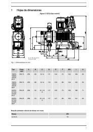
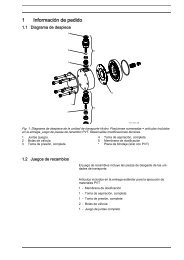
Mounting/InstallationCAUTION• Metering media may be metered in excess.• If the float of the flow module gets stuck because of contaminations, the DULCOTROL ®measuring/control station may meter in excess!• Install a filter, depending on the type and composition of the sample water.• If the circulating pump does not deliver, the DULCOTROL ® measuring/control stationmay meter in excess!• Interlock the control via the potential-free contact of the circulating pump. If the cir culating pump is “OFF”, the DULCOTROL ® measuring/control station goes to “PAUSE” viathe pause input of the controller.• Alternatively, the metering pumps can be switched such that they only work togetherwith the circulating pumps.5.1.1 <strong>Measuring</strong> StationThe mounting height should be selected such that:• the LCD panel of the control is well readable• the cover of the controller can still be parked in “park position” (145 mm)• there is still enough space below the in-line probe to carry out maintenance work (100 mm)• there is enough space for the mounting of accessories beyond the panelThe following drilling dimensions are to be observed in accordance with the panel size:Number of measured variables 1 2 3A 595 695 1000B 745 695 800C 555 655 960D 705 655 760<strong>ProMinent</strong> ® Page 19
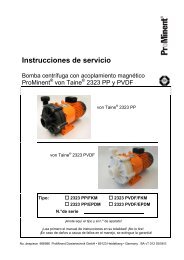
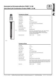
Mounting/Installation Install the DULCOTROL ® measuring/control station as close as possible to the meteringstation using hanger screws.10 mm1 23 41 Plugs (type depending on the surface and according to the plug manufacturer’s specifications)2 Hanger screw3 U-washer4 Hexagon nut5.1.2 AccessoriesWith accessories: From the hydraulical point of view, install supplied accessories such as heatexchanger, sample water pump, or filter upstream of the DULCOTROL ® measuring/controlstation, observing the respective operating instructions.1 Sample water pump2 Heat exchanger (water/water)3 Filter4 Temperature monitor with shut-off valveNot included in delivery scope, to be installed by the customer at media temperatures > 55 °CPage 20<strong>ProMinent</strong> ®
Mounting/Installation5.2 Installation (hydraulic)CAUTION• Observe the maximum permissible operating parameters of the entire installation of theDULCOTROL ® measuring/control station (e.g. pressure, temperature, flow rate)!• Observe the lowest maximum permissible operating parameters of the component partsof the DULCOTROL ® measuring/control station and the installed sensors (and theiroperating instructions)!• Please also read the operating instructions of the controllers and fittings and any otherexisting assemblies such as sensors, sample water pump … !• Ensure a correct flow direction of the sample water.• The maximum operating pressure (1 bar) may not be exceeded.• A pressure reducer must be installed.• Hazards from media under pressure.• Before starting work at the hydraulical part of the DULCOTROL ® measuring/controlstation, this part is to be depressurised in a controlled way using the sampling valve.• Wear safety goggles.FittingsThe bypass fitting (in-line probe) used depends in particular on the sample water, sometimes alsoon the measured variable or the combination of the measured variables. For all clear, turbid orfluoride-containing water, the type DLG III with flow monitoring, and for muddy water, a T-piece isalways used.Particularities• for fluoride, the fitting DLG IV is used• for the conductivity with ICT 2, a milk pipe connection for direct adaptation to the process isused• for dissolved oxygen, a T-piece adapter is usedHydraulic connection, pipingThe sample water is hydraulically connected using a 8x5 mm hose connection for the fittingDLG III/IV or a pipe DN 25 if a T-piece is used as fitting. Shut-off ball valves are installedupstream and downstream of the bypass fitting. Upstream of the bypass fitting, the optionallyavailable sample water filter will be positioned. The bypass fittings include a sampling valve.For an equipotential bonding circuit, a metal pin is integrated in the bypass fittings (see operatinginstructions DULCOMETER ® D1C, Part 1).5.2.1 DULCOTROL ® <strong>Measuring</strong>/<strong>Control</strong> Station Connect the in-line probe or fitting to the sample water (see operating instructions of thein-line probe or documentation of the fitting).<strong>ProMinent</strong> ® Page 21
Mounting/Installation5.3 Installation of DULCOTROL ® <strong>Measuring</strong>/<strong>Control</strong> Station (electrical)WARNING• Live parts!• Disconnect from mains plug before opening the housing.• De-energise damaged, defective or manipulated units by disconnecting the mains plug.• The electrical installation of the electrical assemblies may only be performed by aqualified electrician!• The controller may only be opened by a qualified electrician!• With only one controller: Install a mains switch to be able to quickly disconnect from themains supply in case of emergency! For stations with two or more controllers, theswitch is installed at the terminal box.CAUTION• Please also read the operating instructions of the controllers and fittings and any otherexisting assemblies such as sensors, sample water pump … !5.3.1 <strong>Measuring</strong> Panel Install a mains cable at the terminal box or at the controller in case of only one controller. Electrically install the flow meter (cables are pre-installed at the controller).5.3.2 Sample <strong>Water</strong> Pump With terminal box: Connect the sample water pump to the terminal box in accordance with theterminal diagram. Without terminal box: Connect the sample water pump to the supply voltage as described inits operating instructions.5.4 Mounting of the SensorsDepending on the Identcode (Identcode feature “Sensor assembly”), some sensors will bedelivered already installed in the fitting. If no sensors are installed, the holes in the fitting aretightly sealed.The following sensors are not delivered as installed because of their sensitivity but enclosed inthe original packaging of the DULCOTROL ® measuring/control station.• All pH/ORP sensors• All amperometric sensors• The oxygen sensor DO 1 will be installed, the sensor module will be separately enclosed.The sensors for oxygen, conductivity, and temperature are pre-installed.Before installing the sensors, the respective blanking plugs are to be removed from theDULCOTROL ® measuring/control station and the respective sensors are then to be installed. Theinstallation of the sensors is described in the respective chapter for the measured variable.5.5 Hydraulic Test Run after InstallationHaving completed the installation, a hydraulic test run of the DULCOTROL ® measuring/controlstation is to be performed.• The sampling valve must be closed! Otherwise, sample water may leak!• Check all screw fittings before the first commissioning!• Open the shut-off ball valve on the inlet and outlet side.• The station must be hydraulically leak-proof. No liquids may escape.Should liquid escape, the cause is to be identified and remedied.Page 22<strong>ProMinent</strong> ®
Mounting/Installation / Commissioning of the Sensors5.6 Installation of the Sensor (electrical)The cable ends of the connecting lines are identified by measured variables. The identification ismade with cable markers at the cable end. These markers are assigned to the measured variablesas follows:Measured variable <strong>Control</strong>ler Sensor type CableidentificationidentificationpH pH PHE PORP Redox/ORP RHE RConductivity, inductive Conductivity ICT Pre-installedTotal chlorine CL CLE CLChlorine dioxide CLO 2CDE, CDP CDOzone O 3OZE OZHydrogen peroxide H 2O 2PER PEDissolved oxygen O 2DO1 Pre-installedTemperature Temperature PT PTFluoride Fluoride FLE6 Commissioning of the SensorsWARNING• Hazardous substances!• Hazards from contact, inhalation or other contamination with/by substances or media!• Observe the safety data sheet of the used substance/media.• The operator of the DULCOTROL ® measuring/control station is responsible for the factthat the safety data sheets are available and up-to-date.CAUTION• The sampling valve must be closed! Otherwise, sample water may leak!• The sample water may not contain any airlocks to guarantee reliable measuring andcontrolling!Should air be contained in the sample water due to processes, the air is to be separatedwith suitable technical means.• Please also read the operating instructions of the controllers and fittings and any otherexisting assemblies such as sensors, sample water pump … !maximum permissible operating pressure: 1 bar at max. 55 °CPreparation Retighten all screw fittings and check for leakages. Check the positions of all shut-off valves. The position of the shut-off valves must guaranteethat the DULCOTROL ® measuring/control station is leak-proof and that the sample waterflows. Connect the mains plugs to their corresponding socket-outlets and switch on the power.<strong>ProMinent</strong> ® Page 23
Commissioning of the Sensors6.1 Setting of the Flow Meter Switching Point Reduce the flow rate for the test - the alarm device must engage. Check the screw fitting for leakages.For in-line probe DLG III:Objective: Flow rate reduction is to switch – “Pause” at controller given closed input Set the flow rate at the ball valve. Setting value: 40 l/h Test value: 30 to 60 l/h (read at the upper edge of the float) Loosen the flow rate sensor. Move the flow rate sensor in the rail from the top to the bottom until the controller goes to“Pause”. Move the flow rate sensor to the top until “Pause” at the controller is just cancelled. Secure the flow rate sensor. Reduce the flow rate for the test - the controller must go to “Pause”.6.2 Running-In PeriodA running-in period is to be observed for all amperometric sensors. Depending on the sensor, thismay vary between 1 hour and 24 hours. The respective sensor, electrically connected, must bepositioned in the sample water to be measured in a system with flow. This sample water mustalready contain the measured variable in the quality and quantity sufficient for the process.Running-in of the sensors is described in the respective chapter for the measured variable.Page 24<strong>ProMinent</strong> ®
Device Overview / <strong>Control</strong>s D1C / D2C General7 Device Overview / <strong>Control</strong>s D1C / D2C General12XXXXXX®3847DULCOMETER ®6STOPSTART51 Respective measured variable2 Display5UP buttonTo increase a displayed numerical valueand to change variables (flashing display)768BRANCH BACK buttonBack to permanent display or to start ofrelevant setting menu.DOWN buttonTo decrease a displayed numerical valueand to change variables (flashing display).CHANGE buttonTo change over within a menu level andto change from one variable to anotherwithin a menu point.34STOPSTARTSTART/STOP buttonStart/stop of control and metering function.ENTER buttonTo accept, confirm or save a displayedvalue or status. For alarm acknowledgement.<strong>ProMinent</strong> ® Page 25
Ozone8 <strong>Measuring</strong> Parameters8.1 <strong>Measuring</strong> Parameter Ozone8.1.1 DULCOMETER ® D1C Measured Variable Ozone, Setting and OperationDisplay SymbolsThe display of the DULCOMETER ® D1C measured variable ozone controller uses the followingsymbols:Description Comment SymbolLimit value transgressionRelay 1, upperRelay 1, lowerRelay 2, upperRelay 2, lowerMetering pump 1 (ozone)<strong>Control</strong> off<strong>Control</strong> onMetering pump 2 (De-ozone)<strong>Control</strong> off<strong>Control</strong> onSolenoid valve 1 (ozone)<strong>Control</strong> off<strong>Control</strong> onSolenoid valve 2 (De-ozone)<strong>Control</strong> off<strong>Control</strong> onServomotor<strong>Control</strong>, open relayleftleftleftleftleftleftSymbolSymbolSymbolSymbolSymbolSymbolSymbolSymbolSymbolSymbolSymbolSymbolrightrightrightrightrightright<strong>Control</strong>, close relayWithout controlPosition feedbackStop button pressedThickness of barincreases from left to rightduring openingManual meteringFaultPage 26<strong>ProMinent</strong> ®
OzoneOperationPermanentdisplay 1Permanentdisplay 2The various menus are selected withthe CHANGE buttonThe menu is started withthe ENTER buttonBRANCH BACK to permanent displayor to relevant setting menuCalibrationmenuCalibration notesVariousSetting menusAccess codeAccess code, correctParametersettingD1C2-O3-007-GBNOTEAccess to the setting menus can be barred with the access code!The number and scope of setting menus is dependent on the device version!If the access code is selected correctly in a setting menu, then the following setting menusare also accessible!If within a period of 10 minutes no button is pushed, the unit automatically branches backfrom the calibrating menu or a setting menu to the permanent display 1!BRANCH BACK withoutsaving settingBRANCH BACK tostart of settingText 1Text Selection 2 1Selection 2CHANGE from selection to selectionChange numbers orsettings of selectionVariables flashText 1Text Selection 2 1Selection 2ENTER and save setting,continue to next menuD1C2-O3-008-GB<strong>ProMinent</strong> ® Page 27
OzoneRestricted Operating Menu / LayoutThe restricted operating menu permits simple operation of the most important parameters. Thefollowing overview shows the settings which can be selected.ppm0.20Permanent display 1mea. val. 0.20 ppmfd. fwd.: 70 %reg. val.: 59 %w= 0.20 ppmPermanent display 2only with control(w = setpoint)Positive values of setting variable: OzoneNegative values of setting variable: De-ozone(ozone destruction)calibration O3zero p.: 4.00 mAslope:6.00 mA/ppmcalibration O3DPD-value:0.20 ppmcalibration O3zero p.: 4.00 mAslope:6.75 mA/ppmNumber and scope ofsetting menus isdependent on the devicelimitssetting ?limit 20.50 ppmlimit 10.10 ppmupperlowerAccess to settingmenus can be blockedwith access codecontrolsettings ?Only with controlSetting incompleteoperatingmenucontrolregulated value:positive O3negative de-O3controlnormalcurrent regulat.value: 30 %orcontrolwith dead zonecurrent regulat.value: 30 %orcontrolmanualcurrent regulat.value: 30 %For normal controlsetpoint0.20 ppm<strong>Control</strong> with dead zonesetpoint 2 upper0.20 ppmsetpoint 1 lower0.20 ppm<strong>Control</strong> manualmanual dosing15 %regulated rangeProportional controlctrl. parameterxp = 10 %PID controlctrl. parameterxp = 10 %Ti = offTd = offgeneral settinginformationident-code: D1CADxZxxxxxxxxxxsoftware versionD1C-B1 FW-5.00alarm relayactiveaccess c.: 5000operating menu:= english= restrictedD1C2-O3-010-GBPage 28<strong>ProMinent</strong> ®
Ozone8.1.2 DULCOTEST ® OZE Ozone Sensor, Commissioning8.1.2.1 DULCOTEST ® OZE Ozone Sensor for Ozone, AssemblyPouring electrolyteAssemblyCAUTION• When handling ozone-containing water and solutions wear appropriate safety gogglesand protective clothing!• In case of eye contact with the electrolyte, rinse immediately with a lot of clean waterfor at least 10 min.! In case of eye irritation, contact an eye specialist!• Do not swallow the electrolyte! Drink a lot of water. Trigger vomiting. Seek medicaladvice in case of indisposition!• Protect yourself and your clothing against contact with the electrolyte (acid!) by suitableprotective equipment!• The skin might be chemically burnt or the clothing might be damaged! Rinse immediatelywith a lot of cold water.IMPORTANT• Do not touch, damage or bring into contact with greasy substances the membrane atthe bottom of the membrane cap and the electrodes at the bottom of the electrodeshaft! The sensor will then no longer function accurately. Replace the membrane cap bya new one or return the sensor for cleaning of the electrodes.• The electrolyte should not be kept in excess of 2 years! (For date of expiry, see label) Remove the red cap from the spout and cut the spout at the marked position to open thespout channel. Remove the protective membrane cover and unscrew the membrane cap from the electrodeshaft. Rinse the membrane cap and the electrode with some of the electrolyte. Fill the membrane cap up to the brim with the electrolyte. Slightly tap the membrane cap onto an even surface to remove any air bubbles.Assembling themembrane cap Place the electrode shaft vertically on the filled membrane cap and turn until the thread islocked. Turn the electrode shaft such that the vent hole is positioned to the top. Slowly screw in the membrane cap fingertight by hand up to the stop. The excessive electrolyteflows out through the vent hole when screwing together the parts. Rinse the leaked electrolyte from the sensor and your fingers under running water. No air should be trapped in the membrane cap and the electrolyte. If air is trapped, repeat theabove described steps.Assembling sensorIMPORTANT• Depressurise the in-line probe before installing the sensor!• Insert or remove the sensor only slowly into or from the in-line probe! Otherwise themembrane may be damaged!• The membrane may not come into contact with the flow plug of the in-line probe!• Ensure that the tensioning ring of the sensor is positioned within the in-line probe afterinstallation! Otherwise, the sensor might be ejected from the in-line probe due to thewater pressure.• After commissioning, the sensor must always be kept wet – e.g. the in-line probe maynever run dry! Install the sensor as described in the operating instructions of the in-line probe.<strong>ProMinent</strong> ® Page 29
Ozone8.1.2.2 DULCOTEST ® OZE Ozone Sensor, Electrical InstallationIMPORTANT• Do not switch off the measuring system during interval operation!If required, switch on metering unit time-delayed!• In case of sensor failure, an incorrect measuring value may be present at the input ofthe control unit. Design the electrical installation such that it will not result in anyuncontrolled metering and consequential damages!When connecting to a<strong>ProMinent</strong> ® devices When connecting to <strong>ProMinent</strong> control units (e.g. DULCOMETER ® D1C), the safety requirementson the interface are automatically met.The OZE 3-mA is a sensor with a passive 4-20 mA two-wire interface, i.e. the power is suppliedexternally, e.g. via the control unit.Electrical connectionto sensorElectrical Installation Turn the adapter of the sensor one quarter turn anti-clockwise and pull off (bayonet mount). Loosen the clamping screw of the M12 screw fitting and feed through the measuring line fromthe control unit. Strip the cable ends and connect to the 2-wire connector: 1 = Plus, 2 = Minus.5 cm1 2 Position approx. 5 cm of the measuring line in the sensor and tighten the clamping screw ofthe M12 screw fitting. Fully insert the sensor into the housing and gently turn clockwise up to the stop. Ensure thatthe lugs of the bayonet mount do not break.8.1.2.3 DULCOTEST ® OZE Ozone Sensor, Running-InIMPORTANT• The sensor may not be used in surfactant-containing water or solutions!• Do not switch off the measuring system during interval operation!After any operation without ozone, running-in periods are to be reckoned with.If required, switch on metering unit time-delayed!If no ozone is metered for a longer period of time, the sensor must be disconnectedfrom the power supply and stored dry.Running-In PeriodThe sensor requires a certain running-in period to be able to provide a stable reading.Initial commissioning:2 - 6 hRecommissioning:1 - 3 hReplacement of diaphragm/electrolyte: approx. 0.5 hPage 30<strong>ProMinent</strong> ®
Ozone8.1.2.4 DULCOTEST ® OZE Ozone Sensor, CalibrationAfter expiry of the running-in period, the sensor can be calibrated.IMPORTANT• A slope calibration must be carried out after having replaced a diaphragm cap orelectrolyte!• For a perfect functioning of the sensor, the slope calibration must be repeated in regularintervals! For swimming pools, a calibration of the sensor every 3-4 weeks is sufficient.• Avoid incorrect metering because of airlocks in the sample water! Air bubbles stickingto the diaphragm of the sensor might cause a low measuring value and thus mightresult in incorrect metering.• Observe the valid national regulations for calibration intervals!Preconditions • Constant flow at the in-line probe• Operating pressure of max. 1 bar maintained• Constant temperature of the sample water• Identical temperatures of sample water and sensor (wait for approx. 15 min.)• Constant pH valueZero Point CalibrationIf the sensor is operated at a <strong>ProMinent</strong> control unit, a zero point calibration is normally notrequired. Perform a zero point calibration if you use the sensor at the lower measuring range limit.Preconditions • The sensor has been run-in• Constant flow at the in-line probe Dip the sensor in a bucket with clean, ozone-free tap water. Stir with the sensor until the reading at the control unit has been stable for 5 min. Calibrate the control unit to zero according to its operating instructions. Reinstall the sensor into the in-line probe (DGM; DLG).Slope TestDetermine the ozone content of the sample water using a suitable measuring tool (e.g. DPD 4).Set the determined value at the control unit according to the unit’s operating instructions.Repeat the calibration the next day!NOTECalibration at increased temperatureBecause ozone is only physically solved in water, it quickly outgasses from the medium atincreased temperatures (> 30 °C). The DPD measurement must thus be performed quickly.After sample-taking, the reagents should be added within 1 minute. In this case, the reddye is to be directly generated at the sampling site by adding reagents and then themeasurement is to be performed in the laboratory as quickly as possible.<strong>ProMinent</strong> ® Page 31
Ozoneppm0.20Permanent display 1mea. val. 0.20 ppmfd. fwd.:reg. val.:70 %59 %w= 0.20 ppmPermanent display 2only with control(w = setpoint)Positive values of setting variable: OzoneNegative values of setting variable: De-ozone(Ozone-destruction)D1C2-O3-011-GBCalibration of the Ozone SensorDuring the calibration, the D1C sets the control variable to „0“. Exception: If a base load ormanual control variable was set, these are maintained during the calibration. The standard signaloutputs mA (measured value or correction value) are frozen. The measured value registeredduring the start of the calibration is proposed as the DPD value; this value is adjustable (arrowkeys). Calibration is only possible if the DPD value is ≥ 2 % of the measuring range. On successfulcompletion of calibration, all error checks which refer to the measured value are restarted.IMPORTANTThe measuring range of the sensor must agree with the set measuring range (factorysetting: 0-2 ppm). The measuring range must be reset prior to calibration.calibration O3zero p.: 4.0 mAslope:6.00 mA/ppmcalibration O3DPD-value:0.20 ppmcalibration O3zero p.: 4.0 mAslope:6.75 mA/ppmPermanent display 1D1C2-O3-012-GBPossible valuesInitial value Increment Lower value Upper value RemarkMeasured value 0.01 ppm 0 ppm 100 ppmError message Condition RemarksCalibration O 3not possible! O 3slope too low Calibrate againSensor slope too low(300% of norm slope)DPD value too low DPD x.xx ppm range ozonePage 32<strong>ProMinent</strong> ®
Ozone8.1.3 DULCOMETER ® D1C and DULCOTEST ® OZE Ozone Sensor for Ozone,Troubleshooting<strong>Control</strong>lerFault Fault text Symbol Effect Alarm with Remarks Remedyon metering on control acknowledgementMeasured valueCheckout time measured value Check O 3sensor Basic load Stop Yes Function defeatable Check function of sensor,exceededextend check timeSignal exceeded/drops below Check O 3input Basic load Stop Yes at 21 mA cable connectionCalibration sensor with error Check O 3calibration Basic load Stop No Metering continues in Check sensor, replace ifcase of error with necessary, recalibrateunsteady measured values if necessaryCorrection variablePt100-signal >138.5 ΩSignal exceeded/drops below value Check te-input Basic load Stop Yes Signal 23 ±0.2 mAcable connectionValue last valid is usedFeed forward controlSignal exceeded/drops below Check feed forward Yes Signal 23 ±0.2 mA cable connectionValue last valid is usedLimit transgression O 3limit 1 Function defeatable Defi ne cause, resetafter checkout time limits O 3limit 2 values if necessary<strong>Control</strong> "on"Yes<strong>Control</strong> "off" Stop or Stop YesBasic loadServomotorPosition not reached Servomotor defective Yes Servomotor closes Check servomotorElectronics error System error Stop Stop Yes Elektronic data defective Call in serviceOperation Note text Symbol Effect Alarm with Remarks Remedyon metering on control acknowledgementPause contact Pause Stop Stop No/Yes* No further fault check –Pause/HoldPI-componentfrozenStop button Stop Stop Stop No Relay drops out –During calibration Basic load Stop No No error processing of –Sensormeasured variableSensor slope too low Slope O 3low 25% > sensor slope Check sensor,Sensor slope too high Slope O 3high Basic load Stop No > 300% of norm slope replace if necessaryDPD value
OzoneSensor: TroubleshootingFor troubleshooting, the entire sensor is to be considered. The sensor consists of1) <strong>Measuring</strong>/control unit2) Electrical lines and connections3) In-line probe and hydraulic connections4) SensorThe possible causes listed in the following table predominantly refer to the sensor. Beforetroubleshooting, ensure that the operating conditions are observed:a) ozone content 0.02 - 2 mg/lb) pH value in the stability range ozone and constantc) temperature 5 - 45 °C and constantd) flow rate 30 - 60 l/hFor locating the failure in the measuring and control unit, the sensor simulator (DULCOMETER ®Simulator order no. 1004042) can be used. A detailed troubleshooting at the measuring andcontrol unit is described in the operating instructions of DULCOMETER ® D1C, Ozone.In case of excessive deviations of the sensor readings from the result of the DPD method, first allpossible error causes of the photometric DPD method should be considered. If required, the DPDmeasurement is to be repeated several times.FaultSensor cannotbe calibrated -Readingmeasuring/control devicegreater thanDPD-4measurementPossible causeRunning-in period too lowDiaphragm cap damagedInterfering substances in waterShort in the measuring lineDistance between diaphragm anddiaphragm cap too largeDPD chemicals past shelf lifeRemedy see “Running-in period” Replace diaphragm cap; run insensor, calibrate Check water for interferingsubstances and remedy Locate short and remedy Tighten diaphragm cap up tostop Use new DPD chemicals,repeat calibrationSensor cannotbe calibrated -Readingmeasuring/control devicesmaller thanDPD-4measurementRunning-in period too lowDeposits on the diaphragm capSample water flow rate too lowAir bubbles on the exterior ofthe diaphragmInterfering substances in thesample water (surfactants, oils,alcohol, corrosion inhibitors)Surfactants in water (diaphragmis transparent)No electrolyte in diaphragm capElectrolyte displaced by gasbubbles in sample water see “Running-in period” Remove deposits see “Maintenance”;replace diaphragm cap;run-in sensor, calibrate Adjust flow rate Remove air bubbles bytapping and increase flow rate,if required Contact <strong>ProMinent</strong> Remove surfactants and replacediaphragm cap; run-in sensorand calibrate Fill in new electrolyte see“Assembly”, “Running-in period”and “Calibration”) Contact <strong>ProMinent</strong>Page 34<strong>ProMinent</strong> ®
OzoneFault Possible cause RemedyReading of thesensor is 0 ppmand errormessage atDULCOMETER ® D1Ccontroller “Check O 3input” is displayedSensor connected to the controlunit with wrong polarity<strong>Measuring</strong> line brokenSensor faulty<strong>Control</strong> unit faulty Correctly connect sensor tocontrol unit Replace measuring line Return sensor Check control unit with sensorsimulator (DULCOMETER ®Simulator, order no. 1004042),return if faultyReading of thesensor is 0 ppmand the sensorcurrent is3.0 – 4.0 mARunning-in period too lowInterfering substances in waterZero point shiftedReference electrode faulty* Note running-in period Check water for interferingsubstances and replace water,if required Calibrate zero point Return sensor for regenerationReading of the sensoris any and the sensorcurrent is larger than20 mA**Ozone content above the uppermeasuring range limitDistance between diaphragm andelectrode too largeSensor faulty Check system, remedy fault,repeat calibration Tighten diaphragm cap fully Return sensorReading of thesensor is unstablePressure fluctuations in thesample water lineReference electrode faulty* Check installation site andchange, if required. Changeprocedure, if required Return sensor for regeneration* If the reference electrode is of a silvery bright or white colour, it must be regenerated. Brownish-grey oryellow-green discolourations, however, are common.** The DULCOMETER ® D1C can be used to display the sensor current for a sensor which is electricallyconnected. Please read the value in the field “Zero point” in the complete operating menu, see operatinginstructions DULCOMETER ® D1C, Ozone, Chapter 8 in the setting menu “Calibration ozone”. Do notconfirm by pressing the Enter key but exit the menu by pressing the Return key.8.1.4 DULCOMETER ® D1C Measured Variable Ozon and DULCOTEST ® OZEOzone Sensor for Ozone, Maintenance<strong>Control</strong>lerThe DULCOMETER ® controller type D1C for the measured variable ozone is maintenance-free.SensorIMPORTANT• The sensor is to be regularly serviced to avoid any excess metering caused by a sensorfailure!• Observe the valid national regulations for maintenance intervals!• Do not touch the electrodes or bring into contact with greasy substances!Maintenance interval Daily/weekly, depending on applicationMaintenance Work Check the reading of the sensor at the control unit using a suitable ozone measuring tool (e.g.DPD 4). If required calibrate the sensor again (see Chapter “Calibration”).<strong>ProMinent</strong> ® Page 35
OzoneCleaning the MembraneIMPORTANT• Before removing the sensor, switch off downstream control devices or switch to manualoperation. In case of sensor failure, an incorrect measuring value may be present at theinput of the control/meas ur ing unit and result in an uncontrolled metering in a controlcircuit.• Depressurise the system before removing the sensor! For this purpose, close theshut-off valves upstream and downstream of the fitting. When removing the sensor,liquid might leak if the system is pressurised.• Read the safety notes of the system operator before opening the DGM/DLG III!If the membrane is contaminated and the sensor cannot be calibrated, try to gently clean themembrane.First remove the sensor.Remove loosely adhering deposits Rinse the membrane under a gentle flow of cold water, remove lime deposits For this purpose, immerse the membrane cap into a 1 % hydrochloric acid (e.g. over night). Rinse the membrane cap with a lot of water.Now, fill the sensor with electrolyte, let the sensor run in and calibrate again.Replacing the MembraneIf a calibration is not possible even after cleaning or if the membrane is damaged, it has to bereplaced (see “Assembly”).Page 36<strong>ProMinent</strong> ®
H 2O 28.2 <strong>Measuring</strong> Parameter H 2O 28.2.1 DULCOMETER ® D1C Measured Variable H 2O 2, Setting and OperationDisplay SymbolsThe display of the DULCOMETER ® D1C controller uses the following symbols:Description Comment SymbolLimit value transgressionRelay 1, upperRelay 1, lowerRelay 2, upperRelay 2, lowerMetering pump 1 (H 2O 2)<strong>Control</strong> off<strong>Control</strong> onMetering pump 2 (De-H 2O 2)<strong>Control</strong> off<strong>Control</strong> onSolenoid valve 1 (H 2O 2)<strong>Control</strong> off<strong>Control</strong> onSolenoid valve 2 (De-H 2O 2)<strong>Control</strong> off<strong>Control</strong> onServomotor<strong>Control</strong>, open relayleftleftleftleftleftleftSymbolSymbolSymbolSymbolSymbolSymbolSymbolSymbolSymbolSymbolSymbolSymbolrightrightrightrightrightright<strong>Control</strong>, close relayWithout controlPosition feedbackStop button pressedThickness of barincreases from left to rightduring opening.Manual meteringFault<strong>ProMinent</strong> ® Page 37
H 2O 2OperationPermanentdisplay 1Permanentdisplay 2The various menus are selected withthe CHANGE buttonThe menu is started withthe ENTER buttonBRANCH BACK to permanent displayor to relevant setting menuCalibrationmenuCalibration notesVariousSetting menusAccess codeAccess code, correctParametersettingD1C2-H2O2-007-GBNOTEAccess to the setting menus can be barred with the access code!The number and scope of setting menus is dependent on the device version!If the access code is selected correctly in a setting menu, then the following setting menusare also accessible!If within a period of 10 minutes no button is pushed, the unit automatically branches backfrom the calibrating menu or a setting menu to the permanent display 1.BRANCH BACK withoutsaving settingBRANCH BACK tostart of settingText 1Text Selection 2 1Selection 2CHANGE from selection to selectionChange numbers orsettings of selectionVariables flashText 1Text Selection 2 1Selection 2ENTER and save setting,continue to next menuD1C2-H2O2-008-GBPage 38<strong>ProMinent</strong> ®
H 2O 2Restricted Operating Menu / LayoutThe restricted operating menu permits simple operation of the most important parameters. Thefollowing overview shows the settings which can be selected:ppm2000Permanent display 1mea. val 2000 ppmfeedfwd: 70 %ctrlout: 59 %w: 100.0 ppmPermanent display 2only with control(w = setpoint)Positive values of setting variable: H 2 O 2Negative values of setting variable: De-H 2 O 2(H 2 O 2 destruction)calibration H2O2zero p.: 4.00 mAslope60.0 μA/ppmcalibration H2O2H2O2-value:155 ppmcalibration H2O2zero p.: 4.00 mAslope60.0 μA/ppmNumber and scopeof setting menusis dependenton the device.limitssetting ?limit 2 upper150.0 ppmlimit 1 lower10.0 ppmAccess to settingmenus can be blockedwith access code.controlsetting ?Only with controlcontrolcontrol outputpositive H2O2negative De-H2O2Setting incompleteoperatingmenucontrolnormalcontrol outputvalue: 30 %orcontrolwith dead zonecontrol outputvalue: 30 %orcontrolmanualcontrol outputvalue: 30 %For normal controlsetpoint100.0 ppm<strong>Control</strong> with dead zonesetpoint 2 upper100.0 ppmsetpoint 1 lower100.0 ppmFor manual controlmanual dosing15 %regulated rangeProportional controlctrl parameterxp = 10 %PID <strong>Control</strong>ctrl parameterxp = 10 %Ti = offTd = offgeneral settinginformationident-code: D1CADxHxxxxxxxxxxsoftware versionD1C-C1 FW-5.01alarm relayactiveaccess c.: 5000operating menu:= english= reducedD1C2-H2O2-010-GB<strong>ProMinent</strong> ® Page 39
H 2O 28.2.2 DULCOTEST ® PER Sensor for Hydrogen Peroxide, Commissioning8.2.2.1 DULCOTEST ® PER Sensor for Hydrogen Peroxide, AssemblyAssemblyCAUTION• Protective goggles and protective clothing should be worn when handling water andsolutions containing H 2O 2!• Do not swallow the electrolyte. If electrolyte comes into contact with the eyes or skin,rinse the affected areas thoroughly with water! If reddening of the eyes occurs, con sultan eye specialist!IMPORTANT• Do not touch or damage the membrane and electrodes!• Always keep electrolyte bottles tightly closed after use! Do not transfer electrolyte intoany other bottles or containers.• The electrolyte should not be kept for more than 1 year! (See label for use-by date).• The membrane cap may only be used once!Pouring electrolyte Remove the membrane protection cap and unscrew the membrane cap from the electrodeshaft. Fill the membrane cap with electrolyte up to the lower thread, if possible bubble-free.If you wish to considerably reduce the running-in time, you must expel the air between the gauzeand the membrane (as the air is expelled, the membrane is visible by reflecting through theelectrolyte as it is being filled).There are two ways of doing this:1. Tap the membrane cap lightly from the side, from the bottom and from the top with the sensorshaft until the air bubbles stop rising (you can see this in good light).2. Fill the enclosed pipette with electrolyte from the membrane cap, if possible up to the top.Please ensure that no air is taken in. Take the opening of the pipette as close as possible to the membrane (through the electrolyte)and place a couple of drops on it from the pipette (do not release any air from the pipettewhen doing this!)IMPORTANTAfter using the pipette, rinse thoroughly with water and store in the original sensor packaging!Assembling membrane cap Insert the finger nail below both rubber seals at the semi-circular pocket in the membrane cap(the vent is positioned there) and pull the rubber seals to the bottom until the needle top-sizedvent becomes visible and hold the seals. When screwing together, excess electrolyte shouldescape freely through the vent such that the membrane is not damaged by excess pressure. Position the electrode shaft vertically on the filled membrane cap. Do not obstruct the vent with your fingers. Screw the electrode shaft manually into the membrane cap up to the stop such that there isno free gap between the membrane cap and the electrode shaft. Re-insert the rubber seals flush into the groove of the membrane cap.Page 40<strong>ProMinent</strong> ®
H 2O 2IMPORTANT• Depressurise the system before installing the sensor in the flow housing. Close stopvalves to the front and rear of the in-line probe housing.• Placing/removing the sensor into/from the in-line probe housing should be done slowly.• Do not exceed the maximum permitted operating pressure of 1 bar!• Ensure the flow does not fall below the minimum flow rate of 30 l/h!Monitor the flow on the connected measurement and control equipment. If the measuredvalue is used as a control, switch off the control by reducing to below the minimumflow rate or switch to basic load.• Avoid installations which allow air bubbles to build up in the sample water.Air bubbles that cling to the diaphragm of the sensor can cause the measured value tobe too small and thus may lead to incorrect metering in the control system.Fitting the sensor in thein-line probe housing Observe the operation and safety instructions con tained in the operating instructions manual forthe in-line probe housing!DLG III Push the O-ring up over the sensor as far as the terminal block. Insert the sensor into the DLG III. Tighten the sensor with thread plugs.DGM Push the O-ring up over the sensor as far as the terminal block; leave a plain washer in theDGM. Insert the sensor into the DGM and fit tightly with terminal screw until the O-ring is sealed: theterminal block determines the correct depth for fitting the sensor.8.2.2.2 DULCOTEST ® PER Sensor for Hydrogen Peroxide, ElectricalInstallationGeneral Safety InstructionsIMPORTANT• Install the equipment so that the power supply for the controller never falls below theminimum! A power supply that is too low causes errors in measured values and can leadto over metering in a control system!• The sensor PER is a sensor with a passive 4-20 mA two-wire interface. The power issupplied externally or from a mea suring and control system. Connection to theDULCOMETER ® D1C controller from <strong>ProMinent</strong> ensures automatic compliance withinter face safety requirements.• When electrically connecting the sensor to the measur ing equipment, only use signalcables with a diameter of 4 mm.Electrical Installation Turn the upper section of the sensor anti-clockwise through 90° and remove. Strip the outer insulation back by about 5 cm so that both con nectors are visible. Loosen the M-12 connection and feed the 2-connector cable through it. Whilst doing this,keep the two-connector signal cable in the sensor (5 cm). Strip the insulation from both ends of the cable and connect to the terminal, as shown in thefig. (use the screw driver provided). 1 = plus, 2 = minus Tighten the M-12 connection. Turn the upper section of the sensor clockwise firmly as far as the stop.<strong>ProMinent</strong> ® Page 41
H 2O 2Electrical connectionto sensor5 cm1 2CommissioningCAUTION• Please note that for regulation tasks, the response time T 90is 8 min.!• The power supply for the measuring equipment and the sensor must not be interrupted.If power is inter rupted for a long period (>24 hrs), commissioning should be re-started(run-in and calibrate the sensor).• Do not switch off the measuring system during intermittent operation!Connect the metering device after any time-delay. However, if there is a long period(weeks) during which no disinfectant is metered, disconnect the sensor from the powersupply and store in a dry place.• The current signal should not exceed 20 mA!Otherwise the current signal can drop, the sensor can become damaged and this cancause dangerous over metering in a control system! In order to avoid this, install a monitoringsystem, which turns off the remaining H 2O 2control and triggers an alarm. Themonitoring system should not be automatically reset.• Avoid installations that can cause air bubbles in the sample water! Air bubbles clingingto the sensor diaphragm can cause the measured value to be too small and thus lead todangerous over metering in a control system!• After commissioning, the sensor should always be stored in a moist environment.After successful installation, the measuring equip ment can be acti vated. After that you need towait for the designated running-in time for the sensor.8.2.2.3 DULCOTEST ® PER Sensor for Hydrogen Peroxide, Running-InRunning-In PeriodIn order to obtain a stable reading, the sensor requires the following running-in times:Initial commissioning: approx. 2 - 6 hoursafter changing the diaphragm: approx. 2 - 6 hourRe-commissioning:approx. 1 - 3 hoursIf air between the gauze and the diaphragm was not expelled then, naturally, running-in times willbe longer!8.2.2.4 DULCOTEST ® PER Sensor for Hydrogen Peroxide, CalibrationCAUTION• You must perform a slope test after changing a diaphragm cap or electrolyte.• You should perform a slope test at regular intervals to ensure flawless operation of thesensor.• You should observe the relevant national regulations in force for calibration intervals!Page 42<strong>ProMinent</strong> ®
H 2O 2Preconditions Operation of the sensor is stable (no possible drift or fluctua ting measured values during aminimum period of 5 minutes). This is generally guaranteed when the following conditions arefulfilled:• the H 2O 2concentration of the sample water is isochronically sufficiently constant (please notethe sensor’s response time of 8 min!)• the relevant running-in time has been allowed• permitted flow is present in the in-line probe housing• Temperature compensation is given between sensor and sample water (wait approx.15 minutes).Zero Point CalibrationA zero point calibration is only required at the lower limit of the measuring range.Slope TestIMPORTANT• After an initial commissioning, check calibration after 24 hours.• Repeat calibration if the H 2O 2concentration varies by more than 15 % from thereference value.On Photometry If not yet installed, install the sensor into the in-line probe DLG III or DGM. Perform sampling. This must be performed in direct proximity to the sensor. Recommendation:in case of the in-line probe DGM use the sampling valve. Determine the H 2O 2concentration as quickly as possible with a Photometer (please observeoperating instructions! E.g. use the Photometer DULCOTEST ® DT3). Set the determined H 2O 2concentration in ppm at the control device according to its operatinginstructions (see operating instructions DULCOMETER ® D1C, measured variable H 2O 2,Chap. 8, Complete operating menu, Setting menu “Calibrate H 2O 2”).ppm2000Permanent display 1mea. val. 2000 ppmfeedfwd: 70 %ctrlout: 59 %w: 100.0 ppmPermanent display 2only with control(w = setpoint)Positive values of setting variable: H 2 O 2Negative values of setting variable: De-H 2 O 2(H 2 O 2 destruction)D1C2-H2O2-011-GBCalibration of the H 2O 2SensorDuring calibration, the D1C sets the positioning outputs to “0”. The exception to this is that whena base load or a manual controller output has been set, these are retained during the calibration.The mA standard output signals (measured value or correcting value) are frozen. The measuredvalue frozen at the start of the calibration is suggested as the H 2O 2value; this value is adjustable(arrow keys!). Calibration is only possible when the H 2O 2value ≥ 2 % of the range. When thecalibration is successfully completed, all fault diagnoses that relate to the measured value arestarted afresh.IMPORTANTThe measuring range of the sensor must agree with the set measuring range (factorysetting: 0–200.0 ppm). The measuring range must be reset prior to calibration.calibration H2O2zero p.: 4.00 mAslope60.0 μA/ppmcalibration H2O2H2O2-value:155 ppmcalibration H2O2zero p.: 4.00 mAslope60.0 μA/ppmPermanent display 1D1C2-H2O2-012-GB<strong>ProMinent</strong> ® Page 43
H 2O 2Possible valuesInitial value Increment Lower value Upper value RemarksMeasured 0.01 % -0.20 % 2.20 % for measurementvalue range up to 2 %0.01 % -0.10 % 1.10 % for measurementrange up to 1 %1 ppm -200 ppm 2200 ppm for measurementrange up to 2000 ppm0.1 ppm -20.0 ppm 220.0 ppm for measurementrange up to 200 ppm0.01 ppm -5.00 ppm 55.00 ppm for measurementrange up to 50 ppm0.01 ppm -2.00 ppm 22.00 ppm for measurementrange up to 20 ppmError message Condition EffectCalibrate H 2O 2not possible! H 2O 2slope too low Calibrate againSensor slope too low(300 % of norm slope)H 2O 2value too lowH 2O 2 x.xx ppm8.2.3 DULCOMETER ® D1C and DULCOTEST ® PER Sensor forHydrogen Peroxide, Troubleshooting<strong>Control</strong>lerFault Fault text Symbol Effect Alarm with ack- Remarks Remedyon metering on control nowledgementMeasured valueCheckout timemeasured value exceeded Check H 2O 2sensor Basic load Stop Yes Function defeatable Check function of sensor,extend check timeSignal exceeded/drops below H 2O 2input < 3 mA Basic load Stop Yes Signal 23 mA or >23 ±0.2 mA cable connectionCalibration sensor with error calibration H 2O 2Basic load Stop No Metering continues in Check sensor,not possible! case of error with un- replace if necessary,steady measured values recalibrate if necessaryCorrection measured variablePt100-signal >138.5 ΩSignal exceeded/drops below value temp. input yes Signal 23 ±0.2 mAcable connectionValue last valid is usedFeed forward control Signal 23 ±0.2 mA and cable connectionadditiveValue last valid is usedSignal exceeded feedfwd. > 23 mA YesLimit transgression H 2O 2limit 1 Function defeatable Defi ne cause, resetafter checkout time limit value H 2O 2limit 2 values if necessary<strong>Control</strong> “on”Yes<strong>Control</strong> “off” Stop or Stop YesBasic loadServomotorPosition not reached Servomotor defective Yes Servomotor closes Check servomotorElectronics error System error Stop Stop Yes Elektronic data defective Call in servicePage 44<strong>ProMinent</strong> ®
H 2O 2Operation Note text Symbol Effect Alarm with ack- Remarks Remedyon metering on control nowledgementPause contact Pause Stop Stop No/Yes* No further fault check –Pause/HoldStop button Stop Stop Stop No Relay drops out –During calibration sensor Basic load Stop in No No error processing of –+ Feed complete measured variableforward operatingcontrol menuSensor slope too low Slope low 25% > sensor of slope Check sensor,Sensor slope too high Slope high Basic load Stop No > 300% norm slope replace if necessaryPI-partfrozenH 2O 2-value 5 mA Repeat calibrationin H 2O 2-free waterDuring servomotor settingPosition feed back wrong Direction check Without correct Check connection of relay,Upper position 30 % range Final value big valid values are still used Adjust the operation regionof the servomotor correctly*dependent on whether “Alarm on” or “Alarm off” is set in “General settings”Sensor: TroubleshootingTroubleshooting includes the complete measuring station. This consists of1) <strong>Measuring</strong>/control equipment2) Electrical cable and connections3) In-line probe housing and hydraulic connections4) SensorPossible causes for faults shown in the table below mainly refer to the sensor. Before beginningto look for any faults, you should ensure that all operating instructions have been carried out inaccordance with the Technical data:a) H 2O 2content in accordance with the measurement rangeb) Sample water temperature 0 - 50 °C and constantc) Flow rate 30 - 60 l/hYou can use the sensor simulator (DULCOMETER ® simulator order no. 1004042) to locate thefault in the measuring and control system. The operating instructions manual for theDULCOMETER ® D1C measured value H 2O 2gives full details on how to locate a fault in themeasuring and control equipment.Where there are major discrepancies between the measured values of the sensor and the measuredvalue of the reference methods, you should first consider all possible faults relating to thereference methods. You should repeat the reference measurement several times if necessary.FaultSensor cannot becalibrated and measuredvalue of the sensor isgreater than the referencemeasurementPossible causeRunning-in time too shortDiaphragm cap damagedShort circuit in thesignal cableInterfering substancesRemedy See “Running-in time” Change diaphragm cap;run in the sensor, calibrate Locate the short circuit andremove Contact <strong>ProMinent</strong>Sensor cannot becalibrated and measuredvalue of the sensor issmaller than the referencemeasurementRunning-in time too shortCoating/deposits onthe diaphragm capNo sample water flowAir bubbles outsideon the diaphragmHarmful substancesin sample waterCoating/deposits (manganese,iron oxide) at thediaphragm cap See “Running-in time” Clean or change diaphragmcap; run in the sensor,calibrate Correct the flow Increase the flow within thepermitted levels Consult <strong>ProMinent</strong> Clean or change diaphragmcap; run in the sensor,calibrate<strong>ProMinent</strong> ® Page 45
H 2O 2Fault Possible cause RemedySensor measuredvalue is 0 ppmNo electrolyte in thediaphragm cap Use new diaphragm capand fill in new electrolyte(see “Mounting”,“Running-in Period” and“Calibration”Sensor measuredvalue is 0 ppm and errormessage appears at theDULCOMETER ® D1Ccontroller “H 2O 2input< 3 mA”Sensor connected to controllerwith incorrect polaritySignal cable brokenDefective sensorDefective control equipment Connect the sensor correctlyto the controller Change signal cable Return the sensor Check the control equipmentwith sensor simulator(DULCOMETER ® Simulator,order no.1004042), returnif defectiveSensor measured value is0 ppm and sensor currentis between 3.0 and 4.0 mA**Running-in time too shortDefective reference electrode* See “Running-in time” Return the sensor forregenerationError message atDULCOMETER ® D1Ccontroller “H 2O 2input> 23 mA“Sensor measuredvalue is unstableH 2O 2content exceeds upperlimit of measuring rangeDefective sensorDefective reference electrode*Process-related Check system, remedy thedefect repeat calibration Return the sensor Return the sensor forregeneration Optimise control process* If the reference electrode has a silvery sheen or looks white, it needs to be regenerated.Brownish-grey discolouration is however normal.** To isolate faults, the current in the sensor can be displayed via the DULCOMETER ® D1C whilstthe latter is electrically connected to the sensor.For this purpose read the value in “zero point” in the setting menu “H 2O 2calibration” in thecomplete operation menu, see operating instructions DULCOMETER ® D1C, chap. 8. Do notconfirm by pressing the Enter key, but exit the menu using the Back key.8.2.4 DULCOMETER ® D1C Measured Variable H 2O 2and DULCOTEST ® PERSensor for Hydrogen Peroxide, Maintenance<strong>Control</strong>lerThe DULCOMETER ® controller type D1C for the measured variable H 2O 2is maintenance-free.SensorIMPORTANT Maintain the sensor regularly in order to avoid over metering in a control system resultingfrom an incorrect measured value! Observe the relevant national regulations in force for fre quency of maintenance! Do not touch the electrodes or bring them into contact with greasy substances! Do not unscrew the membrane cap when cleaning the membrane!Maintenance interval Figures based on experience for: media with minor dirt contamination: 1 monthOther applications:depending on operating conditionsPage 46<strong>ProMinent</strong> ®
H 2O 2Maintenance Work Check the sensor regularly for dirt, deposits and air bubbles!Avoid, as far as is possible, contamination of the membrane with particles, deposits/sediments, etc. Eliminate air bubbles by in creasing the flow. Check the sensor display value at the control equipment regularly using suitable referencemethods (Photometry). If necessary, re-calibrate the sensor. If calibration is no longer possible, clean or replace the membrane cap and then repeatcalibration (see “Assembly”, “Running-in time” and “Calibration”).Cleaning the Membrane Do not unscrew the membrane cap! Wipe the membrane with a damp cloth.<strong>ProMinent</strong> ® Page 47
Chlorine Dioxide Sensor CDP8.3 <strong>Measuring</strong> Parameter Chlorine Dioxide Sensor CDP8.3.1 DULCOMETER ® D1C Measured Variable Chlorine Dioxide Setting andOperationDisplay SymbolsThe display of the DULCOMETER ® D1C controller uses the following symbols:Description Comment SymbolLimit value transgressionRelay 1, upperRelay 1, lowerRelay 2, upperRelay 2, lowerMetering pump 1 (chlorine dioxide)<strong>Control</strong> off<strong>Control</strong> onMetering pump 2 (De-ClO 2)<strong>Control</strong> off<strong>Control</strong> onSolenoid valve 1 (chlorine dioxide)<strong>Control</strong> off<strong>Control</strong> onSolenoid valve 2 (De-ClO 2)<strong>Control</strong> off<strong>Control</strong> onServomotor<strong>Control</strong>, open relayleftleftleftleftleftleftSymbolSymbolSymbolSymbolSymbolSymbolSymbolSymbolSymbolSymbolSymbolSymbolrightrightrightrightrightright<strong>Control</strong>, close relayWithout controlPosition feedbackStop button pressedThickness of barincreases from left to rightduring openingManual meteringFaultPage 48<strong>ProMinent</strong> ®
Chlorine Dioxide Sensor CDPOperationPermanentdisplay 1Permanentdisplay 2The various menus are selected withthe CHANGE buttonThe menu is started withthe ENTER buttonBRANCH BACK to permanent displayor to relevant setting menuCalibrationmenuCalibration notesVariousSetting menusAccess codeAccess code, correctParametersettingD1C2-CIO2-007-GBNOTEAccess to the setting menus can be barred with the access code!The number and scope of setting menus depends on the device version!If the access code is selected correctly in a setting menu, then the following setting menusare also accessible!If within a period of 10 minutes no button is pushed, the unit automatically branches backfrom the calibrating menu or a setting menu to the permanent display 1.BRANCH BACK withoutsaving settingBRANCH BACK tostart of settingText 1Text Selection 2 1Selection 2CHANGE from selection to selectionChange numbers orsettings of selectionVariables flashText 1Text Selection 2 1Selection 2ENTER and save setting,continue to next menuD1C2-CIO2-008-GB<strong>ProMinent</strong> ® Page 49
Chlorine Dioxide Sensor CDPRestricted Operating Menu / LayoutThe restricted operating menu permits simple operation of the most important parameters. Thefollowing overview shows the settings which can be selected:0.60ppmauto.: 30.0 °CPermanent display 1mea. val 0.60 ppmfeed fwd: 70 %ctrl out: 59 %w: 0.60 ppmPermanent display 2only with control(w = setpoint)Positive values of setting variable: chlorine dioxideNegative values of setting variable: De-ClO 2(chlorine dioxidedestruction)calibration ClO 2calibration ClO 2zero p.: 4.00 mA DPD-value:slope: 0.60 ppm6.50 mA/ppm temp.: 30.0 °Ccalibration ClO 2zero p.: 4.00 mAslope:6.75 mA/ppmNumber and scope ofsetting menus dependson the device.limitssetting ?limit 2 upper1.50 ppmlimit 1 lower0.10 ppmAccess to setting menuscan be blockedwith access code.controlsetting ?Only with controlSetting incompleteoperatingmenucontrolcontrol outputpositive ClO 2negative De-ClO 2controlnormalcontrol outputvalue: 30 %orcontrolwith dead zonecontrol outputvalue: 30 %orcontrolmanualcontrol outputvalue: 30 %For normal controlset point0.60 ppm<strong>Control</strong> with dead zoneset point 2 upper0.80 ppmset point 1 lower0.60 ppmFor manual controlmanual dosing15 %regulated rangeProportional controlctrl parameterxp = 10 %PID <strong>Control</strong>ctrl parameterxp = 10 %Ti = offTd = offgeneral settinginformationidentcode: D1CADxDxxxxxxxxxxsoftware versionD1C-B1 FW-5.00alarm relayactiveaccess c.: 5000operating menu:= english= reducedD1C2-CIO2-010-GBPage 50<strong>ProMinent</strong> ®
Chlorine Dioxide Sensor CDP8.3.2 DULCOTEST ® CDP Chlorine Dioxide Sensor, Commissioning8.3.2.1 DULCOTEST ® CDP Chlorine Dioxide Sensor, AssemblyAssemblyPouring electrolyteIMPORTANT• The membrane at the lower end of the membrane cap and the electrodes at the lowerend of the electrode shaft should not be touched, damaged or brought into contact withgreasy substances! Otherwise the sensor will not work correctly. If this is the case,replace membrane cap or return the sensor for cleaning the electrodes.• The gel electrolyte is not toxic and can be easily removed from skin/clothing with water.NOTECarry out the following steps at the washbasin! Open the electrolyte bottle and screw on the nozzle. Remove the red cap completely from the nozzle and cut off the end of the nozzle. Remove the membrane cap and unscrew the membrane cap from the electrode shaft. Place the spout of the electrolyte bottle vertically on the lower edge at the inside of themembrane cap without touching the membrane. Fill the membrane cap with electrolyte uninterruptedly up to the start of the thread; remove thespout in doing so, but it must always stay in the electrolyte. Only a few, very small bubblesmay form. Check whether the membrane is completely wetted – the previously white membrane be comesdark. If required, wait some time. If not successful, repeat the filling.Assembling membrane cap Locate the electrode shaft vertically onto the filled membrane cap and turn until the threadbites. Turn the electrode shaft such that the small hole below the hose gasket is pointed to the top. Slowly screw in the membrane cap by hand up to the stop (do not touch the hose gasket).The membrane may not bulge caused by the internal pressure because otherwise it becomesunusable! The excessive electrolyte flows out through the small hole below the hose gasketwhen screwing together the parts. Thoroughly rinse the leaked electrolyte from the sensor and your fingers ander running water.Assembling sensorIMPORTANT• The sensor must be slowly inserted into or withdrawn from the in-line probe housing!The membrane could otherwise be damaged.• Do not touch the in-line probe housing flow resistor with the membrane!• The sensor must be kept wet at all times once commissioned - e.g. the in-line probehousing must not be allowed to run dry.Assemble the sensor as described in the operating instructions supplied with the in-line probehousing.<strong>ProMinent</strong> ® Page 51
Chlorine Dioxide Sensor CDPElectrical connectionto sensor8.3.2.2 DULCOTEST ® CDP Chlorine Dioxide Sensor, InstallationIMPORTANT• The sensor is not electrically isolated from the sample water. All other elements must beisolated! The controller must be isolated both from the sensor and from the supplyvoltage!• The supply voltage must not fall below 16 V DC, even for a short period! The currentsource must able to sustain 35 mA at a min. 16 V DC! Insufficient supply voltage willresult in an inaccurate reading!• After the electrical connection of the sensor, the sensor has to be inserted into thesample water which has to contain chlorine dioxide.The sensor incorporates a passive 4-20 mA two-wire interface, i.e. the power supply is providedexternally e.g. via the controller.• Safety requirements are automatically met if the sensor is connected to a <strong>ProMinent</strong> ® con troller(e.g. DULCOMETER ® D1C).• Do not switch off the measuring system when in intermittent use! If necessary, dosing equipmentshould be timer-controlled!Electrical Installation Rotate the sensor adapter anticlockwise by 90 ºC and remove (bayonet fitting). Unscrew the PG-7 threaded connector tensioning screw and insert the signal cable leadingfrom the controller. Strip the ends of the cable and attach to the two-wire connector:1 = positive, 2 = negative Insert approx. 5 cm of signal cable into the sensor and tighten the PG-7 threaded connectortensioning screw. Insert the sensor adapter completely into the housing and screw together carefully to preventdamage to the ends of the bayonet connector.5 cm1 28.3.2.3 DULCOTEST ® CDP Chlorine Dioxide Sensor, Running-InIMPORTANTDo not switch off the measuring system during interval operation!After operation without chlorine dioxide, running-in periods are to be reckoned with.If required, switch on metering unit time-delayed!If no chlorine dioxide is metered for a longer period of time, the sensor must be disconnectedfrom the power supply and stored dry.Running-In PeriodThe sensor requires a run-in period before it will display stable readings.Commissioning:4 - 12 hRe-commissioning:2 - 4 hMembrane-/electrolyte replacement: approx. 1 hPage 52<strong>ProMinent</strong> ®
Chlorine Dioxide Sensor CDP8.3.2.4 DULCOTEST ® CDP Chlorine Dioxide Sensor, CalibrationCalibrationThe sensor can be calibrated after the run-in period.IMPORTANT• A slope test must be carried out after replacing the diaphragm cap or electrolyte!• Slope tests must be carried out at regular intervals to ensure correct functioning of thesensor! For testing drinking water, calibration of the sensor every 3 - 4 weeks is suf ficient.• Avoid incorrect dosing due to air bubbles in the water. Air bubbles clinging to the sensordiaphragm can reduce the measured variable and thereby lead to overdosing.• Observe applicable national directives for calibration intervals!Preconditions • The sensor is run-in• Constant flow to the in-line probe housing• Constant sample water temperature• Same sample water and sensor temperatures (wait approx. 15 min.)Zero Point CalibrationIf a <strong>ProMinent</strong> controller is being used to operate the sensor there is no need for zero pointcalibration. Zero point calibration should be carried out, however, if operating the sensor in thelower measurement range.Preconditions Insert the sensor into a container of clean, ozone-, chlorine and ClO 2-free water. Stir with the sensor until the measured variable displayed at the controller has remained stablefor 5 min. Calibrate the controller to zero in accordance with the operating instructions. Replace sensor into the in-line probe housing (DGM; DLG).Slope Test Determine the chlorine dioxide content in the sample water using an appropriate measurementdevice (e.g. DPD-1). Set the resulting value at the controller in accordance with the operating instructions.Repeat calibration after 1 day!NOTECalibration at high temperaturesAs chlorine dioxide, in contrast to chlorine, is only physically dissolved in water, it evap o-rates out of the liquid very quickly at high temperatures (> 30 °C). We therefore rec ommendthat you act quickly when carrying out the DPD measurement. There should be nomore than 1 min. between the sample extraction and the addition of reagents. Thereforethe reagent should be added directly at the sample extraction point and measurementshould follow as soon as possible afterwards in the laboratory.<strong>ProMinent</strong> ® Page 53
Chlorine Dioxide Sensor CDP0.60ppmauto.: 30.0 °CPermanent display 1mea. val. 0.60 ppmfeed fwd: 70 %ctrl out: 59 %w: 0.60 ppmPermanent display 2only with control(w = setpoint)Positive values of setting variable: chlorine dioxideNegative values of setting variable: De-ClO 2(chlorine dioxidedestruction)D1C2-CIO2-011-GBCalibration of the Chlorine Dioxide SensorDuring the calibration the DULCOMETER ® D1C switches the control outputs to “0”. Exception:where a basic load or a manual control variable has been entered it is retained throughout thecalibration. The standard mA signal outputs (measured value or correction value) are frozen. Themeasured value registered during the start of the calibration is proposed as the DPD value; thisvalue is adjustable (arrow keys!).Calibration is only possible if the DPD value is ≥2 % of the measuring range. On successfulcompletion of calibration, all error checks which refer to the measured value are restarted.IMPORTANTThe measuring range of the sensor must agree with the set measuring range (factorysetting: 0–2 ppm). The measuring range must be reset prior to calibration!calibration ClO 2calibration ClO 2zero p.: 4.00 mA DPD-value:slope: 0.60 ppm6.50 mA/ppm temp.: 30.0 °Ccalibration ClO 2zero p.: 4.00 mAslope:6.75 mA/ppmPermanent Display 1D1C2-CIO2-012-GBPossible valuesInitial value Increment Lower value Upper value RemarksMeasured value 0.01 ppm 0 ppm 20 ppmError message Condition RemarksCalibration ClO 2not possible! ClO 2slope too low Calibrate againSensor slope too low(300 % of standard slope)DPD value too low DPD x.xx ppm range chorine dioxidePage 54<strong>ProMinent</strong> ®
Chlorine Dioxide Sensor CDP8.3.3 DULCOMETER ® D1C and DULCOTEST ® CDP Chlorine Dioxide Sensor,Troubleshooting<strong>Control</strong>lerFault Fault text Symbol Effect Alarm with ack- Remarks Remedyon metering on control nowledgementMeasured valueCheckout time Check ClO 2sensor Basic load Stop Yes Function defeatable Check function of sensormeasured value exceededexceed checkout timeSignal exceeded/drops below Check ClO 2input Basic load Stop Yes Signal 23 ±0.2 mA cable connectionCalibration sensor with error Check ClO 2calibration Basic load Stop No Metering continues in Check sensor,case of error with un- replace if necessary,steady measured values recalibrate if necessaryCorrection variablePt100-signal >138.5 ΩSignal exceeds/ Temp. input Basic load Stop Yes signal 23 ±0.2 mA and cable connectionLast valid value is reusedFeed forward control Signal 23 ±0.2 mA and cable connectiondrops below value input Value last valid is usedLimit transgression ClO 2limit 1 Function defeatable Defi ne cause, resetafter checkout time limit value ClO 2limit 2 values if necessary<strong>Control</strong> ”on“Yes<strong>Control</strong> ”off“ Stop or Stop YesBasic loadServomotorPosition not reached Servomotor defective Yes Servomotor closes Check servomotorElectronics error System error Stop Stop Yes Elektronic data defective Call in serviceOperation Note text Symbol Effect Alarm with ack- Remarks Remedyon metering on control nowledgementPause contact Pause Stop Stop No/Yes*Pause/Hold*depending on whether „Alarm on“ or „Alarm off“ set in „General settings“.PI-partfrozenNo further fault checkStop button Stop Stop Stop No Relay drops out –During calibration of sensor Basic load Stop No No error processing of –measured variableSensor slope too low Slope ClO 2low 25% > sensor of slope Check sensor,Sensor slope too high Slope ClO 2high Basic load Stop No > 300% standard slope replace if necessaryDPD-value 5 mA Repeat calibrationin chlorine-free waterDuring servomotor settingPosition feed back wrong Direction check Without correct Check connection of relay,Upper position 30 % range Final value big valid values are still used Adjust the operation regionof the servomotor correctly–<strong>ProMinent</strong> ® Page 55
Chlorine Dioxide Sensor CDPSensor: TroubleshootingFaultThe sensor cannot becalibrated - meter/controller display valueis greater than DPD-1measurementPossible causeRun-in period too shortDiaphragm cap damagedInterference from watercon tam inantShort circuit in signal cableDPD chemicals spentRemedy See “Run-in Period” Replace diaphragm cap. Run-insensor, calibrate Identify interfering contaminantand implement remedy Identify short circuit and repair Use new DPD chemicals, repeatcalibrationThe sensor cannot becalibrated - meter/controller display valueis smaller than DPD-1measurementRun-in period too shortDiaphragm cap depositsSample water flow inadequateAir bubbles on the outside of thediaphragmReference electrode spent (shinypatches showing)Surfactant in water (diaphragm istranslucent)No electrolyte in diaphragm capElectrolyte is penetrating samplewater via gas bubbles See “Run-in Period” Remove deposits (see “Main tenance”).Replace diaphragmcap. Run-in sensor, calibrate Correct the flow Tap to remove air bubbles andincrease flow if necessary Return sensor Remove surfactant and replacediaphragm cap, Run-in sensor,calibrate; use CDP sensor Add new electrolyte (see“Assembly”, “Run-in Period”and “Calibration”) Discuss with <strong>ProMinent</strong><strong>Measuring</strong> valuereadout is “Zero”Interference from watercon tam inantClO 2content below the lowermeasuring range limitSensor incorrectly connected tocontroller Identify interfering contaminantand if necessary replace water Add ClO 2and then repeatcalibration or use appropriatesensor Connect sensor correctly tocontroller<strong>Measuring</strong> valuereadout unstableAir bubbles on the outside of thediaphragmDiaphragm damagedCause lies with the controller Tap to remove air bubbles andincrease flow if neccessary Replace diaphragm cap, Run-insensor, calibrate Identify cause and remedyPage 56<strong>ProMinent</strong> ®
Chlorine Dioxide Sensor CDP8.3.4 DULCOMETER ® D1C Measured Variable Chlordioxid andDULCOTEST ® CDP Chlorine Dioxide Sensor, MaintenanceThe DULCOMETER ® controller type D1C for the measured variable chlorine dioxide ismaintenance-free.SensorIMPORTANT The sensor must be regularly serviced in order to avoid overdosing due to sensor failure! Observe applicable national directives for servicing intervals! Do not touch the electrodes or bring them into contact with greasy substances!Maintenance interval Daily/weekly servicing intervals depending upon application.Maintenance Work Check the sensor display value at the controller using an appropriate chlorine dioxidemeasuring system (e.g. DPD-1). Recalibrate the sensor if necessary.Cleaning the MembraneIf the membrane is dirty and is preventing calibration of the sensor you can try to clean themembrane gently.First dismantle the sensor as described in the sensor dismantling section. Observe safetyguidelines! Removal of surface contamination. Rinse the membrane under a gentle stream of cold water.IMPORTANT• Never try to clean the membrane with acids/alkalis or mechanical means (brush orsimilar).• If the sensor cannot be calibrated after membrane cleaning, the membrane cap has tobe replaced by a new one.Replacing the MembraneIf calibration is no longer possible after cleaning the membrane, or if the membrane is damaged itmust be replaced.At first, the old membrane cap is removed and the gel adhering to the electrodes is rinsed offander running water as best as possible. Remainders of the gel can be removed using a softpaper tissue. Wipe carefully across the sensor, in particular the reference system (brown ring).Then, fill a new membrane cap with gel electrolyte and screw it on (see “Mounting”).<strong>ProMinent</strong> ® Page 57
Oxygen8.4 <strong>Measuring</strong> Parameter Oxygen8.4.1 DULCOMETER ® D1C Measured Variable Oxygen, Setting and OperationDisplay SymbolsThe display of the DULCOMETER ® D1C controller uses the following symbols:Description Comment SymbolLimit value transgressionRelay 1, upperRelay 1, lowerRelay 2, upperRelay 2, lowerMetering pump 1 (Oxygen)<strong>Control</strong> off<strong>Control</strong> onMetering pump 2 (De-O2)<strong>Control</strong> off<strong>Control</strong> onSolenoid valve 1 (Oxygen)<strong>Control</strong> off<strong>Control</strong> onSolenoid valve 2 (De-O2)<strong>Control</strong> off<strong>Control</strong> onServomotor<strong>Control</strong>, open relayleftleftleftleftleftleftSymbolSymbolSymbolSymbolSymbolSymbolSymbolSymbolSymbolSymbolSymbolSymbolrightrightrightrightrightright<strong>Control</strong>, close relayWithout controlPosition feedbackStop button pressedThe bar increasesfrom left to rightduring opening.Manual meteringFaultPage 58<strong>ProMinent</strong> ®
OxygenOperationPermanentdisplay 1Permanentdisplay 2The various menus are selected withthe CHANGE buttonThe menu is started withthe ENTER buttonBRANCH BACK to permanent displayor to relevant setting menuVariousSetting menusAccess codeAccess code, correctParametersettingD1C2-O2-007-GBNOTEAccess to the setting menus can be barred with the access code!The number and scope of setting menus is dependent on the device version!If the access code is selected correctly in a setting menu, then the following setting menusare also accessible!If within a period of 10 minutes no button is pushed, the unit automatically branches backfrom the calibrating menu or a setting menu to the permanent display 1.BRANCH BACK withoutsaving settingBRANCH BACK tostart of settingText 1Text Selection 2 1Selection 2CHANGE from selection to selectionChange numbers orsettings of selectionVariables flashText 1Text Selection 2 1Selection 2ENTER and save setting,continue to next menuD1C2-O2-008-GB<strong>ProMinent</strong> ® Page 59
OxygenRestricted Operating Menu / LayoutThe restricted operating menu permits simple operation of the most important parameters. Thefollowing overview shows the settings which can be selected:1.00ppmPermanent display 1mea val. 1.00 ppm Permanent display 2fd. fwd.: 70 %59 % only with controlreg. val.:w: 2.00 ppm (w = setpoint)Positive values of setting variable: OxygenNegative values of setting variable: De-O 2(Oxygen-destruction)Number and scope of setting menusis dependent on the device.limitssetting ?limit 25.00 ppmlimit 11.00 ppmupperlowerAccess to setting menus canbe blocked with access code.controlsetting ?Only with controlSetting incompleteoperatingmenucontrol O 2regulated value:positive O 2negative De-O 2controlnormalcurrent regulat.value: 30 %orcontrolwith dead zonecurrent regulat.value: 30 %orcontrolmanualcurrent regulat.value: 30 %For normal controlsetpoint2.00 ppm<strong>Control</strong> with dead zonesetpoint 2 upper2.00 ppmsetpoint 1 lower2.00 ppmFor manual controlmanual dosing15 %regulated rangeProportional controlctrl. parameterxp = 10 %PID controlctrl. parameterxp = 10 %Ti = 0 sTd = 0 sgeneral settinginformationident-code: D1CADxXxxxxxxxxxxSoftware versionD1C-B1 FW-5.00alarm relayactiveaccess c.: 5000operating menu:= english= reducedD1C2-O2-010-GBPage 60<strong>ProMinent</strong> ®
Oxygen8.4.2 DULCOTEST ® Sensor for Dissolved Oxygen, Commissioning8.4.2.1 DULCOTEST ® Sensor for Dissolved Oxygen, AssemblyAssembly of the Sensor DO 132141 Transmitter2 Sensor cartridge3 Retainer of the sensor cartridge4 Sensor diaphragmIMPORTANT• Do not remove the silicone compound on the back of the sensor cartridge! It protectsthe contacts against short-circuit, even if some water gets in their surroundings.• Only loosen and tighten the retainer of the sensor cartridge by hand!(The retainer of the sensor cartridge has a bayonet lock.) Place the sensor cartridge in the transmitter as shown (place the sensor cartridge with the twopins at the bottom in the respective holes on the transmitter). Screw the retainer of the sensor cartridge onto the transmitter until the bayonet lock engages.8.4.2.2 DULCOTEST ® Sensor for Dissolved Oxygen, Electrical InstallationIMPORTANT• Only connect the sensor after having disconnected the supply voltage!• Please observe the relevant local regulations for the installation!• When extending the cable, a total length of 1,000 m may not be exceeded! Always use atwo-core, shielded cable (at least 2 x 0.2 mm 2 (24 AWG)!Connect the sensor to the controller D1C using the two-core, shielded cable.Initialisation Supply the sensor with voltage Hold the sensor to the top - after a view seconds it emits a 4 mA signal (= 0 ppm). After 2 min.,the sensor is initialised. Subsequently, let the sensor run in.8.4.2.3 DULCOTEST ® Sensor for Dissolved Oxygen, Running-InHold the sensor in atmospheric air to the bottom until the measured value at theDULCOMETER ® D1C has stabilised. A running-in time of 2 min. is sufficient in most cases.Subsequently, calibrate the sensor!<strong>ProMinent</strong> ® Page 61
Oxygen8.4.2.4 DULCOTEST ® Sensor for Dissolved Oxygen, CalibrationIMPORTANT• The sensor should not be subjected to direct sunlight or other heat source duringcalibration. This will prevent temperature compensation.• The sensor is calibrated in the normal atmosphere (oxygen content = 20.9 vol. %).• Observe relevant national legislation when calibrating, e.g. in Germany EN 25814.NOTE• Do not calibrate the sensor with a DULCOMETER ® D1C controller for longer than10 min. The D1C will otherwise display an error (error text “O 2input ≤ 4 mA”).• If you cancel the calibration within 3 min. the sensor will continue to operate with theprevious calibration values. Clean the sensor. Check whether the DULCOMETER ® D1C displays a stable value in the normal atmosphere. Hold the sensor up in the atmosphere to calibrate. The sensor will emit a 4 mA signal throughoutthis phase and the DULCOMETER ® D1C will display “0” ppm. In the calibration menu ofthe DULCOMETER ® D1C, chap. 8, “Calibrating the O 2sensor up”, the remaining calibrationtime is counted down. After approx. 5 min. lower the sensor again. Calibration is now complete. The sensor will startto measure again.Calibrate the sensor every six months or more frequently if the application requires it.Influences on themeasured variable The integrated temperature sensor compensates temperature influences on the measuredvariable.To minimise the effect of the following parameters on the accuracy of the measured valuesyou can enter actual values in the DULCOMETER ® D1C “Measurement parameters setting?”menu during calibration and in the interim period (see operating instructions manual forDULCOMETER ® D1C, measured variable oxygen, part 2):- Local atmospheric pressure at the measuring point related to the height above sea levelin mbar- Height of measurement point above sea level in m- Relative humidity of the atmosphere at the measuring point in %- Air temperature at the measuring point in °C- <strong>Water</strong> temperature in °C- <strong>Water</strong> salt content in g/lThe “Factory settings” table in the Appendix of the individual operating instructions of thesensors gives the influence of these parameters on the measured value where these deviate fromthe set values.The table also shows how to determine the parameters.Page 62<strong>ProMinent</strong> ®
Oxygen8.4.3 DULCOMETER ® D1C and DULCOTEST ® Sensor for Dissolved Oxygen,Troubleshooting<strong>Control</strong>lerFault Fault text Symbol Effect Alarm with ack- Remarks Remedyon metering on control nowledgementMeasured variableCheckout time measured Check O 2 sensor Basic load Stop Yes Function defeatable Check function of sensorvalue exceeded- Out of range signal O 2-inp. = 0 mA Basic load Stop Yes- Undershooting signal* O 2-inp. ≤ 4 mA Basic load** Stop** Yes** Check sensor, transducerand cable connection,- Excess signal O 2-inp. > 22 mA Basic load Stop Yes measuring range increaseif required- Calibration error O 2-calib. defective Basic load Stop NoFeed forward control mA- Undershooting signal feedfwd. < 4 mA Feed forward ctrl. = 0%multiplicative Stop Yesadditive- Excess signal feedfwd. > 23 mA Yes Feed forward ctrl. = 100%Limit transgression O 2-limit 1 Function defeatable Defi ne cause, resetafter checkout time O 2-limit 2 values if necessary<strong>Control</strong> ”on“Yes<strong>Control</strong> ”off“ Stop or Stop YesBasic loadServomotorPosition not reached Servomotor defective Yes Servomotor closes Check servomotorElectronics error System error Stop Stop Yes Elektronic data defective Call in serviceOperation Note text Symbol Effect Alarm with ack- Remarks Remedyon metering on control nowledgementPause contact Pause Stop Stop Yes/No***Pause/HoldPI proportionfrozenNo further fault checkStop button Stop Stop Stop Yes/No Relay drops out –During servomotor settingPosition feed back wrong Direction check Without correct Check connection of relay,Upper position 30 % range Final value big valid values are still used Adjust the operation regionof the servomotor correctly* also in calibration of the DULCOTEST ® sensor for released oxygen** reactions fi rst occur after 10 min. Until then error evaluation is suspended and the “measured variable” output is frozen.*** depending on whether "Alarm on" or "Alarm off" set in "General settings"–Sensor: TroubleshootingFaultOutput signal = 0 mAPossible CauseInitialisation errorFaulty wiringInsufficient power supplyTransmitter defectiveRemedy Switch off for 5 sec., holdsensor downward and switch on Check wiring Check input voltage at transmitter(input voltage must begreater than 12 V). Replace transmitterOutput signal ≤ 4.0 mAOutput signal > 3.8 mA(after 10 min theDULCOMETER ® D1Cdisplays an errormessage)Initialisation errorSensor insert contacts are dampSensor insert defective(membrane)Sensor insert spentMeasured value lower thanminimum lower limit Switch off for 5 sec., holdsensor downward and switch on Dry the contacts of the transmitterand the sensor insert(e.g. use a hairdryer) Replace sensor insert Replace sensor insert Lower the minimum measurementlimit on the D1C (seeoperating instructions manualfor DULCOMETER ® D1C,measured variable oxygen)<strong>ProMinent</strong> ® Page 63
OxygenError Cause RemedyOutput signal = 22 mA Measured value higher than Raise the maximum measurementmaximum upper limitlimit on the D1C (seeoperating instructions manualfor DULCOMETER ® D1C,measured variable oxygen)Incorrect measuredvalue after calibrationCalibration not correct Recalibrate. If unsuccessful: Check the measured value If deviation less than 10% checkwhether the correction values onthe DULCOMETER ® D1C foratmospheric pressure, heightabove sea level, humidity, airtemperature and (if appropriate)salt content are correct (are thecorresponding measurementscorrect?) Check the zero pointChecking Measured Value Remove the sensor from the water and hold downwards at all times. Clean the sensor and the membrane and rub dry with a soft cloth. Wait until the measured value is stable (keep away from direct sunlight and any other heatsource) (if “Measurement range exceeded” appears (output signal = 22 mA) raise the maximumupper value limit to 20 ppm (mg/l)). Measure the air temperature at the sensor and enter in “Meas ure ment parameters setting?”menu. If the DULCOMETER ® D1C is correcting the salt content, set the salt content temporarily to“0” in the “Measurement pa ram e ters setting?” menu. Read off the measured value. Compare the measured value with the corresponding value at the measured temperature fromthe saturation table (in the Appendix): if the measured value deviates less than ±15 % fromthis the sensor is operating correctly. Reset the salt content in the “Measurement parameters setting?” menu to the original value.Checking Zero Point Produce oxygen-free water:What you need1 clean container for 1 l liquid (the sensor unit holder must be immersed in the liquid later)1 stirrer1 l distilled water1 g sodium sulphite (NaSO 3)*1 mg cobalt (II) salt (cobalt(II)chloride hexahydrate; CoCl 2· 6H 2O)**Purity rating “for analysis” Mix the salts into the distilled water and stir. Dip in the sensor and stir. Read off the measured value when it is stable.If the measured value is 0.00 ppm or 4.00 mA the sensor is func tion ing correctly.If the measured value is more than 5 mA, replace the sensor unit.NOTE• A minimal deviation (± 0.2 mA) from 4.00 mA may be due to insufficient mixing of thesolution.• Minor and stable deviations from the zero point at 4.00 mA can be compensated on theDULCOMETER ® D1C in the “Calibration O 2” menu.Page 64<strong>ProMinent</strong> ®
Oxygen8.4.4 DULCOMETER ® D1C Measured Variable Oxygen and DULCOTEST ®Sensor for Dissolved Oxygen, Maintenance<strong>Control</strong>lerThe DULCOMETER ® controller type D1C for the measured variable oxygen is maintenance-free.SensorEvery 2-3 months Clean the sensor membraneEvery 6 months Calibrate the DO sensorEvery 2-3 years Replace the sensor unit (if used under normal operating conditions)Cleaning the Sensor MembraneIMPORTANT• Do not scratch the sensor membrane.• If the sensor is pointing upwards for longer than 3 min. during cleaning it will automaticallyreplace the existing calibration data with new values. Try therefore to clean thesensor with it pointing downwards.• Check that there is clearance all around the gold pin electrode in the hole in the side ofthe sensor (membrane rupture detector).NOTEIf the sensor is pointing upward during cleaning it will emit a 4 mA signal. Remove the sensor from the pool. Rinse the sensor membrane in clean water – if necessary add a little washing up detergent. Dry the sensor membrane with a soft cloth. Place the sensor back into the pool.Replacing Sensor InsertIMPORTANT• If the sensor is in use, it is essential to avoid water from reaching the contacts whenreplacing the sensor insert. If this cannot be avoided, dry the water off carefully using ahair dryer.• Do not remove the silicon paste on the back of the sensor insert. It protects the contactsfrom short circuit even if some water has penetrated.• The bracket of the sensor insert must be tightened and slack ened only by hand (thebracket of the sensor holder has a bayonet fitting). Switch off the power. Remove the sensor from the pool and lay on a firm surface with the membrane underneath. Rinse the sensor with clean water Dry the sensor with a soft cloth until every drop has been removed. Remove the old sensor insert Place a new sensor insert (insert the two lugs on the bottom of the sensor into the cor responding holes on the transmitter). Switch on the power once more then run in and calibrate the sensor.<strong>ProMinent</strong> ® Page 65
Redox/ORP8.5 <strong>Measuring</strong> Parameter Redox/ORP8.5.1 DULCOMETER ® D1C Measured Variable Redox/ORP, Setting andOperationDisplay SymbolsThe display of the DULCOMETER ® D1C controller uses the following symbols:Description Comment SymbolLimit value transgressionRelay 1, upperRelay 1, lowerRelay 2, upperRelay 2, lowerMetering pump 1 (oxidant)<strong>Control</strong> off<strong>Control</strong> onMetering pump 2 (reducing agent)<strong>Control</strong> off<strong>Control</strong> onSolenoid valve 1 (oxidant)<strong>Control</strong> off<strong>Control</strong> onSolenoid valve 2 (reducing agent)<strong>Control</strong> off<strong>Control</strong> onServomotor<strong>Control</strong>, open relayleftleftleftleftleftleftSymbolSymbolSymbolSymbolSymbolSymbolSymbolSymbolSymbolSymbolSymbolSymbolrightrightrightrightrightright<strong>Control</strong>, close relayWithout controlPosition feedbackStop button pressedThickness of barincreases from left to rightduring openingManual meteringFaultPage 66<strong>ProMinent</strong> ®
Redox/ORPOperationPermanentdisplay 1Permanentdisplay 2The various menus are selected withthe CHANGE buttonThe menu is started withthe ENTER buttonBRANCH BACK to permanent displayor to relevant setting menuCalibrationmenuCalibration notesVariousSetting menusAccess codeAccess code, correctParametersettingD1C2-007-GBNOTEAccess to the setting menus can be barred with the access code!The number and scope of setting menus is dependent on the device version!If the access code is selected correctly in a setting menu, then the following setting menusare also accessible!If within a period of 10 minutes no button is pushed, the unit automatically branches backfrom the calibrating menu or a setting menu to the permanent display 1.BRANCH BACK withoutsaving settingBRANCH BACK tostart of settingText 1Text Selection 2 1Selection 2CHANGE from selection to selectionChange numbers orsettings of selectionVariables flashText 1Text Selection 2 1Selection 2ENTER and save setting,continue to next menuD1C2-008-GB<strong>ProMinent</strong> ® Page 67
Redox/ORPRestricted Operating Menu / LayoutThe restricted operating menu permits simple operation of the most important parameters. Thefollowing overview shows the settings which can be selected.mV750Permanent display 1mea. val.fd. fwd.:750 mV70 %reg. val.: 59 %w: 750 mVPermanent display 2only with control(w = setpoint)Positive values of setting variable: Oxidant agentNegative values of setting variable: Reducing agentcheck probeORPcheck probeORPprobe in buffer460 mVcheck probemeasurement act.please wait !460 mVcheck probeORPvalue: 460 mVbuffer: 465 mVlimitssetting ?limit 2 upper900 mVlimit 1100 mV lowerNumber and scope of setting menusis dependent on the device.Access to setting menus canbe blocked with access code.controlsettings ?Setting incompleteoperatingmenuOnly with controlcontrolregulated value:positive oxidenegative reduccontrolnormalcurrent regulat.value: 30 %orcontrolwith dead zonecurrent regulat.value: 30 %orcontrolmanualcurrent regulat.value: 30 %For normal controlsetpoint750 mV<strong>Control</strong> with dead zonesetpoint 2 upper750 mVsetpoint 1 lower650 mVFor manual controlmanual dosing15 %regulated rangeProportional controlctrl. parameterxp = 10 %PID controlctrl. parameterxp = 10 %Ti = 0 sTd = 0 sgeneral settinginformationident-code: D1CADxRxxxxxxxxxxSoftware versionD1C-A1 FW-5.00alarm relayactiveaccess c.: 5000operating menu:= english= restrictedD1C2-010-Redox-GBPage 68<strong>ProMinent</strong> ®
Redox/ORP8.5.2 DULCOTEST ® Sensor for Redox/ORP, Commissioning8.5.2.1 DULCOTEST ® Sensor for Redox/ORP, AssemblyAssemblyPrior to commissioning, the protective cap or quiver must be removed from the glass or metalelectrode. The glass or metal electrode must be free of contaminations, oils and greases. Thediaphragm of the reference electrode must also be free of deposits, contaminations and crys tal lisations. For this reason, the electrodes should not be touched with bare hands. Should con tam i-na tions exist, please see “Cleaning and Care” in the individual operating instructions.8.5.2.2 DULCOTEST ® Sensor for Redox/ORP, Electrical InstallationElectrically connect the DULCOTEST ® sensor for Redox/ORP with the marked cable of therespective controller D1C.8.5.2.3 DULCOTEST ® Sensor for Redox/ORP, Running-InThe DULCOTEST ® sensor for Redox/ORP must not be run-in. The DULCOTEST ® sensor forRedox/ORP can be readily used.8.5.2.4 DULCOTEST ® Sensor for Redox/ORP, CalibrationHaving connected the sensor to the transmitter by means of the sensor cable (taking care thatconnectors and cable remain absolutely dry), dip the sensor into a redox standardizing solution,e.g. of 465 mV. The reading should reach or exceed this value within not more than 30 seconds.If the reading rises rather sluggishly or falls short more than 20 mV, clean the sensor as describedand repeat check. If again unsuccessful, replace the sensor with a new one.mV750Permanent display 1mea. val.fd. fwd.:750 mV70 %reg. val.: 59 %w: 750 mVPermanent display 2only with control(w = setpoint)Positive values of setting variable:Negative values of setting variable:Oxidant agentReducing agentD1C2-011-Redox-GBChecking the Redox/ORP SensorDuring calibration, the D1C sets the command outputs to “0”. Exception: if a basic load or amanual control variable was set, these are maintained during calibration. The standard signaloutputs mA (measuring value or correction value) are frozen. The measured value or the standardbuffer value 220 mV or 465 mV is proposed as the buffer value; this value is adjustable (arrowkeys). After everything has been checked, all error tests which refer to the measured value arerestarted.check probeORPcheck probeORPprobe in buffer460 mVcheck probemeasurement act.please wait !460 mVcheck probeORPvalue: 460 mVbuffer: 465 mV= automatic timingPermanent display 1D1C2-012-Redox-GB<strong>ProMinent</strong> ® Page 69
Redox/ORPPossible valuesInitial value Increment Lower value Upper value RemarksBuffer values Measured valve 1 mV -2000 mV +2000 mV185–265 mV 220 mV425–505 mV 465 mVError message Condition RemarksMeasured value high Measured value Return to permanent display:40 mV > buffer Basic metering loadMeasured value low Measured value Return to permanent display:40 mV < buffer Basic metering load8.5.3 DULCOMETER ® D1C and DULCOTEST ® Sensor for Redox/ORP,Troubleshooting<strong>Control</strong>lerFault Fault text Symbol Effect Alarm with Remarks Remedyon metering on control acknowledgementMeasured valueCheckout time exceeded Check mV sensor Basic load Stop Yes Function defeatable Check function of sensormeasured valueSignal exceeded/drops below value mV input faulty Basic load Stop Yes Signal 23 ± 0.2 mAcable connectionCheck sensor with error mV calibration Basic load Stop No Metering continues in Check sensor, replace iffaulty case of error with unsteady necessary, recalibratemeasured valuesif necessaryCorrection measured variableSignal exceeds/drops below te-input Yes Pt100 Signal > 138,5 Ω Check sensor, transducervalue Signal 23 ±0.2 mAValue last validated is usedFeed forward controlSignal drops below value feed fwd. 23 mA continue continue is usedLimit transgression mV-limit value 1 Function defeatable Defi ne cause,after checkout time mV-limit value 2 reset values if necessary<strong>Control</strong> “on”Yes<strong>Control</strong> “off” Stop or Stop Yesbasic loadServomotorPosition not reached Servomotor defective Yes Servomotor closes Check servomotorElectronics error System error Stop Stop Yes Electronic data defective Call in serviveOperation Note text Symbol Effect Alarm with Remarks Remedyon metering on control acknowledgementPause contact Pause Stop Stop No/Yes* No further fault check –Pause/HoldPI-part frozenStop button Stop Stop Stop No Relay drops out –During checking sensor Basic load Stop No No error processing –of measured variableMeasured 40 mV > bufferMeasured value highMeasured 40 mV < bufferMeasured value lowBasic load Stop No Check sensor,replace if necessaryProbe signal too unsteadyMeasured valueunsteadyDuring servomotor settingPosition feed back wrong Direction check Without correct Check connection of relay,Upper position 30 % range Final value big valid values are still used operation region of theservomotor correctly* Depends on whether “alarm off” or “alarm on” in “General Settings”.Page 70<strong>ProMinent</strong> ®
Redox/ORP8.5.4 DULCOMETER ® D1C Measured Variable Redox/ORP andDULCOTEST ® Sensor for Redox/ORP, Maintenance<strong>Control</strong>lerThe DULCOMETER ® controller type D1C for the measured variable redox/ORP is maintenance-free.SensorIMPORTANTMaintenance interval monthly• The sensor is to be regularly serviced to avoid any excess metering caused by a sensorfailure!• Observe the valid national regulations for maintenance intervals!• Do not touch the electrodes or bring into contact with greasy substances!Maintenance WorkThe sensor should regularly (once a month) undergo a visual check and be cleaned if necessary.If deposits on the glass electrode withstand cleaning with a soft, moistened cloth, the followingcleaning agents may be used:Kind of depositGeneral depositsScale or metal hydroxidesOil, greaseBiofoulingAgent and duration of applicationNon-abrasive household cleanerDiluted hydrochloric acid (approx. 0.1-3 %, 1-5 minutes)Solvents, like alcohol or acetoneMixture of diluted hydrochloric acid and pepsin, several hoursSolvents (e.g. acetone) must not be used to clean electrodes asthey can demage the plastic stems.It is essential that the sensors are rinsed thoroughly after having been cleaned.In addition, the metal surfaces of redox sensors may be cleaned by sanding and polishing. If thelaterally arranged ceramic diaphragm of the reference electrode is blocked, it may be cleaned likethe glass electrode. In addition it may be cleaned by cautious scraping with a finger nail, a razorblade or a fine file, but care must be taken that the diaphragm is not scratched.<strong>ProMinent</strong> ® Page 71
pH8.6 <strong>Measuring</strong> Parameter pH8.6.1 DULCOMETER ® D1C Measured Variable pH, Setting and OperationDisplay SymbolsThe display of the DULCOMETER ® D1C controller uses the following symbols:Description Comment SymbolLimit value transgressionRelay 1, upperRelay 1, lowerRelay 2, upperRelay 2, lowerMetering pump 1 (alkali)<strong>Control</strong> off<strong>Control</strong> onMetering pump 2 (acid)<strong>Control</strong> off<strong>Control</strong> onSolenoid valve 1 (alkali)<strong>Control</strong> off<strong>Control</strong> onSolenoid valve 2 (acid)<strong>Control</strong> off<strong>Control</strong> onServomotor<strong>Control</strong>, open relayleftleftleftleftleftleftSymbolSymbolSymbolSymbolSymbolSymbolSymbolSymbolSymbolSymbolSymbolSymbolrightrightrightrightrightright<strong>Control</strong>, close relayWithout controlPosition feedbackStop button pressedThe barincreases from left to rightduring opening.Manual meteringFaultPage 72<strong>ProMinent</strong> ®
pHOperationPermanentdisplay 1Permanentdisplay 2The various menus are selected withthe CHANGE buttonThe menu is started withthe ENTER buttonBRANCH BACK to permanent displayor to relevant setting menuCalibrationmenuCalibration notesVariousSetting menusAccess codeAccess code, correctParametersettingD1C2-007-GBNOTEAccess to the setting menus can be barred with the access code!The number and scope of setting menus is dependent on the device version!If the access code is selected correctly in a setting menu, then the following setting menusare also accessible!If within a period of 10 minutes no button is pushed, the unit automatically reverts from thecalibrating menu or a setting menu to the permanent display 1.BRANCH BACK withoutsaving settingBRANCH BACK tostart of settingText 1Text Selection 2 1Selection 2Change from selection to selectionChange numbers orsettings of selectionVariables flashText 1Text Selection 2 1Selection 2ENTER and save setting,continue to next menuD1C2-008-GB<strong>ProMinent</strong> ® Page 73
pHRestricted Operating Menu / LayoutOperating MenuThe DULCOMETER ® D1C controller permits settings to be made in two different menus. Allvalues are preset and can be changed in the complete operating menu.The controller is delivered with a reduced operating menu so that the DULCOMETER ® D1Ccontroller can be used effectively in many applications from the very onset. If adaptations proveto be necessary, all relevant parameters can then be accessed by switching over to the completeoperating menu (see “General settings information”).7.20temp.:pH33.2°CPermanent display 1Temperature specification only with correction variablemea. val.fd. fwd.:reg. val.:7.20 pH70 %-59 %w: 7.00 pHPermanent display 2only with control(w = setpoint)Positive values of setting variable:Negative values of setting variable:AlkaliAcidcalibration pHzero p.: 0.0 mVslope 25°C59.16 mV/pHTemperature setting and specification only with correction valuecalibration pHprobe in buffer1 !7.56 pH 33.0°Ccalibration pHcalib. 1 activeplease wait !6.96 pH 33.0°Ccalibration pHbuffer1: 7.00 pHbuffer2:temp.: 33.0°Ccalibration pHprobe in buffer2 !4.12 pH 33.0°Ccalibration pHcalib. 2 activeplease wait !3.97 pH 33.0°Ccalibration pHbuffer1: 7.00 pHbuffer2: 4.00 pHtemp.: 33.0°Crelaysetting ?calibration pHzero p.: -2.1 mVslope 25°C59.07 mV/pHOnly with limit relay, solenoid valve relay or servomotorcontrol pHsolenoid valves:SV1 alkaliSV2 acidrelay adjustmentrelay1: SV1relay2: SV2limitssetting ?limit 212.00 pH upperlimit 1 lower2.00 pHD1C2-010-1-pH-DPage 74<strong>ProMinent</strong> ®
pHRestricted Operating Menu / Layout (Continuation)controlsettings ?Only with controlcontrol pHregulated value:positive alkalinegative acidSetting incompleteoperatingmenucontrolnormalcurrent regulat.value: -30 %controlwith dead zonecurrent regulat.value: -30 %controlmanualcurrent regulat.value: -30 %For normal controlsetpoint7.20 pH<strong>Control</strong> with dead zonesetpoint 2 upper7.20 pHsetpoint 1 lower7.00 pHFor manual controlmanual dosing-15 %regulated rangeProportional controlctrl. parameterxp = 10 %PID controlctrl. parameterxp = 10 %Ti =Td = 0 sgeneral settinginformationident-code: D1CADxPxxxxxxxxxxsoftware versionD1C-A1 FW-5.00alarm relayactive0 sD1C2-011-GBaccess c.: 5000operating menu:= english= reducedD1C2-010-GB7.20temp.:pH33.2°CPermanent display 1Temperature indication only with correcting valuemea. val.fd. fwd.:reg. val.:7.20 pH70 %-59 %w: 7.00 pHPermanent display 2only with control(w = setpoint)Positive values of setting variable:Negative values of setting variable:AlkaliAcidError MessagesError messages and information are indicated on the bottom line in the permanent display 1.Errors to be acknowledged (acknowledgement switches off the alarm relay) are indicated bythe „ “. Errors/notes which still apply after acknowledgement are indicated alternately. Duringcorrection variable processing (temperature for correction of pH-value), the value is indicated inthe same line as the error/note. Faults which are rectified of their own accord due to changedoperating situations are removed from the permanent display without the need for acknowledgement.<strong>ProMinent</strong> ® Page 75
pH8.6.2 DULCOTEST ® PHEP or PHER Sensor for pH, Commissioning8.6.2.1 DULCOTEST ® PHEP or PHER Sensor for pH, AssemblyRemove the blanking plug of the respective measuring module at the fittings of the measuring/control station DULCOTROL ® drinking water/F&B and install the DULCOTEST ® PHEP or PHERsensor for pH.8.6.2.2 DULCOTEST ® PHEP or PHER Sensor for pH, Electrical InstallationConnect the DULCOTEST ® PHEP or PHER sensor for pH with the marked cable of the respectivecontroller D1C.8.6.2.3 DULCOTEST ® PHEP or PHER Sensor for pH, Running-InThe DULCOTEST ® PHEP or PHER sensor for pH must not be run-in.The DULCOTEST ® PHEP or PHER sensor for pH can be readily used.8.6.2.4 DULCOTEST ® PHEP or PHER Sensor for pH, CalibrationSince pH sensors are subject to certain manufacturing tolerances, they must be tuned to thepertinent pH transmitter. The adjustment intervals depend on relevant operating conditions. Theycan vary from a few days to up to 8 weeks.Having connected the sensor to the transmitter by means of the sensor cable (taking care thatconnectors and cable remain absolutely dry), dip the sensor into a pH 7 standardizing solutionand adjust transmitter exactly to read this value.Remove the sensor, rinse it with water, preferably distilled water, and dry it by swabbing it withsoft, non-fluffing tissue paper.IMPORTANTDo not rub since this might cause static electricity and false readings.Immerse the sensor in a buffer solution differing by a least 2 pH from pH 7 and calibrate after thevalue on the display has stabilised. If within 30 seconds a steady-state value is not produced orcalibration has proved impossible, clean sensor and repeat calibration. If again unsuccessful,replace sensor with a new one.Page 76<strong>ProMinent</strong> ®
pHCalibration of the pH Sensorcalibration pHzero p.: 0.0 mVslope 25°C59.16 mV/pHTemperature setting and specification only with correction valuecalibration pHprobe in buffer1 !7.56 pH 33.0°Ccalibration pHcalibr. 1 activeplease wait !6.96 pH 33.0°Ccalibration pHbuffer1: 7.00 pHbuffer2:temp.: 33.0°Ccalibration pHprobe in buffer2 !4.12 pH 33.0°Ccalibration pHzero p.: -2.1 mVslope 25°C59.07 mV/pHcalibration pHcalibr. 2 activeplease wait !3.97 pH 33.0°Ccalibration pHbuffer1: 7.00 pHbuffer2: 4.00 pHtemp.: 33.0°C= automatic timingPermanent display 1D1C2-012-GBPossible valuesInitial value Increment Lower value Upper value RemarksCalibration Measured 0.1 °C 0 °C 100 °Ctemperature temperaturevalueBuffer values Rounded-off 0.01 pH -2 pH 16 pH Error messageswhole numberwhen bothmeasuredbuffers too closevalue( 65 mV/pH „ „Measured value pHunsteady „Measured value °Cunsteady „During calibration the DULCOMETER ® D1C sets the adjustment outputs to “0”. Exception: if abasic load or manual variable has been set, these are maintained during calibration. The outputsignals mA (measured value or adjustment value) are frozen.The recommended buffer value is the measured value rounded-off to the nearest whole numberor the last recorded buffer value. Buffer values are adjustable (arrow keys!).With successful calibration, all fault finding relating to the measured values is re-started. TheDULCOMETER ® D1C stores the data established for zero point and slope.<strong>ProMinent</strong> ® Page 77
pH8.6.3 DULCOMETER ® D1C and DULCOTEST ® PHEP or PHER Sensor for pH,Troubleshooting<strong>Control</strong>ler and SensorFault Fault text Symbol Effect Alarm with ack- Remarks RemedyOn metering On <strong>Control</strong> nowledgementMeasured valueCheckout time measured value Check pH sensor Basic load Stop Yes Function can be Check function of sensor,exceeded switched off extend check timeSignal exceeded/drops below Check pH input Basic load Stop Yes Signal 23 mA ±0.2 mA cable connectionCalibration with error pH calibration Basic load Stop No Metering continues in Check sensor, replacedefect case of error with un- if necessary,steady measured values recalibrate if necessaryCorrection variablePt100-Signal >138.5 ΩSignal exceeded/drops below Temp. input . Basic load Stop Yes Signal 23 ±0.2 mA cable connectionValue last valid is usedFeed forward control Check feed forward Yes Signal 23 mA ± 0.2 mA cable connectionvalueValue last valid is usedLimit transgression pH limit 1 Function can be Defi ne cause, resetafter checkout time limits pH limit 2 switched off values if necessary<strong>Control</strong> “on”Yes<strong>Control</strong> “off” Stop or Stop YesBasic loadServomotor Position not reached Servomotor defective Yes Servomotor closes Check servomotorElectronics error System error Stop Stop Yes Elektronic data defective Call in serviceOperation Note text Symbol Effect Alarm with ack- Remarks Remedyon metering on control nowledgementPause contact Pause Stop Stop No/Yes* No further fault check –Pause/HoldStop button Stop Stop Stop No Relay drops out –During calibration Basic load Stop No No error processing of –Sensormeasured variableBuffer spacing too small Buffer distance Recalibratetoo small!Δ buffer >2 pH!Sensor zero point too lowpH zero point lowSensor zero point too highpH zero point highSensor slope too low pH slope low Basic load Stop No Check sensor,Sensor slope too high pH slope high replace if necessarySensor signal too unsteadyMeasured valueunsteadyDuring servomotor settingCheck connectionPosition feed back wrong Direction check Without correct of relay, potentiometerUpper position 30 % range Final value big valid values are still used of the servomotor correctly*dependent on whether “Alarm on” or “Alarm off” is set in “General settings”Pl-partfrozenError MessagesError messages and information are indicated on the bottom line in the permanent display 1.Errors to be acknowledged (acknowledgement switches off the alarm relay) are indicated bythe „ “ . Errors/notes which still apply after acknowledgement are indicated alternately. Duringcorrection variable processing (temperature for correction of pH-value), the value is indicated inthe same line as the error/note. Faults which are rectified of their own accord due to changedoperating situations are removed from the permanent display without the need for acknowledgement.Page 78<strong>ProMinent</strong> ®
pH8.6.4 DULCOMETER ® D1C Measured Variable pH and DULCOTEST ® PHEP orPHER Sensor for pH, Maintenance<strong>Control</strong>lerThe DULCOMETER ® controller type D1C for the measured variable pH is maintenance-free.SensorIMPORTANTMaintenance interval monthly• The sensor is to be regularly serviced to avoid any excess metering caused by a sensorfailure!• Observe the valid national regulations for maintenance intervals!• Do not touch the electrodes or bring into contact with greasy substances!Maintenance WorkThe sensor should regularly (once a month) undergo a visual check and be cleaned if necessary.If deposits on the glass electrode withstand cleaning with a soft, moistened cloth, the followingcleaning agents may be used.Kind of depositGeneral depositsScale or metal hydroxidesOil, greaseBiofoulingAgent and duration of applicationNon-abrasive household cleanerDiluted hydrochloric acid (approx. 0.1-3 %, 1-5 minutes)Solvents, like alcohol or acetoneMixture of diluted hydrochloric acid and pepsin, several hoursSolvents (e.g. acetone) must not be used to clean electrodes asthey can demage the plastic stems.It is essential that the sensor are rinsed thoroughly after having been cleaned.<strong>ProMinent</strong> ® Page 79
Inductive Conductivity8.7 <strong>Measuring</strong> Parameter Inductive Conductivity8.7.1 DULCOMETER ® D1C Measured Variable Inductive Conductivity,Setting and OperationDisplay SymbolsThe display of the DULCOMETER ® D1C controller uses the following symbols:Description Comment SymbolLimit value transgressionRelay 1 upperRelay 1 lowerRelay 2 upperRelay 2 lowerMetering pump 1 (Increase conductivity)<strong>Control</strong> off<strong>Control</strong> onMetering pump 2 (Reduce conductivity)<strong>Control</strong> off<strong>Control</strong> onSolenoid valve 1 (Increase conductivity)<strong>Control</strong> off<strong>Control</strong> onSolenoid valve 2 (Reduce conductivity)<strong>Control</strong> off<strong>Control</strong> onServomotor<strong>Control</strong>, open relayleftleftleftleftleftleftSymbolSymbolSymbolSymbolSymbolSymbolSymbolSymbolSymbolSymbolSymbolSymbolrightrightrightrightrightright<strong>Control</strong>, close relayWithout controlPosition feedbackStop button pressedThickness of barincreases from left to rightduring opening.Manual meteringFaultPage 80<strong>ProMinent</strong> ®
Inductive ConductivityOperationPermanentdisplay 1Permanentdisplay 2The various menus are selected withthe CHANGE buttonThe menu is started withthe ENTER buttonBRANCH BACK to permanent displayor to relevant setting menuVariousSetting menusAccess codeAccess code, correctParametersettingNOTEAccess to the setting menus can be barred with the access code!The number and scope of setting menus depends on the device version!If the access code is selected correctly in a setting menu, the following setting menus arealso accessible!If within a period of 10 minutes no button is pushed, the unit automatically branches backfrom the calibrating menu or a setting menu to the permanent display 1!BRANCH BACK withoutsaving settingBRANCH BACK tostart of settingText 1Text Selection 2 1Selection 2CHANGE from selection to selectionChange numbers orsettings of selectionVariables flashText 1Text Selection 2 1Selection 2ENTER and save setting,continue to next menu<strong>ProMinent</strong> ® Page 81
Inductive ConductivityRestricted Operating Menu / LayoutThe restricted operating menu permits simple operation of the most important parameters. Thefollowing overview shows the settings which can be selected:100μS/cmPermanent display 1mea val. 100 μS/cmfd. fwd. 70 %reg. val. 59 %w: 1000 μS/cmPermanent display 2only with control(w = setpoint)Positive values of setting variable: Increase conductivityNegative values of setting variable: Reduce conductivitymeas. parametersetting ?mr = meas. rangecc = cell constantmr :cc :2000 μS/cm8.54/cm1106 μS/cm 25,0 °Cmr 2 : 2000 μS/cmcc 2 : 8.54 /cm1106 μS/cm 25,0 °CNumber and scope ofsetting menus dependson the device.calibration cc ?PAR1calibration ccprobe in buffer!accept value?1538 μS/cm 8.54calibration cccc: 8.54 /cmcond: 100 μS/cmplease wait!Access to setting menuscan be blocked withaccess code.calibration cccc: 8.50 /cmparameter recordsetting ?Only with parameter record 2PAR1Grenzwert2 parameter record oben5.00 ppm PS1Grenzwert1 unten1.00 ppmlimitsetting ?PS1Grenzwert2 limit2 upper oben5.00 1500 ppm μS/cmGrenzwert1 limit1 unten lower1.00 1000 ppm μS/cmcontrolsettings ?Only with controlcontrolregulated value:positive condnegative condSetting incompleteoperatingmenucontrolnormalcurrent regulat.value: 30 %orcontrolwith dead zonecurrent regulat.value: 30 %orcontrolmanualcurrent regulat.value: 30 %For normal controlsetpoint1000 μS/cm<strong>Control</strong> with dead zonesetpoint 2 upper1500 μS/cmsetpoint 1 lower1000 μS/cmManual controlmanual dosing15 %regulated rangeProportional controlctrl. parameterxp = 10 %PID controlctrl. parameterxp = 10 %Ti = 0 sTd = 0 sgeneral settinginformationident-code: D1CADxL6xxxxxxxxxsoftware versionD1C-L0 FW-2.03inputrev. yinputxx.xx.xxHW:SW:alarm relaisactiveaccess c.: 5000operating menu:= english= restrictedD1C2-cond.-010-GBPage 82<strong>ProMinent</strong> ®
Inductive Conductivity8.7.2 DULCOTEST ® ICT 2 Inductive Conductivity Sensor, Commissioning8.7.2.1 DULCOTEST ® ICT 2 Inductive Conductivity Sensor, AssemblyAssemblyWARNING• Ensure that the axes of the sensor and pipe are per pen dicular to one another. Ensurethat the thread is aligned correctly. It will otherwise affect the stability of the measurementpoints in pressurised processes.• The axis through the hole of the sensor tip must line up with the pipe axis.• The sensor tip must be covered by the water sample at all times during measurement.• The measurement results will otherwise be incorrect.IMPORTANTIf you later require measurement accuracy better than 10 %, fit a tap near the sensor totake water samples.The sensor ICT 2 can be directly installed in tanks and pipes or via a flange and/or an in-lineprobe housing. Before installing the sensor, carry out commissioning up to and including zero point calibration. Insert the sensor into the opening of the media tubing or the tank (the flat seal must sit on theinside of the tubing or tank). If used in flowing media, the sensor tip bore must be placed inthe centre of the tube cross section. Rotate the sensor so that the bore of the sensor tip is facing in the direction of the flow. Tighten the union nut.8.7.2.2 DULCOTEST ® ICT 2 Inductive Conductivity Sensor, Electrical InstallationIMPORTANT• Connect the sensor only when the mains power supply is switched off.• Do not shorten the connection lead. The measurement result will otherwise be in correct.The warranty is void in this case.• If using a DULCOMETER ® D1C controller use a mains cable with earth lead! The sensorcable screening must be earthed by the earth lead if there is potential inter ference!• Install according to the relevant national directives. Break open the large opening in the middle of the base of the DULCOMETER ® D1C housing(see Operating instructions DULCOMETER ® D1C, part 1) Screw in a 13.5 skintop connector (supplied with the DULCOMETER ® D1C controller) Cut off the brown and the yellow cable Earth the total cable screen via the power lead of the mains cable of the DULCOMETER ® D1Ccontroller if there is potential inter ference. For this purpose crimp e.g. a screen connector ontothe total screen. Connect the sensor to the DULCOMETER ® D1C controller in accordance with the terminalconnection diagram Tighten the skintop connector until watertight, ensuring that there is still sufficient cable insidethe DULCOMETER ® D1C controller.<strong>ProMinent</strong> ® Page 83
Inductive Conductivity8.7.2.3 DULCOTEST ® ICT 2 Inductive Conductivity Sensor, Running-InThe sensor DULCOTEST ® ICT 2 inductive conductivity can be readily used for further measuressuch as calibration and measurement without requiring any running-in.8.7.2.4 DULCOTEST ® ICT 2 Inductive Conductivity Sensor, CalibrationPresettingsCheck first that the sensor is correctly connected to the DULCOMETER ® D1C (do not open thesensor).type of sensorsetting ?type of sensor :ICT 2sensor dataare changed! Check that the right sensor type has been selected.Access to all setting menus can be blocked with an access code !meas. parametersetting ?mr: meas. rangecc: cellconstantα: temperaturecoefficientmr : 20 mS/cmcc : 1.120/cmα : 2.10% °C15 mS/cm 23.8 °Cmr 2 : 200 μS/cmcc 2 : 1.120 /cmα: 2.10% /°C1106 μS/cm 25.0 °C Set the measurement range of the sensor.IMPORTANTCheck settings in all menus when changing the range allocation.Zero Point Calibrationcali. zero pointPAR 1cali. zero pointprobe in air!accept value?12 μS/cmplease wait!= automatic timingIMPORTANT• The zero point must be calibrated during commissioning.• The zero point must be calibrated if the measurement range is changed.• Calibrate the zero point only when the sensor tip is completely dry.• Calibrate the zero point in the air when dismantled only.• Hold the sensor tip more than 40 mm away from all objects during calibration.• Calibrate the zero point before the slope. To calibrate the zero point of the sensor, dismantle the sensor and then completely dry thesensor tip and the sensor shaft. Select the first menu option in the “cali. zero point” in the setting menu and wait approx. 30 suntil the measured value is stable – then press Enter.Page 84<strong>ProMinent</strong> ®
Inductive ConductivitySlope TestIMPORTANT• Always follow the handling instructions below.• During calibration the water sample must be flowing evenly without bubbles or tur bulenceor at a standstill.• If calibrating in flowing water, the electrolytic conductivity of the water sample must beconstant.• The axis through the bore of the sensor tip must line up with the direction of the flow. Cover the sensor tip completely with the water sample (immerse or flood the environment)There are now three alternative procedures for different require ments:Measurement Accuracy to within approx. 10 % Set the temperature coefficient of the water sample in the “meas. parameter setting?”setting menu (related to 25 °C. Arrow keys.) or determine using the “calibration ” settingmenu (see Operating instructions DULCOMETER ® D1C, Inductive Con duc tiv i ty)install. factorsetting ?install. factor0,5100 μS/cm Enter the sensor installation factor in the “install. factor” setting menu (arrow keys). Theinstallation factor is “1” if the distance from the wall a of the sensor tip is greater than 30 mm.High Measurement AccuracyCalibration with Reference Metering EquipmentCalibration of the sensor is normally carried out once it has been installed with a referencemetering device (e.g. a hand-held meter for conductive conductivity).Measurement Accuracy of Reference MeterThe reference metering equipment must have a corresponding measurement accuracy (seeoperating instructions of the ref er ence metering equipment with respect to the measurementrange and measurement accuracy for conductivity and temperature). In order to exploit themeasurement accuracy of the sensor it must be calibrated to an accuracy of at least 1 %.The reference metering equipment itself must be calibrated using calibration solutions with ameasurement accuracy better than ±1 % (see operating instructions of the reference meteringequip ment).<strong>ProMinent</strong> recommends a reference metering device with a four-electrode sensor and a temperaturemeasurement accuracy better than ±0.5 °C at 25 °C (e.g. Portamess 911 Cond (order no.1008713) with sensor type LF 204 (order no. 1008723)) for all measurements in conductivityrange above 1 mS/cm.CAUTIONTake suitable precautions when taking samples (safety gear ...)!<strong>ProMinent</strong> ® Page 85
Inductive Conductivity Set the temperature coefficient of the water sample in the “meas. parameter setting?” settingmenu (related to 25 °C. Arrow keys!) Set the temperature coefficient of the water sample at the reference metering equipment (tothe same value)calibration ccPAR 1calibration ccprobe in buffer1!accept value?1538 μS/cm 1.23calibration cccc: 1.23 /cmLF: 1500 μS/cmplease wait!cc calibrationcc: 1.23 /cm= automatic timing Select the first menu option in the “calibration cc” setting menu and press Enter the temperature of the water sample must remain constant within ±0.5 °C for 20 min. and themeasured conductivity value must not fluctuate Remove a sample from the water and determine the electrolytic conductivity using referencemetering equipment (stir for 30 s with its sensor) Enter the measured conductivity reference value in the second menu option under “LF” (arrowkeys!) and press Enter “please wait” is displayed for a few seconds. The DULCOMETER ® D1C then displays the currentcalculated cell constant. The new cell constant is accepted when you press Enter to exit the last menu option (“cal i brationcc - cc = ...”). If you do not want to accept the new cell constant, exit this menu option withthe back key.Calibration with Calibration SolutionImportant precondition: You need a calibration solution of the corresponding accuracy (betterthan 1 % absolute reproducibility; at least 500 ml).CAUTIONTake the necessary precautions when dismantling the sensors (safety gear...)!IMPORTANT• Handle the calibration solution with extreme care. Adequate accuracy will not otherwisebe achieved.• Ensure cleanliness and avoid carry-over or evaporation of the liquid (evaporation evenafter 20 min. can be too much). Dismantle the sensor from the tubing Wipe deposits off the sensor and rinse then rinse the sensor with deionised water until the displayed conductivity value is less than20 μS/cm Dry the sensor thoroughly (including inside the bore of the sensor tip) Place the sensor in a clean standard glass beaker along with the calibration solution Stir with the sensor until the air bubbles have been expelled from the bore and the displayedconductivity value on the DULCOMETER ® D1C is stable Fix the sensor in the centre of the beaker so that the sensor tip is at least 30 mm from theglass in all directions (preferably 40 mm). The sensor tip must be immersed at least 30 mm(top edge of sensor tip) Wait 20 min. until the temperature has equalised between the sensor and calibration solution(1 °C temperature deviation equals approx. 2 % measurement error) Set the temperature coefficient at the DULCOMETER ® D1C to the value specified by themanufacturer for the calibration solution (e.g. approx. 1.86 %/K for KCI solutions around 25 °C)Page 86<strong>ProMinent</strong> ®
Inductive Conductivity Select “install. factor setting?” in the setting menu, note the set installation factor and then setto 1.00 Select the first menu option in the “calibration cc” setting menu and press Enter Press Enter when the measured value under “LF” is stable “please wait!” appears for a few seconds, then the DULCOMETER ® D1C displays the currentcalculated cell constant The new cell constant is accepted when you press Enter to exit the last menu option (“calibrationcc - cc = ...”). Exit this menu option with the back key if you do not want to accept thenew cell constant. Select “install. factor setting?” in the setting menu and restore the installation factor notedearlier. Next, restore the temperature coefficient of the water sample used It is highly recommended that you check the conductivity of the calibration solution withsuitable reference metering equipment to be sure that the conductivity of the calibrationsolution has not changed due to carry-over of liquid or evaporation.100 μS/cm Permanent display 2Permanent display 1Positive values of setting variable: Increase conductivityNegative values of setting variable: Reduce conductivitymea val. 100 μS/cmfd. fwd. 70 %reg. val. 59 %w: 1000 μS/cmonly with control(w = setpoint)D1C2-cond.-011-GBConductivity CalibrationMeasurement ParametersAccess to all setting menus can be blocked with an access code !meas. parametersetting ?mr = meas. rangecc = cell constantmr :cc :2000 μS/cm8.54/cmmr 2 : 2000 μS/cmcc 2 : 8.54 /cm1106 μS/cm 25,0 °C1106 μS/cm 25,0 °CD1C2-cond.-030-GBPossible valuesInitial value Increment Lower value Upper value RemarksCell con- depending on 0.0001/cm 0.0060/cm 0.1499/cm cc can bestant cc sensor type 0.001/cm 0.150/cm 1.499/cm adjusted forused 0.01/cm 1.50/cm 12.00/cm all mr over thecomplete areaThe measured value can be calibrated by changing the cell constant to the actual conductivityvalue (arrow keys).Cell Constant Calibration (cc)calibration cc ?PAR1calibration ccprobe in buffer!accept value?1538 μS/cm 8.54calibration cccc: 8.54 /cmcond: 100 μS/cmplease wait!calibration cccc: 8.50 /cmD1C2-cond.-040-GB<strong>ProMinent</strong> ® Page 87
Inductive ConductivityTo determine the precise cell constant (cc) of the sensor, place the sensor in a calibrationso lu tion (sample 1) with a known conductivity and select the second menu option. TheDULCOMETER ® D1C displays the conductivity it has calculated with the updated parameters.Press Enter when the value is constant. Select the next menu option and enter the conductivityof the calibration solution (arrow keys). Press Enter. The D1C displays the recalculated cellconstant and saves the value. The setting menu is inactive when “PAR2“ appears.During the calibration, the metering is reduced to the set basic load and control stops. The limitvalue monitor and the fault diagnosis system are reset. The standard signal of the “measuredvalue“ output is frozen.Possible valuesInitial value Increment Lower value Upper value RemarksConductivity Measured 0.1 μS/cm 0 μS/cm 200 μS/cm <strong>Measuring</strong> rangeCalibration value 200 μS/cmsolution (LF) 1 μS/cm 0 μS/cm 2000 μS/cm <strong>Measuring</strong> range2000 μS/cm0.01 mS/cm 0 μS/cm 20 mS/cm <strong>Measuring</strong> range20 mS/cm0.1 mS/cm 0 μS/cm 200 mS/cm <strong>Measuring</strong> range200 mS/cm1 mS/cm 0 μS/cm 2000 mS/cm <strong>Measuring</strong> range2000 μS/cmParameter Recordparameter recordsetting ?Only with parameter record 2PAR1Grenzwert2 parameter record oben5.00 ppm PS1Grenzwert1 unten1.00 ppmD1C2-cond.-042-GBPossible valuesInitial value Increment Lower value Upper value RemarksParameter PS1 PS1recordPS2This setting menu can be used to temporarily enable additional parameters of the secondparameter record PAR2 to be edited (in addition to the parameters from the setting menu“measurement parameter setting?“). I.e. the “limit setting?“ and “mA output 1 (2) setting?“ settingmenus are enabled to allow editing of PAR2 (designation PS2) until you exit the series of settingmenus from “parameter record“ to “general setting“.It is possible to switch between the parameter records for operation using the “feed forwardcontrol“ contact input, e.g. during a flushing process (contact open = PAR1, contact closed =PAR2). When switching between the parameter records, the current parameter record in thesetting menu “measurement parameter setting?”, “limit setting?“ and “mA output 1 (2) setting“ isreplaced by the other parameter record (designation PS1 or PS2).There is no access to the calibration menus in the case of PAR2 (designation PS2).NOTE• The designation PAR1 indicates that the parameter record 1 is actively measuring(contact input “feed forward control“ e.g. open).The designation PS1 indicates that the parameter record 1 can be edited.Exception: The parameter record 1 cannot be edited while it is actively measuring(designation PAR1). If your controller switches the D1C to parameter set 1 while it isbeing edited, the D1C returns to the permanent display.• PAR2, no control, no standard signal outputs.Page 88<strong>ProMinent</strong> ®
Inductive ConductivityError Fault text Symbol Effect Alarm with ack- Remarks Remedyon metering on control nowledgementMeasured value mS measurement Basic load Stop yes Measured value Check measured variableSignal exceeded/drops below value range Basic load Stop yes outside range settingCheck mS inputCheck sensor and cableconnectionCheckout time exceeded Check mS sensor Basic load Stop yes Function detachable Check sensor function,extend control timeCorrection measured variableSignal exceeded/drops below value Check Te. input Basic load Stop yes Signal 23 ±0.2 mA and cable connectionUpper Te. limit value exceeded Te. limit value Basic load Stop yes at α ≥ 4 %/°CFeed forward controlSignal exceeded/drops below value Check feed forward yes Signal 23 ±0.2 mA and cable connectionSignal below value, multiplicative " Stop yes The last valid valueis usedLimit value violation mS-limit 1 yes Function detachable Defi ne causeafter control time mS-limit 2 Reset values if necessaryServomotor8.7.3 DULCOMETER ® D1C Measured Variable Inductive Conductivity andDULCOTEST ® ICT 2 Inductive Conductivity Sensor, Troubleshooting<strong>Control</strong>lerServomotorposition not reached defective yes Servomotor closes Check servomotorElectronic error System error Stop Stop yes Electronic data defective Call customer serviceLF cable defective, Basic load Stop yes Sensor cable Change sensoramplifi er defective, defective cablecheck SPIOperating step Note text Symbol Effect Alarm with ack- Comment Remedyon metering on control nowledgementPause contact Pause Stop Stop no/yes* No further fault check –Pause/Hold<strong>Control</strong> input Parameter set 2 Stop Stop noStop button Stop Stop Stop no Relay drops out –CalibrationCalibration with error Check measurement Basic load Stop – – Repeat calibrationrangeCheck sensor/calibrationsolutionDuring servomotor settingPosition feedback Check direction Without correct Check potentiometeradjustment, the last valid and relay connectionUpper position 30 % range Final value high operating range* depending on wether “Alarm on” or “Alarm off” set in “General settings”.Stop8.7.4 DULCOMETER ® D1C Measured Variable Inductive Conductivity andDULCOTEST ® ICT 2 Inductive Conductivity Sensor, Maintenance<strong>Control</strong>lerThe DULCOMETER ® controller type D1C for the measured variable inductive conductivity ismaintenance-free.SensorThanks to its configuration without electrodes and a flow-technically favourable design, this is avery low-maintenance sensor.Regularly remove deposits at the sensor to maintain a reliable measuring operation.NOTEThe formation of deposits can be prevented in most cases. For this purpose, install thesensor in flowing media and make sure that the hole at the sensor head is correctlyorientated to the flow direction.<strong>ProMinent</strong> ® Page 89
Temperature8.8 <strong>Measuring</strong> Parameter Temperature8.8.1 DULCOMETER ® D1C Measured Variable Temperature, Setting andOperationDisplay SymbolsThe display of the DULCOMETER ® D1C controller uses the following symbols:Description Comment SymbolLimit value transgressionRelay 1, upperRelay 1, lowerRelay 2, upperRelay 2, lowerMetering pump 1 (heat)<strong>Control</strong> off<strong>Control</strong> onMetering pump 2 (cool)<strong>Control</strong> off<strong>Control</strong> onSolenoid valve 1 (heat)<strong>Control</strong> off<strong>Control</strong> onSolenoid valve 2 (cool)<strong>Control</strong> off<strong>Control</strong> onServomotor<strong>Control</strong>, open relayleftleftleftleftleftleftSymbolSymbolSymbolSymbolSymbolSymbolSymbolSymbolSymbolSymbolSymbolSymbolrightrightrightrightrightright<strong>Control</strong>, close relayWithout controlPosition feedbackStop button pressedThe barincreases from left to rightduring openingManual meteringFaultPage 90<strong>ProMinent</strong> ®
TemperatureOperationPermanentdisplay 1Permanentdisplay 2The various menus are selected withthe CHANGE buttonThe menu is started withthe ENTER buttonBRANCH BACK to permanent displayor to relevant setting menuCalibrationmenuCalibration notesVariousSetting menusAccess codeAccess code, correctParametersettingD1C2-CIO2-007-GBNOTEAccess to the setting menus can be barred with the access code!The number and scope of setting menus depends on the device version!If the access code is selected correctly in a setting menu, the following setting menus arealso accessible!If within a period of 10 minutes no button is pushed, the unit automatically branches backfrom the calibrating menu or a setting menu to the permanent display 1.BRANCH BACK withoutsaving settingBRANCH BACK tostart of settingText 1Text Selection 2 1Selection 2CHANGE from selection to selectionChange numbers orsettings of selectionVariables flashText 1Text Selection 2 1Selection 2ENTER and save setting,continue to next menuD1C2-CIO2-008-GB<strong>ProMinent</strong> ® Page 91
TemperatureRestricted Operating Menu / LayoutThe restricted operating menu permits simple operation of the most important parameters. Thefollowing overview shows the settings which can be selected:0.60ppmauto.: 30.0 °CPermanent display 1mea. val 0.60 ppmfeed fwd: 70 %ctrl out: 59 %w: 0.60 ppmPermanent display 2only with control(w = setpoint)Positive values of setting variable: chlorine dioxideNegative values of setting variable: De-ClO 2(chlorine dioxidedestruction)calibration ClO 2calibration ClO 2zero p.: 4.00 mA DPD-value:slope: 0.60 ppm6.50 mA/ppm temp.: 30.0 °Ccalibration ClO 2zero p.: 4.00 mAslope:6.75 mA/ppmNumber and scope ofsetting menus dependson the device.limitssetting ?limit 2 upper1.50 ppmlimit 1 lower0.10 ppmAccess to setting menuscan be blockedwith access code.controlsetting ?Only with controlSetting incompleteoperatingmenucontrolcontrol outputpositive ClO 2negative De-ClO 2controlnormalcontrol outputvalue: 30 %orcontrolwith dead zonecontrol outputvalue: 30 %orcontrolmanualcontrol outputvalue: 30 %For normal controlset point0.60 ppm<strong>Control</strong> with dead zoneset point 2 upper0.80 ppmset point 1 lower0.60 ppmFor manual controlmanual dosing15 %regulated rangeProportional controlctrl parameterxp = 10 %PID <strong>Control</strong>ctrl parameterxp = 10 %Ti = offTd = offgeneral settinginformationidentcode: D1CADxDxxxxxxxxxxsoftware versionD1C-B1 FW-5.00alarm relayactiveaccess c.: 5000operating menu:= english= reducedD1C2-CIO2-010-GBPage 92<strong>ProMinent</strong> ®
Temperature8.8.2 Temperature Sensor PT 100 SE, Commissioning8.8.2.1 Temperature Sensor PT 100 SE, AssemblyRemove the blanking plug of the respective measuring module at the fittings of the measuring/control station DULCOTROL ® and install the temperature sensor PT 100 SE.8.8.2.2 Temperature Sensor PT 100 SE, Electrical InstallationConnect the temperature sensor PT 100 SE with the marked cable of the respective controllerD1C.8.8.2.3 Temperature Sensor PT 100 SE, Running-InThe temperature sensor PT 100 SE must not be run-in. The temperature sensor PT 100 SE canbe readily used.8.8.2.4 Temperature Sensor PT 100 SE, Calibration28.0°CPermanent display 1mea val. 28.0 °C Permanent display 2fd. fwd.: 70 % only with controlreg. val.: 59 %w: 28.0 °C (w=setpoint)Positive values of setting variable: heatNegative values of setting variable: coolD1C2-Temp.-011-GBCalibration of the PT100During calibration, the control function persists. The standard signal of the output (measuredvalue) remains unchanged. The measured value registered during the start of the calibration isproposed as value; this value is adjustable.IMPORTANTA change of the measuring unit must be done before calibration!Access to all setting menus can be blocked with an access code !calibrationtemperaturecalibrationtemperature14.5 °CPermanent Display 1D1C2-Temp.-029-GBPossible valuesInitial value Increment Lower value Upper value RemarksMeasured 0.1 °C -5 °C 105 °Cvalue 0.1 °F 23 °F 221 °F<strong>ProMinent</strong> ® Page 93
Temperature8.8.3 DULCOMETER ® D1C Measured Variable Temperature andTemperature Sensor PT 100 SE, Troubleshooting<strong>Control</strong>lerFault Fault text Symbol Effect Alarm with ack- Remarks RemedyOn metering On <strong>Control</strong> nowledgementMeasured variableCheckout time measured value Check Te-sensor Basic load Stop Yes Function detachable Check function of sensorexceededSignal exceeded/drops below Temp. input Basic load Stop Yes Signal < 3.8 ±0.2mA Check sensor, transducervalue or >23 ±0.2 mA and cable connectionFeed forward control mA- Signal drops below value feedfwd input 23 ±0.2 mA and cable connectionadditive continue continue Value last valid is used- Signal exceeded feedfwd input >23 mA continue continue YesLimit transgression Te -limit 1 Function detachable Defi ne cause, resetafter checkout time limit values Te -limit 2 values if necessary<strong>Control</strong> “on”Yes<strong>Control</strong> “off” Stop or Stop YesBasic loadServomotorServomot. defect.Position not reached Yes Servomotor closes Check servomotorElectronics error System defect. Stop Stop Yes Electronic data defective Call in serviceOperation Note text Symbol Effect Alarm with ack- Remarks Remedyon metering on control nowledgementPause contact Pause Stop Stop No/Yes* No further fault –Pause/Hold PI-compo- checknent frozenStop button Stop Stop Stop No Relay drops out –During servomotor settingPosition feed back wrong Direction check Without correct Check connectionUpper position 30 % range Final value too big valid values are still used Adjust the operation rangeof the servomotor correctly.*depending on whether "Alarm on" or "Alarm off" set in "General settings"8.8.4 DULCOMETER ® D1C Measured Variable Temperature andTemperature Sensor PT 100 SE, Maintenance<strong>Control</strong>lerThe DULCOMETER ® controller type D1C for the measured variable temperature is maintenancefree.SensorIMPORTANT The sensor is to be regularly serviced to avoid any incorrect controlling caused by asensor failure! Observe the valid national regulations for maintenance intervals!Maintenance WorkCheck the reading of the sensor at the control unit using a suitable temperature measuring tool.The sensor is to be regularly cleaned to prevent any corruption of the measured value due todeposits or growth.Page 94<strong>ProMinent</strong> ®
Total Chlorine8.9 <strong>Measuring</strong> Parameter Total Chlorine8.9.1 DULCOMETER ® D1C Measured Variable Chlorine, Setting and OperationDisplay SymbolsThe display of the DULCOMETER ® D1C controller uses the following symbols:Description Comment SymbolLimit value transgressionRelay 1, upperRelay 1, lowerRelay 2, upperRelay 2, lowerMetering pump 1 (chlorine)<strong>Control</strong> off<strong>Control</strong> onMetering pump 2 (dechlorine)<strong>Control</strong> off<strong>Control</strong> onSolenoid valve 1 (chlorine)<strong>Control</strong> off<strong>Control</strong> onSolenoid valve 2 (dechlorine)<strong>Control</strong> off<strong>Control</strong> onServomotor<strong>Control</strong>, open relayleftleftleftleftleftleftSymbolSymbolSymbolSymbolSymbolSymbolSymbolSymbolSymbolSymbolSymbolSymbolrightrightrightrightrightright<strong>Control</strong>, close relayWithout controlPosition feedbackStop button pressedThickness of barincreases from left to rightduring openingManual meteringFault<strong>ProMinent</strong> ® Page 95
Total ChlorineOperationPermanentdisplay 1Permanentdisplay 2The various menus are selected withthe CHANGE buttonThe menu is started withthe ENTER buttonBRANCH BACK to permanent displayor to relevant setting menuCalibrationmenuCalibration notesVariousSetting menusAccess codeAccess code, correctParametersettingD1C2-Cl-007-GBNOTEAccess to the setting menus can be barred with the access code!The number and scope of setting menus is dependent on the device version!If the access code is selected correctly in a setting menu, then the following setting menusare also accessible!If within a period of 10 minutes no button is pressed, the unit automatically branches backfrom the calibrating menu or a setting menu to the permanent display 1.BRANCH back withoutsaving settingBRANCH back tostart of settingText 1Text Selection 2 1Selection 2CHANGE from selection to selectionChange numbers orsettings of selectionVariables flashText 1Text Selection 2 1Selection 2ENTER and save setting,continue to next menuD1C2-Cl-008-GBPage 96<strong>ProMinent</strong> ®
Total ChlorineRestricted Operating Menu / Layoutppm0.45Permanent display 1mea. val. 0.45 ppmfd. fwd.: 70 %reg. val.: 59 %w: 1.00 ppmPermanent display 2only with control(w = setpoint)Positive values of control variable:Negative values of control variable:ChlorineDechlorine(chlorine destruction)calibration Clzero p.: 4.00 mAslope:6.50 mA/ppmcalibration ClDPD-value:0.45 ppmcalibration Clzero p.: 4.00 mAslope:6.75 mA/ppmcalibration pHzero p.: 0.0 mVslope 25°C59.16 mV/pHOnly with correction variable pHcalibration pHcalibration pHprobe in buffercalib. 1 active1 !please wait !12.00 pH12.00 pH 33.0°Ccalibration pHbuffer1: 12.30 pHbuffer2:temp.: 33.0°Ccalibration pHprobe in buffer2 !4.00 pHcalibration pHcalib. 2 activeplease wait !4.00 pH 33.0°Ccalibration pHbuffer1: 12.30 pHbuffer2:temp.:4.00 pH33.0°Ccorrecting valuesetting ?calibration pHzero p.: 0.0 mVslope 25°C59.16 mV/pHOnly with correction variable pHcorrecting valuepHmanual4.50 pHNumber and scope of setting menusis dependent on the device.Access to setting menus canbe blocked with access code.limitssetting ?limit 21.50 ppm upperlimit 10.10 ppm lowercontrolsettings ?Only with controlSetting incompleteoperatingmenucontrolregulated value:positive chlornegative dechlorcontrolnormalcurrent regulat.value: 30 %orcontrolwith dead zonecurrent regulat.value: 30 %orcontrolmanualcurrent regulat.value: 30 %For normal controlsetpoint1.00 ppm<strong>Control</strong> with dead zonesetpoint 2 upper1.20 ppmsetpoint 1 lower1.00 ppmFor manual controlmanual dosing15 %regulated rangeProportional controlctrl. parameterxp = 10 %PID controlctrl. parameterxp = 10 %Ti = 0 sTd = 0 sgeneral settinginformationident-code: D1CADxCxxxxxxxxxxsoftware versionD1C-A1 FW-5.00alarm relayactiveaccess c.: 5000operating menu:= english= reducedD1C2-Cl-009-GB<strong>ProMinent</strong> ® Page 97
Total Chlorine8.9.2 DULCOTEST ® CTE Sensor for Total Chlorine, Commissioning8.9.2.1 DULCOTEST CTE Sensor for Total Chlorine, AssemblyAssemblyCAUTIONDo not swallow the electrolyte. Avoid contact of the electrolyte with skin and eyes.Otherwise wash with a lot of water. In case of eye inflammation, contact a doctor.IMPORTANT• Do not touch or damage the membrane or electrodes.• The electrolyte is sensitive to oxidation: always keep the electrolyte bottle closed afteruse. Do not transfer the electrolyte into other containers.• The electrolyte should not be stored for more than 1 year and should not yellow (use bydate, see label).• As far as possible avoid forming air bubbles when pouring the electrolyte into themembrane cap.• The membrane cap must be used once only.NOTE• Store the electrolyte bottle upside down in order that the viscous electrolyte can bepoured easily and bubble free into the membrane cap.• Smaller bubbles will not interfere, larger bubbles leave the electrolyte by rising to thesurface.Pouring electrolyte Open the electrolyte bottle and unscrew the nozzle. Squeeze out excess air. Fill the membrane cap with electrolyte, avoiding air bubbles as far as possible: Place theelectrolyte bottle completely onto the membrane cap. Slowly squeeze the electrolyte out ofthe bottle in one steady stream, while continuously retracting the bottle. The cap is completelyfull when the electrolyte reaches the lower edge of the thread.Assemblingmembrane cap Place the electrode shaft vertically onto the filled membrane cap. Do not cover the vent hole below the rubber seal with your fingers. Screw on the membrane cap by hand as far as possible. There should not be a visible gapbetween the electrode shaft and membrane cap. When you screw on the cap, excess elec trolytewill leak out through the hole below the rubber seal. Wipe away any electrolyte with a soft paper tissue or similar. Rinse the nozzle thoroughly with a clean, warm water jet so that no electrolyte remains on theinside and outside of the nozzle.Assembling sensorIMPORTANT• Depressurise the system before inserting the sensor into the in-line probe housing.Close the stop valves before and after the in-line probe housing.• Insertion and withdrawal of the sensor into or out of the in-line probe housing should becarried out slowly.• Do not exceed the maximum operating pressure of 1 bar.• Do not allow the flow to fall below the minimum rate of 30 l/h. Monitor the flow with theconnected measuring device/controller. If the sensor‘s signal is used for con trolling,switch off the controller or adjust it to constant load when the flow rate falls below thelower limit.• Avoid installations which allow air bubbles to enter the sample water.• Air bubbles clinging to the sensor membrane can lower the resultant measured valueand cause incorrect dosing within the control system.Page 98<strong>ProMinent</strong> ®
Total ChlorineFitting the sensor inthe in-line probe housing Note also the instructions and safety guidelines in the operating instructions of the in-line probehousing.DLG III Slide the O-ring from below over the sensor up to the clamping ring. Insert the sensor into the DLG III. Fix the sensor tightly by screwing in the plug.DGM Slide the O-ring from below over the sensor up to the clamping ring. Leave a flat washer insidethe DGM. Insert the sensor in the DGM and screw on the plug until the O-ring seals. The clamping ringdetermines the installation depth of the sensor.8.9.2.2 DULCOTEST ® CTE Sensor for Total Chlorine, Electrical InstallationGeneral Safety GuidelinesIMPORTANTInstall in such as way as to ensure a totally reliable, uninterrupted power supply to thecontroller. Too low a voltage supply can cause measuring failures, which may result indangerous overdosing within a control system.The CTE 1-mA sensor has a passive 4-20 mA two-wire interface. The power supply is providedexternally or by the controller. When the sensor is connected to the DULCOMETER ® D1Ccontroller the interface’s safety require ments are met automatically.IMPORTANTFor electrical connection of the sensor to the controller, only use wires with a diameter of4 mm.Electrical Installation Turn the top part of the sensor a quarter of a turn anticlockwise and remove. Remove the outer isolation of the cable for about 5 cm from the end so that the two wiresappear.CTE 1-mA Loosen the M12 threaded connector and guide the 2-wire cable into the sensor. Leave anapprox. 5 cm length of the 2-core measuring line in the sensor. Strip the two wires at their ends and connect them to the terminal block by using thescrewdriver provided: 1 = plus, 2 = minus Tighten up the M12 connector. Insert the top part of the sensor right into the housing and turn the top part clockwise as far asit will go.Electrical connectionto sensor5 cm1 2CTE 1-DMT Insert the 5-pin plug into the socket.<strong>ProMinent</strong> ® Page 99
Total Chlorine8.9.2.3 DULCOTEST ® CTE Sensor for Total Chlorine, Running-InCAUTION• The power supply to the measuring device and to the sensor must not be interrupted. Ifthe power supply is interrupted (> 2 hours) the sensor must be re-commis sioned.• Do not switch off the measuring system during interval operation. After any operationwithout chlorine, running-in periods must be reckoned with. If required, switch onmetering unit time-delayed! If no chlorine is metered for a longer period of time (weeks),the sensor must be disconnected from the power supply and stored dry.• The sensor’s current signal must not exceed 20 mA. Otherwise the sensor may bedamaged, which may result in dangerous overdosing within a control system.To avoid this, install a monitor, which permanently switches off the chlorine controlsystem and triggers an alarm. The monitoring equipment must not be automaticallyre-setting.• Once the sensor has been commissioned it must be kept permanently wet.After completed installation the controller can be switched on. The system should then beallowed to run in for the set run-in period.Running-In PeriodIn order to achieve a stable display value the sensor should be run in for the following run inperiods.First commissioning: 24 hourAfter changing membrane: 1-6 hRe-commissioning: approx. 4-24 hours8.9.2.4 DULCOTEST ® CTE Sensor for Total Chlorine, CalibrationIMPORTANTThe specified calibration method depending on the type of chlorination agent used mustbe observed.CAUTION• Carry out a slope test every time the membrane or electrolyte is changed.• Avoid air-bubbles in the sample flow. They can attach at the membrane, which maycause too low measured values. Within a control system this may lead to dangerousover dosing.• For proper function of the sensor, the slope test has to be repeated regularly.• If installing the sensor outside Germany, please comply with the local regulations forcalibration intervals.Preconditions The sensor reading is stable (no drifts or unsteady values for at least 5 minutes). This is normallyfulfilled, when• The system has been allowed to run-in for the specified period• The flow through the in-line probe housing is constant and corresponds with the technicaldata• The sample medium and the sensor are at the same temperature• The pH value is constant and within the admissible range (pH 6.5 - 9.5)Zero Point CalibrationZero point calibration is necessary only when the sensor is used at the lower limit of themeas ur ing range. Remove the sensor from the DLG III or DGM in-line probe housing (see DLG III, DGM operatinginstructions) Immerse the sensor in a container with clean water, free of chlorine and bromine. Stir by using the sensor, until the measured value remains stable. Adjust the controller (DULCOMETER ® D1C, chlorine) to zero, according to it‘s operatinginstructions (DULCOMETER ® D1C, chlorine Operating Instructions: Chapter 8, completeoperating menu, settings menu “Calibrating chlorine zero point”) Reinstall the sensor into the in-line probe housing (DGM, DLG III)Page 100<strong>ProMinent</strong> ®
Total ChlorineSlope Test Insert the sensor into the DLG III or DGM in-line probe housing, if not already done (seeAssembly). Take a water sample for DPD-measurement. Sampling location has to be close to the installedsensor. Recommendation: use the sampling tap in the case of the DGM in-line probe housing. Determine total chlorine content with an appropriate chlorine measurement kit according tothe DPD-4 method (e.g. Photometer DT1, order no. 1003473). Input the measured value into the controller according to it‘s operating manualOperating Instructions: DULCOMETER ® D1C, chlorine Chapter 8, complete operating menu,settings menu “Calibrating chlorine” After initial installation of the sensor, check the calibration by DPD-measurement 24 hours later. The following maintenance intervals based on experiences are recommended.• Potable, industrial, process and cooling water depending on the specific conditions (1-4 weeks)• swimming pools: weekly• spa pools (whirlpools): dailyppm0.45Permanent display 1mea. val. 0.45 ppmfd. fwd.:reg. val.:70 %59 %w: 1.00 ppmPermanent display 2only with control(w = setpoint)Positive values of control variable: ChlorineNegative values of control variable: Dechlorine(chlorinedestruction)D1C2-Cl-011-GBCalibration of the Chlorine SensorDuring the calibration, the D1C sets the controller outputs to “0”. Exception: If a base load ormanual controller output was set, these are maintained during the calibration. The standardsignal outputs mA (measured value or correction value) are frozen. The measured value registeredduring the start of the calibration is proposed as the DPD value; this value is adjustable(arrow keys!).Calibration is only possible if the DPD value is ≥2 % of the measuring range. On successfulcompletion of calibration, all error checks which refer to the measured value are restarted.IMPORTANTThe measuring range of the sensor must correspond to the adjusted measuring range(factory setting: 0–2 ppm). A change of the measuring range must be done before cali bration!calibration Clzero p.: 4.00 mAslope:6.50 mA/ppmcalibration ClDPD-value:0.45 ppmcalibration Clzero p.: 4.00 mAslope:6.75 mA/ppmPermanent display 1D1C2-Cl-012-GBPossible valuesInitial value Increment Lower value Upper value RemarksMeasured value 0.01 ppm 0 ppm 100 ppmError message Condition RemarksCalibration Cl not possible! Cl slope too low Calibrate againSensor slope too low(300 % of norm slope)DPD value too low! DPD x.xx ppm range chorine<strong>ProMinent</strong> ® Page 101
Total Chlorine8.9.3 DULCOMETER ® D1C and DULCOTEST ® CTE Sensor for Total Chlorine,Troubleshooting<strong>Control</strong>lerFault Fault text Symbol Effect Alarm with ack- Remarks Remedyon metering on control nowledgementMeasured valueCheckout time exceeded Check Cl sensor Basic load Stop Yes Function detachable Check function of sensor,exceed checkout timeSignal exceeded/drops below value Check Cl input Basic load Stop Yes Signal 23 ±0.2 mAcable connectionCalibration sensor with error Cl calib. Basic load Stop No Metering continues in Check sensor, replace ifdefective case of error with necessary, recalibrateunstable measured values if necessaryCorrection variableSignal exceeded/drops below value Check feed Basic load Stop Yes Signal 23 mA Check sensor, transducer andforward input Value last valid is used cable connectionCalibration pH with error pH calibration Basic load Stop YesfaultyLimit CLE pH limit 1/2 Basic load Stop Yes pH 8.5Limit CGE/CTE pH limit 1/2 Basic load Stop Yes pH 9.5Feed forward controlSignal exceeded/drops below value Check feed forward Yes Signal 23 ±0.2 mA cable connectionSignal exceeded, Stop Value last valid is usedmultiplicativeLimit transgression Cl limit 1 Function detachable Determine cause, resetafter checkout time limits Cl limit 2 values if necessary<strong>Control</strong> “on”Yes<strong>Control</strong> “off” Stop or Stop YesBasic loadServomotorServomotorPosition not reached defective Servomotor closes Check servomotorElectronics error System error Stop Stop Yes Electronic data faulty Call in serviceOperation Note text Symbol Effect Alarm with ack- Remarks Remedyon metering on control nowledgementPause contact Pause Stop Stop No/Yes* No further fault check –Pause/Hold Unchanged ** No – –Stop button Stop Stop Stop No Relay drops out –During calibration Basic load Stop No No error processing of –measured variableSensor slope too low Slope Cl low Basic load Stop No 25 % > sensor slope Check sensor, replaceSensor zero point too high Slope Cl high > 200 % of norm slope if necessaryZero point too low Zero point low Basic load Stop No Zero point 5 mA without chlorineDPD-value x.xx ppm No 25 % > sensor slope Recalibrate> 200 % of norm slopeBuffer distance too small Buffer distance Recalibratetoo small !Δ buffer >2 pH !Sensor zero point too lowpH zero point lowSensor zero point too high pH zero point high Check sensor,Sensor slope too low pH slope low Basic load Stop No replace if necessarySensor slope too highpH slope highSensor signal too unstableMeasured valueunstableDuring servomotor settingPosition feedback wrong Direction check Without correct Check connectionUpper position 30 % range Final value big valid values are still used Adjust the operation regionof the servomotor correctly* depending on whether “Alarm on” or “Alarm off” set in “General settings”** Function PI stablePage 102<strong>ProMinent</strong> ®
Total ChlorineSensor: TroubleshootingTroubleshooting must take account of the whole measuring system. The measuring systemconsists of1) Measurement/control device2) Electrical leads and connectors3) In-line probe housing and hydraulic connections4) SensorThe possible causes of failure listed in the following table primarily refer to the sensor. Beforecommencing troubleshooting please ensure that the operating conditions are met:a) Chlorine content lies within the corresponding measurement range of the sensorb) Constant pH in the range 6.5 - 9.5c) Constant temperature in the range 4 - 45 °Cd) Conductivity: 0.03 - 40 mS/cme) Flow: 30 - 60 l/hThe sensor simulator (DULCOMETER ® Simulator order no. 1004042) is recommended for locatinga controller malfunction. You will find a detailed description of troubleshooting of the controller inthe operating instructions of DULCOMETER ® D1C, chlorine.If the value measured by the sensor differs significantly from that of the DPD method you need tofirst consider all possible malfunctions of the DPD photometric method. If necessary, repeat theDPD measurement several times.FaultSensor can not becalibrated. Measuredvalue greater thanDPD-measurementPossible CauseRun-in time too shortMembrane cap damagedInterfering substances in samplewaterShort-circuit in signal leadDistance between membraneand electrode too greatDPD chemicals spentpH-value < pH 6.5Remedy See “Run-in period” Replace membrane cap, run insensor and calibrate Examine sample water for in terfering substances and remedy Locate and eliminate shortcircuit Screw the membrane cap tightlyonto the electrode shaft Use new DPD chemicals,repeat calibration Raise pH-value (6.5-9.5)Sensor can not becalibrated. Measuredvalue smaller thanDPD-measurementRun-in time too shortDeposits on membrane capFlow rate of sample water too lowAir bubbles on the outside of themembraneInterfering substances in samplewater (surfactants, oil, alcohols,corrosion inhibitors)Value substantially exceedsmeasurement rangeDeposits (carbonate, manganese,iron oxide) have blockedmembranepH-value > pH 9.5No electrolyte present inmembrane cap See “Run-in period” Remove deposits, see “Maintenance”.Replace membranecap, run-in sensor, calibrate Correct flow rate Remove air bubbles by tappingand increase flow, if required,within the permitted range Confer with <strong>ProMinent</strong> Replace membrane cap,run-in sensor, calibrate Replace membrane cap,run-in sensor, calibrate Lower the pH value(pH 6.5-pH 9.5) Fill membrane cap with newelectrolyte see “Assembly”,“Run-in period” and “Cali bra tion”<strong>ProMinent</strong> ® Page 103
Total ChlorineFault Possible Cause RemedyMeasured value ofsensor is 0 ppm anderror message“Check Cl input”appears onDULCOMETER ® D1CdisplaySensor is connected to controllerwith wrong polaritySignal lead is brokenSensor defective<strong>Control</strong>ler defective Correctly connect sensor to thecontroller Replace signal lead Return sensor to <strong>ProMinent</strong> Check controller with the sensorsimulator (DULCOMETER ®Simulator, order no. 1004042,return to dealer if faulty)Measured value ofsensor is 0 ppm andsensor currentis 3.0 - 4.0 mARun-in time too shortInterfering substances whichconsume chlorineZero point has shiftedReference electrode defective* See “Run-in period” Examine sample water for interferingsubstances and remedy Carry out zero point calibration Return sensor to <strong>ProMinent</strong> forregenerationMeasured value ofsensor is arbitrary andsensor current isgreater than 20 mA**Chlorine concentration exceedsthe upper limit of measuringrangeDistance between workingelectrode and membrane toogreatSensor defective Check the whole system,remedy fault and then calibratesensor Screw the membrane cuptightly onto the electrode shaft Return sensor to <strong>ProMinent</strong>Measured value ofsensor is not stablePressure fluctuations insampling lineReference electrode defective* Check installation position andchange the process if necessary Return sensor to <strong>ProMinent</strong> forregeneration* When the reference electrode turns shiny silver or white it must be regenerated.Brown-grey or yellow green coloration is normal.** The DULCOMETER ® D1C can be used to display the sensor current when the sensor is built into thesystem.For this enter the complete operating menu (see Operating Instructions DULCOMETER ® D1C, Chlorine,Chapter 8). Access the “Calibrating chlorine” settings menu and only read the mA-value measured under“Zero point”. Do not finish the zero point calibration but leave the menu by pushing the branch backbutton.Page 104<strong>ProMinent</strong> ®
Total Chlorine8.9.4 DULCOMETER ® D1C Measured Variable Chlorine and DULCOTEST ® CTESensor for Total Chlorine, Maintenance<strong>Control</strong>lerThe DULCOMETER ® controller type D1C for the measured variable total chlorine is maintenancefree.SensorIMPORTANT• Service the sensor regularly to avoid overdosing within a control system, due toin cor rect measured value.• Observe the current national regulations for maintenance intervals.• Do not touch the electrodes or allow them to come into contact with greasy substances.• Never attempt to clean the membrane with acid/alkaline solutions, cleaning reagents ormechanical aids (brushes or similar).Maintenance interval based on experience are:• Potable, industrial, process and cooling water:• swimming pools:• spa pools (whirlpools):depending on the specific conditions(1-4 weeks)weeklydailyMaintenance Work Check the sensor regularly for dirt, algae and air bubbles. As far as possible, avoid contaminationof the membrane with solid particles, deposits etc. Eliminate air bubbles by increasing theflow rate. Check the displayed sensor value on the controller regularly according to the DPD-4 methodusing an appropriate chlorine measurement kit. If necessary, recalibrate the sensor. If calibration cannot be carried out properly, the membrane cap must be replaced and cali brationmust be repeated.<strong>ProMinent</strong> ® Page 105
pH/Chlorine8.10 <strong>Measuring</strong> Parameter pH/Chlorine8.10.1 DULCOMETER ® D2C Measured Variable pH/Chlorine, Setting andOperationDisplay SymbolsThe display of the DULCOMETER ® D2C controller uses the following symbols:Symbol Description CommentLimit value transgression measured value 1Relay 1 upper or zoneRelay 1 lowerLimit value transgression measured value 2Relay 2 upper or zoneRelay 2 lowerMetering pump measured value 1<strong>Control</strong> off<strong>Control</strong> onMetering pump measured value 2<strong>Control</strong> off<strong>Control</strong> onSolenoid valve measured value 1<strong>Control</strong> off<strong>Control</strong> onSolenoid valve measured value 2<strong>Control</strong> off<strong>Control</strong> onStop button pressedleftleftleftleftleftleftSymbolSymbolSymbolSymbolSymbolSymbolSymbolSymbolSymbolSymbolSymbolSymbolrightrightrightrightrightrightManual meteringPauseDelay time „td“Fault<strong>Control</strong> starts afterexpiry of „td“Page 106<strong>ProMinent</strong> ®
pH/ChlorineOperationPermanentdisplay 1Permanentdisplay 3Permanentdisplay 2Permanentdisplay 4The various menus areselected with the CHANGEbuttonThe menu is started withthe ENTER buttonBRANCH BACK topermanent display or torelevant setting menuCalibrationmenuCalibration notesVariousSetting menusAccess codeAccess code, correctParametersettingD2C2-007-pH/chlorine GBNOTEAccess to the setting menus can be barred with the access code!The number and scope of setting menus is dependent on the device version!If the access code is selected correctly in a setting menu, then the following setting menusare also accessible!If within a period of 10 minutes no button is pushed, the unit automatically branches backfrom the calibrating menu or a setting menu to the permanent display 1.BRANCH BACK withoutsaving settingBRANCH BACK tostart of settingText 1Selection 1Text 2Selection 2CHANGE from selection to selectionChange numbers orsettings of selectionVariables flashText 1Selection 1Text 2Selection 2ENTER and save setting,continue to next menuD2C2-008-pH/chlorine-GB<strong>ProMinent</strong> ® Page 107
pH/ChlorineOperating Menu / LayoutThe setting menus highlighted in grey and the adjustable parameters are only visible in thecomplete operating menu.7.200.45pHppmvalue 1 7.20 pHvalue 2 0.45 ppmtemp.: 23.5 °Cstop-keyvalue 1 7.00 pHs. point 7.20 pHctrlout 0 %temp.: 23.5 °Cvalue 2 0.45 ppms. point 0.45 ppmctrlout 0 %calibration?calibration pHzero p.: -3,1 mVslope at 25 °C58.32 mV/pHcalibration pHbuffer 1: 7.00 pHmea. val: 7.00 pHsignal: -3,1 mVcalibration pHprobe in bufferbuffer: 7.00 pHtemp.: 23.5 °Ccalibration pHcalib. 1 activeplease wait!-3.1 mV 23.5 °Ccalibration pHbuffer 2: 4.00 pHmea. val: 4.00 pHsignal: 157 mVcalibration pHprobe in bufferbuffer: 4.00 pHtemp.: 23.5 °Ccalibration pHcalib. 2 activeplease wait!157 mV 23.5 °Ccalibration pHzero p.: -3,1 mVslope at 25 °C53.70 mV/pHcalibration Cl 2DPD-value0.45 ppmcalibration Cl 2DPD-value:0.45 ppmcalibration Cl 2zero p.: 4.00 mAslope:6.00 mA/ppmonly with measuringrange 0,5 ppmcalibration Cl 2zero point:0.45 ppmcalibration Cl 2zero pointvalue take over?4.01 mAcalibration Cl 2zero p.: 4.00 mAslope:6 mA/ppmcalibrationend?priming acidpress -key*pump oncontrol stop !priming chlorpress -key*pump oncontrol stop !limitssetting?limitvalue 1 pHlimit 2 lower8.00 pHlimit 1 upper6.50 pHonly with relaylimit 2 lower6.50 pHlimit 1 upper8.00 pHlimit relay LV2- active closedΔt on 0 sΔt off 0 shysteresis limit:0.20 pHcheckout timelimit: offD2C2-001-pH-Cl-DPage 108<strong>ProMinent</strong> ®
pH/ChlorineOperating Menu / Layout (Continuation)limit value2 chlorinelimit 2 lower0.60 ppmlimit 1 upper0.10 ppmonly with relaylimit 2 lower0.60 ppmlimit 1 upper0.10 ppmlimit relay: LV1- active closedΔt on 0 sΔt off 0 shysteresis limit:0.04 ppmcheckout time limit:offlimitendcontrol setting?controlvalue 1 pHcontrolautomaticdosing directionacidsetpoint7.20 pHdosing direction:acidmanual dosing0 %dosing direction:acidctrl parameterxp = 10 %Ti = offTd = offadditional load:0 %dosing direction:acidcontrolvalue 2 chlorinecontrolautomaticdosing directionchlorinesetpoint0.40 ppmdosing direction:chlorinemanual dosing0 %dosing direction:chlorinectrl parameterxp = 10 %Ti = offTd = offadditional load:0 %dosing direction:chlorinecontrolendpumpssetting?pumpsdosing directionpump 1 acidpump 2 chlorinedosing pump max.pump 1: 180pump 2: 180pulse/minuterelaysetting?relay 1meas. value 1 pHrelay 1relay adjustment- limitsolenoid valve 1- acidperiod 10 smin. time 1 srelay 2meas. value 2chlorinerelay 2relay adjustment- limitsolenoid valve 2- chlorineperiod 10 smin. time 1 srelay endD2C2-002-pH-Cl-D<strong>ProMinent</strong> ® Page 109
pH/ChlorineOperating Menu / Layout (Continuation)correction valuesetting?correction valuetemperaturemeasuring rangechlorine setting?measuring range0 ... 2.00 ppmmA output 1measured value4 mA = 2.00 pH20 mA = 12.00 pHmA outputssetting?mA output 1pHmA output 1pHmeasured value4 ... 20 mAmA output 1acid4 mA = 0 %20 mA = 100 %mA output 1correction value4 mA = 0.0 °C20 mA = 100 °Cautomatic23.5 °CPermanent display 1mA output 2chlorinemA output 2chlorinemeasured value4 ... 20 mAmA output 2measured value4 mA = 0.00 ppm20 mA = 2.00 ppmmA output 2chlorine4 mA = 0 %20 mA = 100 %mA outputendgeneral settinginformationIdent-Code: D2CAW 0 PC 1000 A 10 Esoftware versionD2C-A1 FW.2.10alarm relayactivepause- active closed- alarm off- td: 10 min.control input- active closed- sample flowcontrol input- active closed- Cl const. load0 %control input- active closed- high chlorine1.50 ppmaccess c.: 5000operating menu:- english- completeD2C2-003-pH-Cl-DPage 110<strong>ProMinent</strong> ®
pH/ChlorineOperating Menu / DescriptionPermanent displays7.200.45pHppmvalue 1 7.20 pHvalue 2 0.45 ppmtemp.: 23.5 °Cstop-keyvalue 1 7.00 pHs. point 7.20 pHctrlout 0 %temp.: 23.5 °Cvalue 2 0.45 ppms. point 0.45 ppmctrlout 0 %The permanent displays 1 to 4 serve information on fault messages/causes as well as onoperating values/settings.D2C2-pH-CI-T1-D8.10.2 DULCOTEST ® CTE Sensor for Total Chlorine and DULCOTEST ® SensorPHEP or PHER for pH, Commissioning8.10.2.1 DULCOTEST ® CTE Sensor for Total Chlorine and DULCOTEST ® SensorPHEP or PHER for pH, AssemblyAssemblyDULCOTEST ® CTE sensor for total chlorineCAUTIONDo not swallow the electrolyte. Avoid contact of the electrolyte with skin and eyes. Otherwisewash with a lot of water. In case of eye inflammation, contact a doctor.IMPORTANT• Do not touch or damage the membrane or electrodes.• The electrolyte is sensitive to oxidation: always keep the electrolyte bottle closed afteruse. Do not transfer the electrolyte into other containers.• The electrolyte should not be stored for more than 1 year and should not yellow (use bydate, see label).• As far as possible avoid forming air bubbles when pouring the electrolyte into themembrane cap.• The membrane cap must be used once only.NOTE• Store the electrolyte bottle upside down in order that the viscous electrolyte can bepoured easily and bubble free into the membrane cap.• Smaller bubbles will not interfere, larger bubbles leave the electrolyte by rising to thesurface.Pouring electrolyte Open the electrolyte bottle and unscrew the nozzle. Squeeze out excess air. Fill the membrane cap with electrolyte, avoiding air bubbles as far as possible: Place theelectrolyte bottle completely onto the membrane cap. Slowly squeeze the electrolyte out ofthe bottle in one steady stream, while continuously retracting the bottle. The cap is completelyfull when the electrolyte reaches the lower edge of the thread.Assemblingmembrane cap Place the electrode shaft vertically onto the filled membrane cap. Do not cover the vent hole below the rubber seal with your fingers. Screw on the membrane cap by hand as far as possible. There should not be a visible gapbetween the electrode shaft and membrane cap. When you screw on the cap, excess elec trolytewill leak out through the hole below the rubber seal. Wipe away any electrolyte with a soft paper tissue or similar. Rinse the nozzle thoroughly with a clean, warm water jet so that no electrolyte remains on theinside and outside of the nozzle.<strong>ProMinent</strong> ® Page 111
pH/ChlorineAssembling sensorIMPORTANT• Depressurise the system before inserting the sensor into the in-line probe housing.Close the stop valves before and after the in-line probe housing.• Insertion and withdrawal of the sensor into or out of the in-line probe housing should becarried out slowly.• Do not exceed the maximum operating pressure of 1 bar.• Do not allow the flow to fall below the minimum rate of 30 l/h. Monitor the flow with theconnected measuring device/controller. If the sensor‘s signal is used for con trolling,switch off the controller or adjust it to constant load when the flow rate falls below thelower limit.• Avoid installations which allow air bubbles to enter the sample water. Air bubblesclinging to the sensor membrane can lower the resultant measured value and causeincorrect dosing within the control system.Fitting the sensor inthe in-line probe housing Note also the instructions and safety guidelines in the operating instructions of the in-line probehousing.DLG III Slide the O-ring from below over the sensor up to the clamping ring. Insert the sensor into the DLG III. Fix the sensor tightly by screwing in the plug.DGM Slide the O-ring from below over the sensor up to the clamping ring. Leave a flat washer insidethe DGM. Insert the sensor in the DGM and screw on the plug until the O-ring seals. The clamping ringdetermines the installation depth of the sensor.AssemblyInstallation of the DULCOTEST ® PHEP or PHER sensor for pHRemove the blanking plug of the respective measuring module at the fittings of the measuring/control station DULCOTROL ® and install the DULCOTEST ® PHEP or PHER sensor for pH.8.10.2.2 DULCOTEST ® CTE Sensor for Total Chlorine and DULCOTEST ® SensorPHEP or PHER for pH, Electrical InstallationDULCOTEST ® CTE sensor for total chlorineGeneral Safety GuidelinesIMPORTANTInstall in such as way as to ensure a totally reliable, uninterrupted power supply to thecontroller. Too low a voltage supply can cause measuring failures, which may result indangerous overdosing within a control system.The CTE 1-mA sensor has a passive 4-20 mA two-wire interface. The power supply is providedexternally or by the controller. When the sensor is connected to the DULCOMETER ® D1Ccontroller the interface’s safety require ments are met automatically.IMPORTANTFor electrical connection of the sensor to the controller, only use wires with a diameter of4 mm.Electrical Installation Turn the top part of the sensor a quarter of a turn anticlockwise and remove. Remove the outer isolation of the cable for about 5 cm from the end so that the two wiresappear.Page 112<strong>ProMinent</strong> ®
pH/ChlorineCTE 1-mA Loosen the M12 threaded connector and guide the 2-wire cable into the sensor. Leave anapprox. 5 cm length of the 2-core measuring line in the sensor.Electrical connectionto sensor Strip the two wires at their ends and connect them to the terminal block by using the screwdriverprovided: 1 = plus, 2 = minus Tighten up the M12 connector. Insert the top part of the sensor right into the housing and turn the top part clockwise as far asit will go.5 cm1 2InstallationElectrical installation of the DULCOTEST ® PHEP or PHER sensor for pHConnect the DULCOTEST ® PHEP or PHER sensor for pH with the marked cable of the respectivecontroller DULCOMETER ® D2C.8.10.2.3 DULCOTEST ® CTE Sensor for Total Chlorine and DULCOTEST ® SensorPHEP or PHER for pH, Running-InRunning-InDULCOTEST ® CTE sensor for total chlorineCAUTION• The power supply to the measuring device and to the sensor must not be interrupted. Ifthe power supply is interrupted (> 2 hours) the sensor must be re-commis sioned.• Do not switch off the measuring system during interval operation. After any operationwithout chlorine, running-in periods must be reckoned with. If required, switch onmetering unit time-delayed! If no chlorine is metered for a longer period of time (weeks),the sensor must be disconnected from the power supply and stored dry.• The sensor’s current signal must not exceed 20 mA. Otherwise the sensor may bedamaged, which may result in dangerous overdosing within a control system. To avoidthis, install a monitor, which permanently switches off the chlorine control system andtriggers an alarm. The monitoring equipment must not be automatically re-setting.• Once the sensor has been commissioned it must be kept permanently wet.After completed installation the controller can be switched on. The system should then beallowed to run in for the set run-in period.Running-In PeriodIn order to achieve a stable display value the sensor should be run in for the following run inperiods.First commissioning: 24 hourAfter changing membrane: 1-6 hRe-commissioning: approx. 4-24 hours<strong>ProMinent</strong> ® Page 113
pH/ChlorineRunning-InDULCOTEST ® sensor PHEP or PHER for pHThe DULCOTEST ® PHEP or PHER sensor for pH must not be run-in. The DULCOTEST ® PHEP orPHER sensor for pH can be readily used.8.10.2.4 DULCOTEST ® CTE Sensor for Total Chlorine and DULCOTEST ® SensorPHEP or PHER for pH, CalibrationCalibrationDULCOTEST ® CTE sensor for total chlorineIMPORTANTThe specified calibration method depending on the type of chlorination agent used mustbe observed.CAUTION• Carry out a slope test every time the membrane or electrolyte is changed.• Avoid air-bubbles in the sample flow. They can attach at the membrane, which maycause too low measured values. Within a control system this may lead to dangerousover dosing.• For proper function of the sensor, the slope test has to be repeated regularly.• If installing the sensor outside Germany, please comply with the local regulations forcalibration intervals.Preconditions The sensor reading is stable (no drifts or unsteady values for at least 5 minutes). This is normallyfulfilled, when• The system has been allowed to run-in for the specified period• The flow through the in-line probe housing is constant and corresponds with the Technical data• The sample medium and the sensor are at the same temperature• The pH value is constant and within the admissible range (pH 6.5 - 9.5)Zero Point CalibrationZero point calibration is necessary only when the sensor is used at the lower limit of the meas uringrange. Remove the sensor from the DLG III or DGM in-line probe housing (see DLG III, DGM operatinginstructions) Immerse the sensor in a container with clean water, free of chlorine and bromine. Stir by using the sensor, until the measured value remains stable. Adjust the controller (DULCOMETER ® D1C, chlorine) to zero, according to it‘s operatinginstructions (DULCOMETER ® D1C, chlorine Operating Instructions: Chapter 8, completeoperating menu, settings menu “Calibrating chlorine zero point”) Reinstall the sensor into the in-line probe housing (DGM, DLG III)Slope Test Insert the sensor into the DLG III or DGM in-line probe housing, if not already done. Take a water sample for DPD-measurement. Sampling location has to be close to the installedsensor. Recommendation: use the sampling tap in the case of the DGM in-line probe housing. Determine total chlorine content with an appropriate chlorine measurement kit according tothe DPD-4 method (e.g. Photometer DT1, order no. 1003473). Input the measured value into the controller according to it‘s operating manual( DULCOMETER ® D1C, chlorine Operating Instructions: Chapter 8, complete operating menu,settings menu “Calibrating chlorine” After initial installation of the sensor, check the calibration by DPD-measurement 24 hours later. The following maintenance intervals based on experiences are recommended• Potable, industrial, processand cooling water:depending on the specific conditions (1-4 weeks)• Swimming pools:weekly• Spa pools (whirlpools): dailyPage 114<strong>ProMinent</strong> ®
pH/ChlorineCalibration of the Chlorine Sensor (Continuation)The calibration (slope calibration) of the chlorine sensor uses the DPD method. When startingcali bra tion, the frozen measuring value is proposed; this value may be adjusted to the measuredDPD value using the Up and Down buttons. A calibration will only be possible if theDPD value is ≥ 2% of the measuring range. During calibration, control function and metering aremaintained. After successful calibration, all fault determinations relating to the measuring valueare started again.With a measuring range adjusted to 0 - 0.5 ppm, the zero point may be calibrated in the entireoperating menu in addition to the slope. The zero point calibration should be performed underrealistic condition with chlorine-free water. In this case, control will be stopped and metering willbe reduced to the set base load.The output 0/4...20 mA (measuring value) will be frozen.IMPORTANTThe measuring range of the chlorine sensor must correspond to the adjusted measuringrange of the DULCOMETER ® D2C (factory setting 0 - 2.00 ppm). A possible alteration of themeasuring range must be done prior to calibration. If the measuring range is altered, allsettings are reset to the factory settings.calibration Cl 2DPD-value0.45 ppmcalibration Cl 2DPD-value:0.45 ppmcalibration Cl 2zero p.: 4.00 mAslope:6.00 mA/ppmonly with measuringrange 0,5 ppmcalibration Cl 2zero point:0.45 ppmcalibration Cl 2zero pointvalue take over?4.01 mAcalibration Cl 2zero p.: 4.00 mAslope:6 mA/ppmcalibrationend?D2C2-pH-CI-T3-DPossible valuesInitial value Increment Lower value Upper value RemarksDPD-value Measured value 0.01 ppm 0 ppm 20 ppmZero point Measured value – – –(mA)Error message Condition RemarksCalibration Cl not possible! Cl slope too low Repeat calibrationSensor slope too low(300% of standard slope)DPD value too low!DPD x.xx ppmaddition of chlorineZero point too high Sensor signal >5 mA Repeat calibration inchlorine-free waterZero point too low Sensor signal
pH/ChlorineCalibrationDULCOTEST ® sensor PHEP or PHER for pHCalibration of the pH SensorThe calibration of the pH sensor uses a two-point calibration method (zero point, slope). As bufferpH 7 (zero point calibration) and pH 4 (slope calibration) are factory-set. If other buffers are to beused, the defaults in the complete operating menu (menu A, B) may be altered. During calibrationcontrol is stopped and metering is reduced to the set base load. The output 0/4...20 mA (meas uringvalue) will be frozen. After successful calibration, all fault determinations relating to the measuring value are started again. The current sensor data (zero point/slope) will be displayed.Acalibration?calibration pHzero p.: -3,1 mVslope at 25 °C58.32 mV/pHcalibration pHbuffer 1: 7.00 pHmea. val: 7.00 pHsignal: -3,1 mVcalibration pHprobe in bufferbuffer: 7.00 pHtemp.: 23.5 °Ccalibration pHcalib. 1 activeplease wait!-3.1 mV 23.5 °Ccalibration pHbuffer 2: 4.00 pHmea. val: 4.00 pHsignal: 157 mVcalibration pHprobe in bufferbuffer: 4.00 pHtemp.: 23.5 °Ccalibration pHcalib. 2 activeplease wait!157 mV 23.5 °Ccalibration pHzero p.: -3,1 mVslope at 25 °C53.70 mV/pHBD2C2-pH-CI-T2-DCalibration of the pH Sensor (Continuation)Possible valuesInitial value Increment Lower value Upper value RemarksBuffer values pH 7 0.01 pH -2 pH 16 pH Error messagespH 4when bothbuffers too close(
pH/Chlorine8.10.3 DULCOMETER ® D2C, DULCOTEST ® CTE Sensors for Total Chlorine andDULCOTEST ® Sensors PHEP or PHER for pH, Troubleshooting<strong>Control</strong>lerFault Fault text Symbol Effect Alarm with ack- Remarks Remedyon metering on control nowledgementMeasured value 1Signal exceeded/ pH-input Basic load Stop yes 3 mA>Signal>23 mA Check sensor, transducer anddrops below value -499 mV>Signal>499 mV cable connectionCalibration with error pH calibration defect Basic load Stop no Check sensor, replace ifnecessary, recalibrateif necessaryMeasured value 2Signal exceeded/ Cl-input Basic load Stop no 3 mA>Signal>23 mA Check sensor, transducer anddrops below valuecable connectionCalibration with error Cl calibration defect Basic load Stop no Check sensor, clean orreplace if necessary,recalibrate if necessaryLimit transgression pH-limit value 1 none Stop yes Function mayafter checkout time Cl-limit value 2 be deactivatedCorrecting variableSignal exceeded/ °C-input Basic load Stop yes Signal ~ 100 Ω ordrops below value~138.5 ΩOperation Note text Symbol Effect Alarm with ack- Remarks Remedyon metering on control nowledgementStop button Stop button none Stop no Start devicePause contact Pause none Stop yes, may be delay time td adjustable, Deactivate intervaldeactivated display elapsing “td” deactivate delay time „td“Fault measuring water Fault measuring water none Stop yes Function switchableHigh chlorination High chlorination max. frequency Stop no Function switchableBase load chlorine Base load chlorine frequency no Function switchableadjustableElectronic fault EEPROM defective none Stop yes Send in device<strong>ProMinent</strong> ® Page 117
pH/Chlorine8.10.4 DULCOMETER ® D2C Measured Variable Chlorine, DULCOTEST ® CTESensor for Total Chlorine and DULCOTEST ® Sensor PHEP or PHER forpH, Maintenance<strong>Control</strong>lerThe DULCOMETER ® controller type D2C for the measured variable pH/chlorine is maintenancefree.SensorDULCOTEST ® CTE sensor for total chlorineIMPORTANT• Service the sensor regularly to avoid overdosing within a control system, due to in correctmeasured value.• Observe the current national regulations for maintenance intervals.• Do not touch the electrodes or allow them to come into contact with greasy substances.• Never attempt to clean the membrane with acid/alkaline solutions, cleaning reagents ormechanical aids (brushes or similar).Maintenance interval based on experience are:• Potable, industrial, processand cooling water:• Swimming pools:• Spa pools (whirlpools):depending on the specific conditions (1-4 weeks)weeklydailyMaintenance Work Check the sensor regularly for dirt, algae and air bubbles. As far as possible, avoid contaminationof the membrane with solid particles, deposits etc. Eliminate air bubbles by increasing theflow rate. Check the displayed sensor value on the controller regularly according to the DPD-4 methodusing an appropriate chlorine measurement kit. If necessary, recalibrate the sensor. If calibration cannot be carried out properly, the membrane cap must be replaced and cali brationmust be repeated.DULCOTEST ® Sensor PHEP or PHER for pH, MaintenanceIMPORTANTMaintenance interval monthlyThe sensor is to be regularly serviced to avoid any excess metering caused by a sensorfailure!Observe the valid national regulations for maintenance intervals!Do not touch the electrodes or bring into contact with greasy substances!Maintenance WorkThe sensor should regularly (once a month) undergo a visual check and be cleaned if necessary.If deposits on the glass electrode withstand cleaning with a soft, moistened cloth, the followingcleaning agents may be used:Kind of depositGeneral depositsScale or metal hydroxidesOil, greaseBiofoulingAgent and duration of applicationNon-abrasive household cleanerDiluted hydrochloric acid (approx. 0.1-3 %, 1-5 minutes)Solvents, like alcohol or acetoneMixture of diluted hydrochloric acid and pepsin, several hoursSolvents (e.g. acetone) must not be used to clean electrodes asthey can demage the plastic stems.It is essential that the sensor are rinsed thoroughly after having been cleaned.Page 118<strong>ProMinent</strong> ®
pH/Redox (ORP)8.11 <strong>Measuring</strong> Parameter pH/Redox (ORP)8.11.1 DULCOMETER ® D2C Measured Variable pH/Redox (ORP), Setting andOperationDisplay SymbolsThe display of the DULCOMETER ® D2C controller uses the following symbols:Symbol Description CommentLimit value transgression measured value 1Relay 1 upper or zoneRelay 1 lowerLimit value transgression measured value 2Relay 2 upper or zoneRelay 2 lowerMetering pump measured value 1<strong>Control</strong> off<strong>Control</strong> onMetering pump measured value 2<strong>Control</strong> off<strong>Control</strong> onSolenoid valve measured value 1<strong>Control</strong> off<strong>Control</strong> onSolenoid valve measured value 2<strong>Control</strong> off<strong>Control</strong> onStop button pressedleftleftleftleftleftleftSymbolSymbolSymbolSymbolSymbolSymbolSymbolSymbolSymbolSymbolSymbolSymbolrightrightrightrightrightrightManual meteringPauseDelay time „td“Fault<strong>Control</strong> starts afterexpiry of „td“<strong>ProMinent</strong> ® Page 119
pH/Redox (ORP)OperationPermanentdisplay 1Permanentdisplay 3Permanentdisplay 2Permanentdisplay 4The various menus areselected with the CHANGEbuttonThe menu is started withthe ENTER buttonBRANCH BACK topermanent display or torelevant setting menuCalibrationmenuCalibration notesVariousSetting menusAccess codeAccess code, correctParametersettingD2C2-007-pH/chlorine GBNOTEAccess to the setting menus can be barred with the access code!The number and scope of setting menus is dependent on the device version!If the access code is selected correctly in a setting menu, then the following setting menusare also accessible!If within a period of 10 minutes no button is pushed, the unit automatically branches backfrom the setting menu to the permanent display 1.BRANCH BACK withoutsaving settingBRANCH BACK tostart of settingText 1Text Selection 2 1Selection 2CHANGE from selection to selectionChange numbers orsettings of selectionVariables flashText 1Text Selection 2 1Selection 2ENTER and save setting,continue to next menuD1C2-008-GBPage 120<strong>ProMinent</strong> ®
pH/Redox (ORP)Operating Menu / LayoutThe setting menus highlighted in grey and the adjustable parameters are only visible in thecomplete operating menu.7.20750pHmVvalue 1value 2stop-key7.20 pH750 mVvalue 1 7.00 pHset point 7.20 pHctrlout 0 %value 2 750 mVset point 750 mVctrlout 0 %calibration?calibration pHzero p.: -3.1 mVslope at 25 °C58.32 mV/pHcalibration pHbuffer 1: 7.00 pHmea. val: 7.00 pHsignal: -3.1 mVcalibration pHprobe in bufferbuffer: 7.00 pHcalibration pHcalib. 1 activeplease wait!-3.1 mVcalibration pHbuffer 2: 4.00 pHmea. val: 4.00 pHsignal: 157 mVcalibration pHprobe in bufferbuffer: 4.00 pHcalibration pHcalib. 2 activeplease wait!157 mVcalibration pHzero p.: -3.1 mVslope at 25 °C53.70 mV/pHcheck probeORPcheck probeORPbuffer: 465 mVsignal: 450 mVcheck probeORPbuffer: 465 mVcheck probemeasurement act.please wait!450 mVcalibrationend?priming acidpress -key* pump oncontrol stop !priming chlorpress -key* pump oncontrol stop !limitssetting?limitvalue 1 pHlimit 2 upper8.00 pHlimit 1 lower6.50 pHonly with limit relaylimit 2 upper8.00 pHlimit 1 lower6.50 pHlimit relay: LV2- active closedΔt on 0 sΔt off 0 shysteresis limit:0.20 pHcheckout time limit:offlimitvalue 2 ORPlimit 2 upper800 mVlimit 1 lower600 mVonly with limit relaylimit 2 upper800 mVlimit 1 lower600 mVlimit relay: LV1- active closedΔt on 0 sΔt off 0 shysteresis limit:10 mVcheckout time limit:off<strong>ProMinent</strong> ® Page 121
pH/Redox (ORP)Operating Menu / Layout (Continuation)limitendcontrolsetting ?controlvalue 1 pHcontrolautomaticdosing directionacidsetpoint7.20 pHdosing directionacidmanual dosing0 %dosing directionacidctrl parameterxp = 10 %Ti = offTd = offadditional load0 %dosing directionacidcontrolvalue 2 ORPcontrolautomaticdosing directionoxidationsetpoint650 mVdosing directionoxidationmanual dosing0 %dosing directionoxidationctrl parameterxp = 10 %Ti = offTd = offadditional load:0 %dosing directionoxidationcontrolendpumpssetting?pumpsdosing directionpump 1 acidpump 2 oxidationdosing pump max.pump 1: 180pump 2: 180pulse/minuterelaysetting?relay 1meas. value 1 pHrelay 1relay adjustment- limitrelay 2meas. value 2ORPrelay 2relay adjustment- limitrelayendD2C2-pH-Re-M2-DPage 122<strong>ProMinent</strong> ®
pH/Redox (ORP)Operating Menu / Layout (Continuation)correcting valuesetting?correcting valuetemperatureautomatic25 °CmA outputssetting?mA output 1pHmA output 1pHmeasured value4 ... 20 mAmA output 1measured value4 mA = 2.00 pH20 mA = 12.00 pHmA output 1acid4 mA = 0 %20 mA = 100 %mA output 1correction value4 mA = 0 °C20 mA = 100.0 °CmA output 2ORPmA output 2ORPmeasured value4 ... 20 mAmA output 2measured value4 mA = 0 mV20 mA = 1000 mVmA output 2oxidation4 mA = 0 %20 mA = 100 %mA outputendgeneral settinginformationident-code: D2CAW 0 PR 1000 A 10 Esoftware versionD2C-A1 FW.XX.XXalarm relayactivepause- active closed- alarm off- td: 10 min.control input- active closed- sample flowcontrol input- active closed- Cl const. load0 %control input- active closed- high chlorine800 mVaccess c.: 5000operating menu:- english- completePermanent display 1D2C2-pH-Re-M3-D<strong>ProMinent</strong> ® Page 123
pH/Redox (ORP)Operating Menu / DescriptionPermanent displays7.20750pHmVvalue 1value 2stop-key7.20 pH750 mVvalue 1 7.00 pHset point 7.20 pHctrlout 0 %value 2 750 mVset point 750 mVctrlout 0 %D2C2-pH-Re-MT-1-DThe permanent displays 1 to 4 serve information on fault messages/causes as well as on op er atingvalues/settings.8.11.2 DULCOTEST ® Redox (ORP) Sensor RHER-Pt-SE and DULCOTEST ®Sensor PHEP or PHER for pH, Commissioning8.11.2.1 DULCOTEST ® Redox (ORP) Sensor RHER-Pt-SE and DULCOTEST ®Sensor PHEP or PHER for pH, AssemblyAssemblyRedox (ORP) SensorBefore putting into operation, the protective cap or case must be removed from the glass ormetal electrode. The glass or metal electrode must be free from oil, grease and other contaminations.Likewise, the diaphragm of the reference electrode must be free from scale deposits, dirtor crystallized matter. For these reasons, electrodes should never be touched by hand.Remove the blanking plug of the respective measuring module at the fittings of the measuring/control station DULCOTROL ® and install the DULCOTEST ® RHER-Pt-SE sensor for redox (ORP).pH SensorBefore putting into operation, the protective cap or case must be removed from the glass ormetal electrode. The glass or metal electrode must be free from oil, grease and other contaminations.Likewise, the diaphragm of the reference electrode must be free from scale deposits, dirtor crystallized matter. For these reasons, electrodes should never be touched by hand.Remove the blanking plug of the respective measuring module at the fittings of the measuring/control station DULCOTROL ® and install the DULCOTEST ® PHEP or PHER sensor for pH.8.11.2.2 DULCOTEST ® Redox (ORP) Sensor RHER-Pt-SE and DULCOTEST ®Sensor PHEP or PHER for pH, Electrical InstallationInstallationRedox (ORP) SensorConnect the DULCOTEST ® RHER-Pt-SE sensor for redox (ORP) with the marked cable of therespective controller DULCOMETER ® D2C.pH SensorConnect the DULCOTEST ® PHEP or PHER sensor for pH with the marked cable of the respectivecontroller DULCOMETER ® D2C.Page 124<strong>ProMinent</strong> ®
pH/Redox (ORP)8.11.2.3 DULCOTEST ® Redox (ORP) Sensor RHER-Pt-SE and DULCOTEST ®Sensor PHEP or PHER for pH, Running-InRunning-InRedox (ORP) SensorThe DULCOTEST ® RHER-Pt-SE sensor for redox (ORP) must not be run-in. The DULCOTEST ®RHER-Pt-SE sensor for redox (ORP) can be readily used.pH SensorThe DULCOTEST ® PHEP or PHER sensor for pH must not be run-in. The DULCOTEST ® PHEP orPHER sensor for pH can be readily used.8.11.2.4 DULCOTEST ® Redox (ORP) Sensor RHER-Pt-SE and DULCOTEST ®Sensor PHEP or PHER for pH, CalibrationRedox (ORP) SensorHaving connected the sensor to the transmitter by means of the sensor cable (taking care thatconnectors and cable remain absolutely dry), dip the sensor into a redox standardizing solution,e.g. of 465 mV. The reading should reach or exceed this value within not more than 30 seconds.If the reading rises rather sluggishly or falls short more than 20 mV, clean the sensor and repeatcheck. If again unsuccessful, replace the sensor with a new one.pH SensorSince pH sensors are subject to certain manufacturing tolerances, they must be tuned to thepertinent pH transmitter. The adjustment intervals depend on relevant operating conditions. Theycan vary from a few days to up to 8 weeks.Having connected the sensor to the transmitter by means of the sensor cable (taking care thatconnectors and cable remain absolutely dry), dip the sensor into a pH 7 standardizing solutionand adjust transmitter exactly to read this value.Remove the sensor, rinse it with water, preferably distilled water, and dry it by swabbing it withsoft, non-fluffing tissue paper.IMPORTANTDo not rub since this might cause static electricity and false readings.Immerse the sensor in a buffer solution differing by a least 2 pH from pH 7 and calibrate after thevalue on the display has stabilised. If within 30 seconds a steady-state value is not produced orcalibration has proved impossible, clean sensor and repeat calibration. If again unsuccessful,replace sensor with a new one.Calibration D2CCalibration of the pH SensorThe calibration of the pH sensor uses a two-point calibration method (zero point, slope). Asbuffer pH 7 (zero point calibration) and pH 4 (slope calibration) are factory-set. If other buffers areto be used, the defaults in the complete operating menu (menu A, B) may be altered. During cal i-bra tion control is stopped and metering is reduced to the set base load. The output 0/4...20 mA(meas ur ing value) will be frozen. After successful calibration, all fault determinations relating tothe meas ur ing value are started again. The current probe data (zero point/slope) will be displayed.<strong>ProMinent</strong> ® Page 125
pH/Redox (ORP)Acalibration?calibration pHzero p.: -3.1 mVslope at 25 °C58.32 mV/pHcalibration pHbuffer 1: 7.00 pHmea. val: 7.00 pHsignal: -3.1 mVcalibration pHprobe in bufferbuffer: 7.00 pHcalibration pHcalib. 1 activeplease wait!-3.1 mVcalibration pHbuffer 2: 4.00 pHmea. val: 4.00 pHsignal: 157 mVcalibration pHprobe in bufferbuffer: 4.00 pHcalibration pHcalib. 2 activeplease wait!157 mVcalibration pHzero p.: -3.1 mVslope at 25 °C53.70 mV/pHBD2C2-pH-Re-MT-2-DPossible valuesInitial value Increment Lower value Upper value RemarksBuffer values pH 7 pH 0.01 pH -2 pH 16 Error messagespH 4when bothbuffers too close(
pH/Redox (ORP)8.11.3 DULCOMETER ® D2C, DULCOTEST ® Redox (ORP) Sensor RHER-Pt-SEand DULCOTEST ® Sensor PHEP or PHER for pH, Troubleshooting<strong>Control</strong>lerFault Fault text Symbol Effect Alarm with ack- Remarks Remedyon metering on control nowledgementMeasured value 1Signal exceeded/ pH-input Basic load Stop yes 3 mA>Signal>23 mA Check sensor, transducer anddrops below value -499 mV>Signal>499 mV cable connectionCalibration with error pH-calibration defect Basic load Stop no Check sensor,replace if necessary,recalibrate if necessaryMeasured value 2Signal exceeded/ check mV-input Basic load Stop yes 3 mA>Signal>23 mA Check sensor, transducer anddrops below valuecable connectionCalibration with error sensor ORP Basic load Stop no Check sensor, clean ordefectivereplace if necessary,recalibrate if necessaryLimit transgression pH-limit value 1 none Stop yes Function switchableafter checkout time mV-limit value 2Correcting valueSignal exceeded/ °C-input Basic load pH Stop pH yes Signal ~ 100 Ω ordrops below value~ 138.5 ΩOperation Note text Symbol Effect Alarm with ack- Remarks Remedyon metering on control nowledgementStop button Stop button none Stop no Start devicePause contact Pause none Stop yes, may be delay time td adjustable, deactivate intervaldeactivated display elapsing „td“ deactivate delay time „td“Priming Stop control Stop no reset via Stop buttonError sample flow Error sample fl ow none Stop yes Function switchableHigh chlorination High chlorine max. frequency Stop no Function switchableBasic load chlorine Cl const. load frequency no Function switchableadjustableElectronic fault EEPROM defective none Stop yes send in device<strong>ProMinent</strong> ® Page 127
pH/Redox (ORP)8.11.4 DULCOMETER ® D2C Measured Variable pH, Redox (ORP),DULCOTEST ® Redox (ORP) Sensor RHER-Pt-SE andDULCOTEST ® Sensor PHEP or PHER for pH, Maintenance<strong>Control</strong>lerThe DULCOMETER ® controller type D2C for the measured variable pH/redox (ORP) ismain te nance-free.AssemblySensor: DULCOTEST ® sensor RHER-Pt-SE / DULCOTEST ® sensor PHEP or PHERIMPORTANTMaintenance interval monthly The sensor is to be regularly serviced to avoid any excess metering caused by a sensorfailure! Observe the valid national regulations for maintenance intervals! Do not touch the electrodes or bring into contact with greasy substances!Maintenance WorkAll sensors should regularly (once a month) undergo a visual check and be cleaned if necessary.If deposits on the glass electrode withstand cleaning with a soft, moistened cloth, the followingcleaning agents may be used:Kind of depositGeneral depositsScale or metal hydroxidesOil, greaseBiofoulingAgent and duration of applicationNon-abrasive household cleanerDiluted hydrochloric acid (approx. 0.1-3 %, 1-5 minutes)Solvents, like alcohol or acetoneMixture of diluted hydrochloric acid and pepsin, several hoursSolvents (e.g. acetone) must not be used to clean electrodes asthey can demage the plastic stems.It is essential that the sensors are rinsed thoroughly after having been cleaned.In addition, the metal surfaces of redox sensors may be cleaned by sanding and polishing.If the laterally arranged ceramic diaphragm of the reference electrode is blocked, it may becleaned like the glass electrode. In addition it may be cleaned by cautious scraping with a fingernail, a razor blade or a fine file, but care must be taken that the diaphragm is not scratched.Page 128<strong>ProMinent</strong> ®
pH/Chlorine Dioxide8.12 <strong>Measuring</strong> Parameter pH/Chlorine Dioxide8.12.1 DULCOMETER ® D2C Measured Variable pH/Chlorine Dioxide, Settingand OperationDisplay SymbolsThe display of the DULCOMETER ® D2C controller uses the following symbols:Symbol Description CommentLimit value transgression measured value 1Relay 1 upper or zoneRelay 1 lowerLimit value transgression measured value 2Relay 2 upper or zoneRelay 2 lowerMetering pump measured value 1<strong>Control</strong> off<strong>Control</strong> onMetering pump measured value 2<strong>Control</strong> off<strong>Control</strong> onSolenoid valve measured value 1<strong>Control</strong> off<strong>Control</strong> onSolenoid valve measured value 2<strong>Control</strong> off<strong>Control</strong> onStop button pressedleftleftleftleftleftleftSymbolSymbolSymbolSymbolSymbolSymbolSymbolSymbolSymbolSymbolSymbolSymbolrightrightrightrightrightrightManual meteringPauseDelay time „td“Fault<strong>Control</strong> starts afterexpiry of „td“<strong>ProMinent</strong> ® Page 129
pH/Chlorine DioxideOperationNOTEAccess to the setting menus can be barred with the access code!The number and scope of setting menus is dependent on the device version!If the access code is selected correctly in a setting menu, then the following setting menusare also accessible!If within a period of 10 minutes no button is pushed, the unit automatically branches backfrom the calibrating menu or a setting menu to the permanent display 1.Page 130<strong>ProMinent</strong> ®
pH/Chlorine DioxideOperating Menu / LayoutThe setting menus highlighted in grey and the adjustable parameters are only visible in thecomplete operating menu.<strong>ProMinent</strong> ® Page 131
pH/Chlorine DioxideOperating Menu / Layout (Continuation)Page 132<strong>ProMinent</strong> ®
pH/Chlorine DioxideOperating Menu / Layout (Continuation)Operating Menu / Description7.200.45pHppmvalue 1 7.20 pHvalue 2 0.45 ppmtemp.: 25 °Cvalue 1 7.00 pHs. point 7.20 pHctrlout 0 %temp.: 25 °Cvalue 2 0.45 ppms. point 0.45 ppmctrlout 0 %temp.: 25 °CPermanent displaysThe permanent displays 1 to 4 serve information on fault messages/causes as well as onop er at ing values/settings.<strong>ProMinent</strong> ® Page 133
pH/Chlorine Dioxide8.12.2 DULCOTEST ® CDE Chlorine Dioxide Sensor and DULCOTEST ® SensorPHEP or PHER for pH, Commissioning8.12.2.1 DULCOTEST ® CDE Chlorine Dioxide Sensor and DULCOTEST ® SensorPHEP or PHER for pH, AssemblyAssemblyDULCOTEST ® CDE Chlorine Dioxide SensorPouring electrolyteIMPORTANT• The membrane at the lower end of the membrane cap and the electrodes at the lowerend of the electrode shaft should not be touched, damaged or brought into contact withgreasy substances! Otherwise the sensor will not work correctly. If this is the case,replace membrane cap or return for refurbishing the electrodes.• Protect yourself and your clothing from contact with the electrolyte (acid!) using ap propriate protective equipment. The electrolyte can cause irritation to skin and damage toclothing. In case of contact, rinse immediately with plenty of cold water.NOTECarry out the following steps at the washbasin! Open the electrolyte bottle and screw on the nozzle. Remove the red cap completely from the nozzle and cut off the end of the nozzle. Remove the membrane cap and unscrew the membrane cap from the electrode shaft. Rinse the membrane cap and the electrode with a small amount of electrolyte. Fill the membrane cap up the top with electrolyte and allow electrolyte to overflow down theinside wall.Assembling membrane cap Locate the electrode shaft vertically onto the filled membrane cap and turn until the threadbites. Rotate the membrane cap so that the vent hole is at the top. Slowly screw on the membrane cap by hand up to the stop. In the process the excesselec tro lyte will seep out of the vent hole. Rinse sensor under running water to remove excess electrolyte from the sensor and fromhands.Inserting the sensorIMPORTANT• The sensor must be slowly inserted into or withdrawn from the in-line probe housing!The diaphragm could otherwise be damaged.• Do not touch the in-line probe housing flow resistor with the membrane!• The sensor must be kept wet at all times once commissioned - e.g. the in-line probehousing must not be allowed to run dry.Assemble the sensor as described in the operating instructions supplied with the in-line probehousing.AssemblyDULCOTEST ® Sensor PHEP or PHER for pHBefore putting into operation, the protective cap or case must be removed from the glass ormetal electrode. The glass or metal electrode must be free from oil, grease and other contaminations.Likewise, the membrane of the reference electrode must be free from scale deposits, dirtor crystallized matter. For these reasons, electrodes should never be touched by hand.Remove the blanking plug of the respective measuring module at the fittings of the measuring/control station DULCOTROL ® and install the DULCOTEST ® PHEP or PHER sensor for pH.Page 134<strong>ProMinent</strong> ®
pH/Chlorine Dioxide8.12.2.2 DULCOTEST ® CDE Sensor and DULCOTEST ® Sensor PHEP or PHER forpH, Electrical InstallationInstallationDULCOTEST ® CDE Chlorine Dioxide SensorIMPORTANT• The sensor is not electrically isolated from the sample water. All other elements mustbe isolated! The controller must be isolated both from the sensor and from the supplyvoltage!• The supply voltage must not fall below 16 V DC, even for a short period! The currentsource must able to sustain 35 mA at a min. 16 V DC! Insufficient supply voltage willresult in an inaccurate reading!• After the electrical connection of the sensor, the sensor has to be inserted into thesample water which has to contain chlorine dioxide.The sensor incorporates a passive 4-20 mA two-wire interface, i.e. the power supply is providedexternally e.g. via the controller.• Safety requirements are automatically met if the sensor is connected to a <strong>ProMinent</strong> ® controller(e.g. DULCOMETER ® D1C).• Do not switch off the measuring system when in intermittent use!If necessary, dosing equipment should be timer-controlled!Electrical Installation Rotate the sensor adapter anticlockwise by 90 º and remove (bayonet fitting). Unscrew the PG-7 threaded connector tensioning screw and insert the signal cable leadingfrom the controller. Strip the ends of the cable and attach to the two-wire connector: 1 = positive, 2 = negative Insert approx. 5 cm of signal cable into the sensor and tighten the PG-7 threaded connectortensioning screw. Insert the sensor adapter completely into the housing and screw together carefully to preventdamage to the ends of the bayonet connector.Electrical connectionto sensor5 cm1 2pH SensorConnect the DULCOTEST ® PHEP or PHER sensor for pH with the marked cable of the respectivecontroller DULCOMETER ® D2C.<strong>ProMinent</strong> ® Page 135
pH/Chlorine Dioxide8.12.2.3 DULCOTEST ® CDE Chlorine Dioxide Sensor and DULCOTEST ® SensorPHEP or PHER for pH, Running-InRunning-InDULCOTEST ® CDE Chlorine Dioxide SensorIMPORTANT• The sensor must be used only in surfactant-free water or solutions!• When operating the sensor, the sample water must permanently contain chlorinedioxide.• Do not switch off the measuring system during interval operation! After operationwithout chlorine dioxide, running-in periods are to be reckoned with. If required, switchon metering unit time-delayed! If no chlorine dioxide is metered for a longer period oftime, the sensor must be disconnected from the power supply and stored dry.Running-In PeriodThe sensor requires a run-in period before it will display stable readings.Commissioning:2 - 6 hRe-commissioning:1 - 3 hDiaphragm-/electrolyte replacement: approx. 0.5 hpH SensorThe DULCOTEST ® PHEP or PHER sensor for pH must not be run-in. The DULCOTEST ® PHEP orPHER sensor for pH can be readily used.8.12.2.4 DULCOTEST ® CDE Chlorine Dioxide Sensor and DULCOTEST ® SensorPHEP or PHER for pH, CalibrationCalibrationDULCOTEST ® CDE Chlorine Dioxide SensorThe sensor can be calibrated after the run-in period.IMPORTANT• A slope test must be carried out after replacing the diaphragm cap or electrolyte!• Slope tests must be carried out at regular intervals to ensure correct functioning of thesensor! For testing drinking water, calibration of the sensor every 3 - 4 weeks is sufficient.• Avoid incorrect dosing due to air bubbles in the water. Air bubbles clinging to the sensordiaphragm can reduce the measured variable and thereby lead to overdosing.• Observe applicable national directives for calibration intervals!Preconditions • Constant flow to the in-line probe housing.• Constant sample water temperature.• Same sample water and sensor temperatures (wait approx. 15 min.).Zero Point CalibrationIf a <strong>ProMinent</strong> controller is being used to operate the sensor there is no need for zero pointcalibration. Zero point calibration should be carried out, however, if operating the sensor in thelower measurement range, or if using the 0.5 ppm variant.Preconditions • The sensor has been run in.• Flow to the in-line probe housing is constant and complies with technical data. Insert the sensor into a container of clean, ozone- and ClO 2-free water. Stir with the sensor until the measured variable displayed at the controller has remained stablefor 5 min. Calibrate the controller to zero in accordance with the operating instructions. Replace sensor into the in-line probe housing (DGM; DLG).Page 136<strong>ProMinent</strong> ®
pH/Chlorine DioxideSlope Test Determine the chlorine dioxide content in the sample water using an appropriate measurementdevice (e.g. DPD-1). Set the resulting value at the controller in accordance with the operating instructions.Repeat calibration after 1 day!NOTECalibration at high temperaturesAs chlorine dioxide, in contrast to chlorine, is only physically dissolved in water, it evaporatesout of the liquid very quickly at high temperatures (> 30 °C). We therefore recommendthat you act quickly when carrying out the DPD measurement. There should be nomore than 1 min. between the sample extraction and the addition of reagents. Thereforethe reagent should be added directly at the sample extraction point and measurementshould follow as soon as possible afterwards in the laboratory.CalibrationCalibration of the DULCOTEST ® Sensor PHEP or PHER for pHpH SensorSince pH sensors are subject to certain manufacturing tolerances, they must be tuned to thepertinent pH transmitter. The adjustment intervals depend on relevant operating conditions. Theycan vary from a few days to up to 8 weeks.Having connected the sensor to the transmitter by means of the sensor cable (taking care thatconnectors and cable remain absolutely dry), dip the sensor into a pH 7 standardizing solutionand adjust transmitter exactly to read this value.Remove the sensor, rinse it with water, preferably distilled water, and dry it by swabbing it withsoft, non-fluffing tissue paper.IMPORTANTDo not rub since this might cause static electricity and false readings.Immerse the sensor in a buffer solution differing by a least 2 pH from pH 7 and calibrate after thevalue on the display has stabilised. If within 30 seconds a steady-state value is not produced orcalibration has proved impossible, clean sensor and repeat calibration. If again unsuccessful,replace sensor with a new one.Calibration of the pH SensorThe calibration of the pH sensor uses a two-point calibration method (zero point, slope). Asbuffer pH 7 (zero point calibration) and pH 4 (slope calibration) are factory-set. If other buffers areto be used, the defaults in the complete operating menu (menu A, B) may be altered. Duringcalibration control is stopped and metering is reduced to the set base load. The output0/4...20 mA (meas ur ing value) will be frozen. After successful calibration, all fault determinationsrelating to the meas ur ing value are started again. The current sensor data (zero point/slope) willbe displayed.Acalibration?calibration pHzero p.: -3,1 mVslope at 25 °C58.32 mV/pHcalibration pHbuffer 1: 7.00 pHmea. val: 7.00 pHsignal: -3,1 mVcalibration pHprobe in bufferbuffer: 7.00 pHtemp.: 25 °Ccalibration pHcalib. 1 activeplease wait!-3.1 mVcalibration pHbuffer 2: 4.00 pHmea. val: 4.00 pHsignal: 157 mVcalibration pHprobe in bufferbuffer: 4.00 pHtemp.: 25 °Ccalibration pHcalib. 2 activeplease wait!157 mVcalibration pHzero p.: -3,1 mVslope at 25 °C53.70 mV/pHB<strong>ProMinent</strong> ® Page 137
pH/Chlorine DioxidePossible valuesInitial value Increment Lower value Upper value RemarksBuffer pH 7 0.01 pH -2 pH 16 pH Error messagesvalues pH 4 when bothbuffers too close(
pH/Chlorine DioxidePossible valuesInitial value Increment Lower value Upper valueDPD-value Measured value 0.001 ppm -0.050 ppm 0.550 ppm0.01 ppm -0.20 ppm 2,20 ppm0.01 ppm -1.00 ppm 11.00 ppm0.01 ppm -2.00 ppm 22 ppmZero point Measured value (mA) – – –Error message Condition RemarksCalibration ClO 2not possible! ClO 2slope too low Repeat calibrationSensor slope too low(300% of standard slope)DPD value too low! DPD x.xx ppm range addition of chlorine dioxideZero point too high Sensor signal >5 mA Repeat calibration inchlorine dioxide-free waterZero point too low Sensor signal signal>23 mA Check sensor, transducer anddrops below value -499 mV>signal>499 mV cable connectionCalibration with error pH calibration defect Basic load Stop no Check sensor, clean,pH pH replace if necessary,recalibrate if necessaryMeasured variable 2Signal exceeded/ CD input Basic load Stop no 3 mA>signal>23 mA Check sensor, transducer anddrops below valuecable connectionCalibration with error CD calibration defect Basic load Stop no Check sensor, clean,ClO 2ClO 2replace if necessary,recalibrate if necessaryLimit transgression pH limit value no metering Stop yes Function mayafter checkout time CD limit value be deactivatedCorrecting variableSignal exceeded/ °C input Basic load Stop yes Signal ~ 100 Ω ordrops below value~138.5 ΩOperating step Note text Symbol Effect Alarm with ack- Remarks Remedyon metering on control nowledgementStop button Stop button no metering Stop no Start unit,run-on time “td” stops,shock dosing stopsPause contact Pause no metering Stop yes, may be delay time td adjustable, Deselect pause,deactivated display elapsing “td” delay time “td”Fault sample water Fault sample water no metering Stop yes Function switchableClO 2shock dosing High ClO 2frequency Stop no Function switchableadjustableBase load ClO 2Base load ClO 2frequency no Function switchableadjustableElectronic fault EEPROM defective no metering Stop yes send in unit<strong>ProMinent</strong> ® Page 139
pH/Chlorine Dioxide8.12.4 DULCOMETER ® D2C Measured Variable pH/Chlorine Dioxide,DULCOTEST ® CDE Chlorine Dioxide Sensor and DULCOTEST ® SensorPHEP or PHER for pH, Maintenance<strong>Control</strong>lerThe DULCOMETER ® controller type D2C for the measured variable pH/chlorine dioxide ismain te nance-free.SensorDULCOTEST ® CDE Chlorine Dioxide SensorIMPORTANT• The sensor must be regularly serviced in order to avoid overdosing due to sensor failure!• Observe applicable national directives for servicing intervals!• Do not touch the electrodes or bring them into contact with greasy substances!Maintenance interval Daily/weekly servicing intervals depending upon application.Maintenance Work Check the sensor display value at the controller using an appropriate chlorine dioxidemeas ur ing system (e.g. DPD-1). Recalibrate the sensor if necessary.Cleaning the MembraneIf the membrane is dirty and is preventing calibration of the sensor you can try to clean thediaphragm gently.First dismantle the sensor as described in the sensor dismantling section. Observe safetyguidelines! Removal of surface contamination. Rinse the membrane under a gentle stream of cold water.Removal of Lime Deposits Place the membrane cap in 1 % hydrochloric acid (e. g. overnight). Rinse the membrane cap with plenty of water.Now fill the sensor with electrolyte, run in and recalibrate.Replacing the MembraneIf calibration is no longer possible after cleaning the membrane, or if the membrane is damaged itmust be replaced.Sensor DULCOTEST ® PHEP or PHER for pHIMPORTANTMaintenance interval monthly The sensor is to be regularly serviced to avoid any excess metering caused by a sensorfailure! Observe the valid national regulations for maintenance intervals! Do not touch the electrodes or bring into contact with greasy substances!Maintenance WorkThe sensor should regularly (once a month) undergo a visual check and be cleaned if necessary.If deposits on the glass electrode withstand cleaning with a soft, moistened cloth, the followingcleaning agents may be used:Kind of depositGeneral depositsScale or metal hydroxidesOil, greaseBiofoulingAgent and duration of applicationNon-abrasive household cleanerDiluted hydrochloric acid (approx. 0.1-3 %, 1-5 minutes)Solvents, like alcohol or acetoneMixture of diluted hydrochloric acid and pepsin, several hoursSolvents (e.g. acetone) must not be used to clean electrodes asthey can demage the plastic stems.It is essential that the probes are rinsed thoroughly after having been cleaned.Page 140<strong>ProMinent</strong> ®
pH/pH8.13 <strong>Measuring</strong> Parameter pH/pH8.13.1 DULCOMETER ® D2C Measured Variable pH/pH, Setting and OperationDisplay SymbolsThe display of the DULCOMETER ® D2C controller uses the following symbols:Symbol Description CommentLimit value transgressionRelay 1 upper or zoneRelay 1 lowerLimit value transgressionRelay 2 upper or zoneRelay 2 lowerMetering pump 1 (acid)<strong>Control</strong> off<strong>Control</strong> onMetering pump 2 (alkali)<strong>Control</strong> off<strong>Control</strong> onSolenoid valve 1 (acid)<strong>Control</strong> off<strong>Control</strong> onSolenoid valve 2 (alkali)<strong>Control</strong> off<strong>Control</strong> onStop button pressedleftleftleftleftleftleftSymbolSymbolSymbolSymbolSymbolSymbolSymbolSymbolSymbolSymbolSymbolSymbolrightrightrightrightrightrightManual meteringPauseDelay time „td“Fault<strong>Control</strong> starts afterexpiry of „td“<strong>ProMinent</strong> ® Page 141
pH/pHOperationD2C2-007-pH/pH-GBNOTEAccess to the setting menus can be barred with the access code!The number and scope of setting menus depends on the device version!If the access code is selected correctly in a setting menu, the following setting menus arealso accessible!If within a period of 10 minutes no button is pushed, the unit automatically branches backfrom the setting menu to the permanent display 1.D2C2-008-pH/pH-GBPage 142<strong>ProMinent</strong> ®
pH/pHOperating Menu / LayoutThe setting menus highlighted in grey and the adjustable parameters are only visible in thecomplete operating menu.7.207.50pH 1pH 2value 1 7.20 pHvalue 2 7.50 pHtemp. 1: 25.0 °Cstop-keyvalue 1 7.00 pHset point 7.20 pHctrlout 0 %temp. 1: 25 °Cvalue 27.50 pHtemp. 2: 25 °Ccalibration?calibration MV1zero p.: -3.1 mVslope at 25 °C58.32 mV/pHcalibration MV1buffer 1: 7.00 pHmea. val: 7.00 pHsignal: -3.1 mVcalibration MV1probe in buffer 1buffer: 7.00 pHtemp.1: 25.0 °Ccalibration MV1calib. 1 activeplease wait!-3.1 mV 25.0 °Ccalibration MV1buffer 2: 4.00 pHmea. val: 4.00 pHsignal: 157 mVcalibration MV1probe in buffer 2buffer: 4.00 pHtemp. 2: 25.0 °Ccalibration MV1calib. 2 activeplease wait!157 mV 25.0 °Ccalibration MV1zero p.: -3.1 mVslope at 25 °C53.70 mV/pHcalibration MV2zero p.: -3.1 mVslope at 25 °C58.32 mV/pHcalibration MV2buffer 1: 7.00 pHmea. val 2: 7.00 pHsignal: -3.1 mVcalibration MV2probe in buffer 1buffer: 7.00 pHtemp. 2: 25.0 °Ccalibration MV2calib. 1 activeplease wait!-3.1 mV 25.0 °Ccalibration MV2buffer 2: 4.00 pHmea. val 2: 4.00 pHsignal: 157 mVcalibration MV2probe in buffer 2buffer: 4.00 pHtemp. 2: 25.0 °Ccalibration MV2calib. 2 activeplease wait!157 mV 25.0 °Ccalibration MV2zero p.: -3.1 mVslope at 25 °C53.70 mV/pHcalibrationendlimitssetting?limitvalue 1limit 2 upperMV 1 6.50 pHlimit 1 lowerMV 1 8.00 pHonly with limit relaylimit 2 upperMV 1 6.50 pHlimit 1 lowerMV 1 8.00 pHLV relay 1: LV1- active closedΔt on 0sΔt off 0shysteresis limit:0.20 pHcheckout time limitoff<strong>ProMinent</strong> ® Page 143
pH/pHOperating Menu / Layout (Continuation)limitvalue 2limit 2 upperMV 2 6.50 pHlimit 1 lowerMV 2 8.00 pHonly with limit relaylimit 2 upperMV 2 6.50 pHlimit 1 lowerMV 2 8.00 pHLV relay 2: LV1- active closedΔt on 0sΔt off 0shysteresis limit:0.04 ppmcheckout time limit:offlimitvalue Δlimit 2: upperMV Δ: 0.50 pHhysteresis limits:0.05 pHcheckout time limits:offlimitendcontrolsetting ?controlvalue 1control MV1automaticdosing directionacid/alkaliAutomatic controlsetpointMV1: 7.20 pHdosing direction:acid/alkali<strong>Control</strong> with dead zonesetpoint 2: lowerMV1: 6.50 pHsetpoint 1: upperMV1: 9.00 pHManual controlmanual dosingMV1: 0 %dosing direction:acid/alkalictrl parameterxp = 10 %Ti = offTd = offadditional loadMV1: 0 %dosing direction:acid/alkalicontrolendpumpssetting?pumpsdosing directionpump 1 acidpump 2 alcalidosing pump max.pump 1: 180pump 2: 180pulse/minutePage 144<strong>ProMinent</strong> ®
pH/pHOperating Menu / Layout (Continuation)relaysetting?relay 1relay 1- meas. value 1relay adjustment- solenoid valvesolenoid valve 1- acidperiod 10 smin. time 1 srelay 2relay 2- meas. value 1relay adjustment- solenoid valvesolenoid valve 2- alkaliperiod 10 smin. time 1 srelay endcorrecting valuesetting?correction valueMV 1: temperatureautomatic25.0 °Ccorrection valueMV 2: temperatureautomatic25.0 °CmA output 1measured value 14 mA = 2.00 pH20 mA = 12.00 pHmA outputssetting?mA output 1mA output 1measured value 14 ... 20 mAmA output 1correcting value 14 mA = 0.0 °C20 mA = 100.0 °CmA output 1regulated value 14 mA = 0.0 %20 mA = 100.0 %mA output 2 mA output 2measured value 24 ... 20 mAmA output 2measured value 24 mA = 2.00 pH20 mA = 12.00 pHmA output 2correcting value 24 mA = 0.0 °C20 mA = 100.0 °CmA outputendgeneral settinginformationident-code D2CAW 0 PP 1000 A 10 Esoftware versionD2C-B1 FW.02.12alarm relayactivepause- active closed- alarm off- td: 10 min.control input- active closed- sample flowaccess c.: 5000operating menu:- english- completePermanent display 1D2C-pH-pH-3-GB<strong>ProMinent</strong> ® Page 145
pH/pHOperating Menu / DescriptionPermanent displays7.207.50pH 1pH 2value 1 7.20 pHvalue 2 7.50 pHtemp.: 25.0 °Cstop-keyvalue 1 7.00 pHset point 7.20 pHctrlout 0 %temp. 1: 25 °Cvalue 27.50 pHtemp. 2: 25 °CD2C-pH-pH-GBThe permanent displays 1 to 4 serve information on fault messages/causes as well as operatingvalues/settings.8.13.2 DULCOTEST ® Sensor PHEP or PHER for pH, Commissioning8.13.2.1 DULCOTEST ® Sensor PHEP or PHER for pH, AssemblypH SensorBefore putting into operation, the protective cap or case must be removed from the glass ormetal electrode. The glass or metal electrode must be free from oil, grease and other contaminations.Likewise, the diaphragm of the reference electrode must be free from scale deposits, dirt orcrystallized matter. For these reasons, electrodes should never be touched by hand.Remove the blanking plug of the respective measuring module at the fittings of the measuring/control station DULCOTROL ® and install the DULCOTEST ® PHEP or PHER sensor for pH.8.13.2.2 DULCOTEST ® Sensor PHEP or PHER for pH, Electrical InstallationConnect the DULCOTEST ® PHEP or PHER sensor for pH with the marked cable of the respectivecontroller DULCOMETER ® D2C.8.13.2.3 DULCOTEST ® Sensor PHEP or PHER for pH, Running-InThe DULCOTEST ® PHEP or PHER sensor for pH must not be run-in. The DULCOTEST ® PHEP orPHER sensor for pH can be readily used.Page 146<strong>ProMinent</strong> ®
pH/pH8.13.2.4 DULCOTEST ® Sensor PHEP or PHER for pH, CalibrationSince pH sensors are subject to certain manufacturing tolerances, they must be tuned to thepertinent pH transmitter. The adjustment intervals depend on relevant operating conditions. Theycan vary from a few days to up to 8 weeks.Having connected the sensor to the transmitter by means of the sensor cable (taking care thatconnectors and cable remain absolutely dry), dip the sensor into a pH 7 standardizing solutionand adjust transmitter exactly to read this value.Remove the sensor, rinse it with water, preferably distilled water, and dry it by swabbing it withsoft, non-fluffing tissue paper.IMPORTANTDo not rub since this might cause static electricity and false readings.Immerse the sensor in a buffer solution differing by a least 2 pH from pH 7 and calibrate after thevalue on the display has stabilised. If within 30 seconds a steady-state value is not produced orcalibration has proved impossible, clean sensor and repeat calibration. If again unsuccessful,replace sensor with a new one.CalibrationCalibration of pH sensors (measuring value 1, 2):The calibration of the pH sensors MV 1 and MV 2 uses a two-point calibration method (zeropoint, slope). As buffer pH 7 (zero point calibration) and pH 4 (slope calibration) are factory-set.If other buffers are to be used, the defaults in the complete operating menu (menu A, B) may bealtered. If the temperature correction takes place manually or automatically, the actual buffertemperature must be entered or the PT 100 immersed in the buffer solution. During calibration,control is stopped and metering is reduced to the set basic load. The output 0/4...20 mA(measuring value and correcting value) will be frozen. After successful calibration, all faultdeterminations relating to the measuring value are started again. The current sensor data (zeropoint/slope) will be displayed.calibration?calibration MV1zero p.: -3.1 mVslope at 25 °C58.32 mV/pHcalibration MV1buffer 1: 7.00 pHmea. val: 7.00 pHsignal: -3.1 mVMenu Acalibration MV1probe in buffer 1buffer: 7.00 pHtemp. 1: 25.0 °Ccalibration MV1calib. 1 activeplease wait!-3.1 mV 25.0 °Ccalibration MV1buffer 2: 4.00 pHmea. val: 4.00 pHsignal: 157 mVMenu Bcalibration MV1probe in buffer 2buffer: 4.00 pHtemp. 1: 25.0 °Ccalibration MV1calib. 2 activeplease wait!157 mV 25.0 °Ccalibration MV2zero p.: -3.1 mVslope at 25 °C58.32 mV/pHcalibration MV1zero p.: -3.1 mVslope at 25 °C53.70 mV/pHcalibration MV2buffer 1: 7.00 pHmea. val 2: 7.00 pHsignal: -3.1 mVMenu Acalibration MV2probe in buffer 1buffer: 7.00 pHtemp. 2: 25.0 °Ccalibration MV2calib. 1 activeplease wait!-3.1 mV 25.0 °Ccalibration MV2buffer 2: 4.00 pHmea. val 2: 4.00 pHsignal: 157 mVMenu Bcalibration MV2probe in buffer 2buffer: 4.00 pHtemp. 2: 25.0 °Ccalibration MV2calib. 2 activeplease wait!157 mV 25.0 °Ccalibration MV2zero p.: -3.1 mVslope at 25 °C53.70 mV/pHcalibrationendD2C-pH-pH-2-GB<strong>ProMinent</strong> ® Page 147
pH/pHPossible valuesInitial value Increment Lower value Upper value RemarksBuffer values pH 7 pH 0.01 pH -2 pH 16 Error messagespH 4when bothbuffers too close(signal>23 mA Check sensor, transducer anddrops below value -499 mV>signal>499 mV cable connectionCalibration with error MV 1-calibration Basic load Stop no Check sensor, clean, replace ifdefectnecessary, recalibrate if necessaryMeasured value 2Signal exceeded/ MV 2-input none none yes 3 mA>signal>23 mA Check sensor, transducer anddrops below valuecable connectionCalibration with error MV 2-calibration none none no Check sensor, clean, replace ifdefectnecessary, recalibrate if necessaryLimit transgression MV 1-limit 1 none none yes Function detachable.after checkout time MV 1-limit 2 Confi rmation cancelsMV 2-limit 1the fault.MV 2-limit 2MV Δ-limitStopfor measuredvalue 1Correction variableSignal exceeded/ °C-input Basic load Stop yes Signal ~100 Ω ordrops below value for measured for measured ~138.5 Ωvalue 1 value 1Operation Note text Symbol Effect Alarm with Remarks Remedyon on acknowlmeteringcontrol edgementStop button Stop button none Stop no Start devicePause contact Pause none Stop yes, can be Delay time td Deactivate pause,deactivated adjustable; deactivate delay time „td“display elapsing tdFault sample water Fault sample water none Stop yes Function switchableElectronic fault EEPROM defective none Stop yes Send in devicePage 148<strong>ProMinent</strong> ®
pH/pH8.13.4 DULCOMETER ® D2C Measured Variable pH/pH, DULCOTEST ® SensorPHEP or PHER for pH, Maintenance<strong>Control</strong>lerThe DULCOMETER ® controller type D2C for the measured variable pH/pH is maintenance-free.DULCOTEST ® Sensor PHEP or PHER for pHIMPORTANTMaintenance interval Monthly The sensor is to be regularly serviced to avoid any excess metering caused by a sensorfailure! Observe the valid national regulations for maintenance intervals! Do not touch the electrodes or bring into contact with greasy substances!Maintenance WorkThe sensor should regularly (once a month) undergo a visual check and be cleaned if necessary.If deposits on the glass electrode withstand cleaning with a soft, moistened cloth, the followingcleaning agents may be used:Kind of depositGeneral depositsScale or metal hydroxidesOil, greaseBiofoulingAgent and duration of applicationNon-abrasive household cleanerDiluted hydrochloric acid (approx. 0.1-3 %, 1-5 minutes)Solvents, like alcohol or acetoneMixture of diluted hydrochloric acid and pepsin, several hoursSolvents (e.g. acetone) must not be used to clean electrodes asthey can demage the plastic stems.<strong>ProMinent</strong> ® Page 149
Deviating Settings of the <strong>Control</strong>ler9 Settings of the <strong>Control</strong>lers D1C/D2C Deviating from theData in the D1C/D2C Operating Instructions(to be observed during repairs)9.1 Deviating <strong>Measuring</strong> RangesThe D1C controllers of the measuring/control stations DULCOTROL ® waste water are deliveredto the customer ready for operation. Settings for the measuring ranges are not required.For Repair or ReplacementFor many amperometric sensors, the measuring range deviates from the standard measuringrange (default value) of the controller. When repairing or replacing the controller these valuesmay have to be corrected or adjusted. For this purpose, the controller’s measuring range values,which are documented in the individual operating instructions, must be checked and modified,if required.To do so, the respective controller must be adjusted to the measuring range of the sensor. Theprocedure is described in the individual operating instructions for the controller. The respectivesetting values with regard to controller/sensor are listed in the table below.Measured variable Default measuring Sensor type Readjustment of therange D1Cmeasuring range toChlorine dioxide 2 ppm CDR 1 - mA - 2 ppm Not requiredFluoride 10 ppm Transducer FV 100V1 100 ppmTotal chlorine 2 ppm CTE 1 - mA - 10 ppm 10 ppmHydrogen peroxide 200 ppm PER 1 mA – 200 ppm Not requiredDissolved oxygen 10 ppm DO 1 - mA - 20 ppm 20 ppmOzone 2 2 ppm OZE 3 - mA - 2 ppm Not applicableFor the measured variable “Inductive conductivity” it may be required to adjust the sensor typewhen repairing or replacing the controller D1C.Measured variable Sample Default Used sensor Readjustment of thewater sensor type sensor type for D1C totype D1CConductivity 1/2/3 ICT 1 ICT 1 Not required4 ICT 2 ICT 2The exact procedure is described in the individual operating instructions for the controller. For anexact assignment and designation of the individual operating instructions, please see the list“further applicable documents” in the annex of the present instructions.Page 150<strong>ProMinent</strong> ®
Deviating Settings of the <strong>Control</strong>ler9.2 Setting of the Pause Contact for Flow MonitoringFlow MonitoringIMPORTANTThe flow of the sample water must be monitored because varying or faulty readings mayresult in case of insufficient or no flow!For a DULCOMETER ® D1C as single unit, the flow monitoring is designed as make contact asstandard (default). A cable break cannot be monitored.For the DULCOMETER ® D1C of the measuring/control stations DULCOTROL ® waste water, thisflow monitoring is factory-designed as break contact. In case of cable break or if a certainminimum flow rate to be set is andershot, an alarm is triggered. The controlling goes to “Pause”and the display of the controller D1C shows “Pause”.Settings menu Cone in the Maximum limit Alarm relay Display“Pause Contact” flow meter value contact“active open” top closed offbottom open on “Pause ”The minimum flow rate value can be adjusted by moving the limit value contact at the flow meterto the top and bottom, resp.For all types of the flow monitoring, the alarm relay is activated:Access to all setting menus can be blocked with an access code !general settinginformationidentcode: D1CADxFxxxxxxxxxxsoftware versionD1C-C1 FW-5.00alarm relayactive- pause normal- active... open- alarm on- td: 0 minaccess c.: 5000operating menu:= english= completeD1C2-CIO2-028-GB<strong>ProMinent</strong> ® Page 151
Maintenance10 MaintenanceCAUTION• Please also read the operating instructions of the fittings and any other existing as sembliessuch as sensors, sample water pump … !• Please observe the safety data sheets for the media involved in your process!The following component parts of the DULCOTROL ® measuring/control stations require thefollowing servicing:Component part Maintenance IntervalFor installation withcontinuous flowParts with sample water flow Check for leakages According to internal specificationsof the station’soperatorFlow monitoring Test the flow monitoring: According to internal spe- Note the flow rate value cifications of the station’s Reduce the flow rate - operatorthe controller must go to“Pause”. Set again the noted flowrate valueFor depressurised installation Flush the system through the According to internalflushing line, do not exceed specifications of thepressure of 1 bar, provide for station’s operatorsufficient capacity in theoutletFor rinsed and depressurisedinstallationSample water pump See operating instructions See operating instructionsin the annexin the annexFilter Clean, if not possible, If required, depending onreplace cartridgethe contamination levelof the sample waterPressure reducer V82 See manufacturer’s docu- See manufacturer’s documentationin the annex mentation in the annexPressure reducer Honeywell See manufacturer’s docu- See manufacturer’s documentationin the annex mentation in the annexSensor Maintenance: See operating See operating instructionsinstructions of the sensor of the sensorPage 152<strong>ProMinent</strong> ®
Troubleshooting11 TroubleshootingCAUTION• Please also read the operating instructions of the controllers and fittings and any otherexisting assemblies such as sensors, sample water pump … !• Please observe the safety data sheets for the media involved in your process!NOTE• With terminal box: A terminal diagram is enclosed with the documentation of theDULCOTROL ® measuring/control station.Troubleshooting Cause RemedyNo or insufficient sample Filter clogged Clean or replace filter.water flowSee manufacturer’s documentationSample water pump with no <strong>Control</strong> and repair of theor insufficient function electrical supply, if required.See terminal diagram.Mechanical causes:See manufacturer’s documentationHeat exchanger clogged Replace heat exchangerMalfunction of the pressure Check, clean and replace,reducerif required, pressure reducer.See manufacturer’s documentationClogging of the piping system Check and clean, if required,piping systemInadequate metering and <strong>Control</strong>ler with no or <strong>Control</strong> and repair of thecontrol performance insufficient function electrical supply, if required.See terminal diagram andoperating instructions of thecontrollerDefective or inaccurately See the operating instruccalibratedsensorstions of the sensor, chapter“Troubleshooting”, and theoperating instructions of thecontroller, chapter “Errors /Notes / Troubleshooting”<strong>Control</strong> and repair of theelectrical supply, if required.See terminal diagram.Inadequate composition Please observe the safetyand/or concentration of the data sheets for the mediametering mediainvolved in your process!Check the quality and/orquantity of the meteringmedia and adjust, if requiredIncorrect assignment of the Check the assignment ofmetering mediathe metering media andcorrect, if required<strong>ProMinent</strong> ® Page 153
Decommissioning and Disposal / Replacement Parts12 Decommissioning and DisposalCAUTION• The controller may only be disconnected from the mains supply by a qualified elec trician!• Thoroughly flush the sample water line with a suitable medium (see data safety sheet)!• Please also read the operating instructions of the controllers and fittings and any otherexisting assemblies such as sensors, sample water pump … !• Also in case of a short time of decommissioning (up to 12 h): Observe the operatinginstructions of the sensor!• Please observe the safety data sheets for the media involved in your process! In case of temporary or long-term decommissioning. Close the ball valves such that thesensors remain surroanded by sample water.12.1 Temporary or Long-Term DecommissioningCAUTION• Please observe the safety data sheets for the media involved in your process!• Please also read the operating instructions of the controllers and fittings and any otherexisting assemblies such as sensors, sample water pump … !12.2 Final DecommissioningCAUTION• Please observe the safety data sheets for the media involved in your process!• Please observe the respective applicable local regulations!• In Germany, used parts can be disposed of at the municipal collection points of thecities and municipalities.You may return the used parts to the <strong>ProMinent</strong> Dosiertechnik GmbH, Heidelberg,against a low fee and prepaid postage.• Please also read the operating instructions of the controllers and fittings and any otherexisting assemblies such as sensors, sample water pump … !• The electrolyte of the sensors can be caustic!• Collect leaking electrolyte. Wear suitable gloves and safety goggles.• Remove contaminations with a lot of water. Dispose of waste water in a way harmless tothe environment.13 Replacement PartsPlease also note the listings in the operating instructions of the controllers and fittings and anyother existing assemblies such as sensors, sample water pump … ! Any other replacement partscan be ordered from our customer service.Page 154<strong>ProMinent</strong> ®
List of Further Applicable Documents14 List of Further Applicable DocumentsThe following further applicable documents depending on the Identcode of the order system arelisted in the annex to these operating instructions.TitlePart no.Operating Instructions DULCOMETER ® D1C Part 1:Mounting and Installation Instructions for Wall-Mountedand <strong>Control</strong> Panel-Mounted Devices 987725Operating Instructions DULCOMETER ® D2C Part 1:Mounting and Installation Instructions for Wall-Mountedand <strong>Control</strong> Panel-Mounted Devices 987613Operating Instructions DULCOMETER ® D1C Part 2:Adjustment and Operation, Measured Variable Conductive Conductivity 987926Operating Instructions DULCOMETER ® D1C Part 2:Adjustment and Operation Measured Variable Inductive Conductivity 986954Operating Instructions DULCOMETER ® D1C Part 2:Adjustment and Operation, Measured Variable Ozone 987698Operating Instructions DULCOMETER ® D1C Part 2:Adjustment and Operation, Measured Variable Peracetic Acid (PAA)for PAA 1 Probe 986976Operating Instructions DULCOMETER ® D1C Part 2:Adjustment and Operation, Measured Variable Chlorine Dioxide 981734Operating Instructions DULCOMETER ® D1C Part 2:Adjustment and Operation, Measured Variable Chlorine 987905Operating Instructions DULCOMETER ® D1C Part 2:Adjustment and Operation, Measured Variable Redox/ORP 987850Operating Instructions DULCOMETER ® D1C Part 2:Adjustment and Operation, Measured Variable H 2O 2for Sensor PER 1 986847Operating Instructions DULCOMETER ® D1C Part 2:Adjustment and Operation, Measured Variable pH 987907Operating Instructions DULCOMETER ® D1C Part 2:Adjustment and Operation, Measured Variable Fluoride 987306Operating Instructions DULCOMETER ® D1C Part 2:Adjustment and Operation, Measured Variable Bromine 987353Operating Instructions DULCOMETER ® D1C Part 2:Adjustment and Operation, Measured Variable Chlorite 987028Operating Instructions DULCOMETER ® D1C Part 2:Adjustment and Operation, Measured Variable Temperature 981809Operating Instructions DULCOMETER ® D1C Part 2:Adjustment and Operation, Measured Variable Oxygen 987139Operating Instructions DULCOMETER ® D2C Part 2:Adjustment and Operation, Measured Variables pH/Chlorine 987855Operating Instructions DULCOMETER ® D2C Part 2:Adjustment and Operation, Measured Variables pH/ORP 987822Operating Instructions DULCOMETER ® D2C Part 2:Adjustment and Operation, Measured Variables pH/Chlorine Dioxide 986736Operating Instructions DULCOMETER ® D2C Part 2:Adjustment and Operation, Measured Variables pH/pH 987661Operating Instructions In-Line Probe Housing DGMa 987356Operating Instructions In-Line Probe Housing DLG III and DLG IV 986461Operating Instructions DULCOTEST ® CLT 1 Sensor for Chlorite 987069Operating Instructions DULCOTEST ® Sensor for Dissolved Oxygen 987199Operating Instructions DULCOTEST ® CTE Sensor for Total Chlorine 987371Operating Instructions DULCOTEST ® CLE Chlorine Sensorfor Free Chlorine 987376<strong>ProMinent</strong> ® Page 155
List of Further Applicable DocumentsTitlePart no.Operating Instructions DULCOTEST ® PAA Sensor for Peracetic Acid 986961Operating Instructions DULCOTEST ® OZE Ozone Sensor for Ozone 986617Operating Instructions DULCOTEST ® ICT 2Inductive Conductivity Sensor 986948Operating Instructions DULCOTEST ® PER Sensorfor Hydrogen Peroxide 986884Operating Instructions DULCOTEST ® CLE 3.1-mA Chlorine Sensorfor Free Chlorine 987320Operating Instructions DULCOTEST ® CDE Chlorine Dioxide Sensor 986656Operating Instructions DULCOTEST ® CDP 1-mA-2 ppmChlorine Dioxide Sensor 986477Operating Instructions Conductivity Sensor Type LF 1 DE/LFT 1 DE 987825Operating Instructions DULCOTEST ® BRE Sensor for BromineBRE 1-mA-10 ppm, BRE 1-mA-2 ppm, BRE 2-mA-10 ppm 987341Recommendations for Handling and Servicing Fluoride SensorsFLEP 010 SE/FLEP 0100 SE 986544Recommendations for Handling and Servicing pH and redox (ORP)combination probes 985830Data Sheet pH-Comination Probes PHEP 112 SE 987835Data Sheet Redox-Combination Probes RHER-Pt-SE 987463Data Sheet Temperature Sensor PT 100 SE 986686GEMÜ Flowmeter Plasticba_800_850_gb.pdfGEMÜ Limit value transmitter, transducerba_1250_1257_gb.pdfTechnical Documentation Pressure reducing valvedoc.request.pdfVIESSMANN VITOTRANS 100 Plate-type heat exchangerVitotrans_100_Wärmetauscher.pdfPage 156<strong>ProMinent</strong> ®
EC Declaration of Conformity15 EC Declaration of Conformity<strong>ProMinent</strong> ® Page 157
Page 158<strong>ProMinent</strong> ®
<strong>ProMinent</strong> ® Page 159
Addresses and deliverythrough manufacturer:<strong>ProMinent</strong> Dosiertechnik GmbHIm Schuhmachergewann 5-11D-69123 HeidelbergGermanyTel.: +49 6221 842-0Fax: +49 6221 842-419info@prominent.comwww.prominent.comPage 160<strong>ProMinent</strong> ®