MAX-FLO MICRO - Smartpartspaintball.co.uk
MAX-FLO MICRO - Smartpartspaintball.co.uk
MAX-FLO MICRO - Smartpartspaintball.co.uk

You also want an ePaper? Increase the reach of your titles
YUMPU automatically turns print PDFs into web optimized ePapers that Google loves.
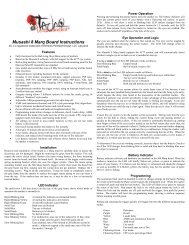
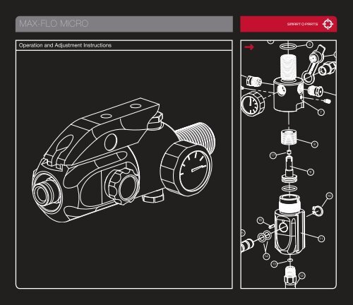
<strong>MAX</strong>-<strong>FLO</strong> <strong>MICRO</strong>1Operation and Adjustment Instructions234520196187817910161511141312
TABLE OF CONTENTS<strong>MAX</strong>-<strong>FLO</strong> <strong>MICRO</strong> WARNINGSGetting FamiliarDepressuring the SystemMax-Flo Exploded ViewDisassemblyReassemblyTroubleshooting01-0203040506-070809Read all warnings, and thisentire manual thoroughly.Failure to heed warningsmay result in property damage,serious injury or death.OBSERVE THESE WARNINGS AND ALL OTHERS THAT APPEAR THROUGHOUTANY MANUAL PROVIDED BY SMART PARTS, INC.:— The Max-Flo Micro is not a toy. Careless or improper use, including failure to followinstructions in the operator’s manual, <strong>co</strong>uld cause death or serious injury.— Read Operators Manual before use and <strong>co</strong>mply with all safety instructions.— Paintball industry standard head/face/throat/eye protection designed for paintballgames must be worn by user and any person within 200 yards (183 meters) whenused in <strong>co</strong>njunction with a paintball marker.— A purchase age of at least 18 (eighteen) years is re<strong>co</strong>mmended for paintballequipment.— Persons under 18 years of age must have adult supervision when using orhandling the Max-Flo Micro.— Observe all local laws, regulations, and guidelines <strong>co</strong>ncerning use.— Use only on professional paintball fields where <strong>co</strong>des of safety are strictlyenforced.— Use <strong>co</strong>mpressed AIR or NITROGEN only. DO NOT USE CO2.— Use to power 0.68 caliber paintball markers only.While every effort has been made to ensure that the information <strong>co</strong>ntained in this guide is accurate and <strong>co</strong>mplete, no liabilitycan be accepted for errors or omissions. Smart Parts, Inc. reserves the right to change the specifications of the Max-Flo Microat any time without prior notice. The latest version of this manual may be downloaded free of charge at www.SmartParts.<strong>co</strong>m.©2007 Smart parts, inc. Smart parts®, Crosshair® logo, Equipment Counts® and Max-Flo Micro aretrademarks or registered trademarks owned by Smart Parts, Inc. Max-flo Micro is <strong>co</strong>vered by patents:5,755,213; 5,957,119. Additional patents pending.800.922.2147 www.smartparts.<strong>co</strong>m00
<strong>MAX</strong>-<strong>FLO</strong> <strong>MICRO</strong> WARNINGS– Never use oil or hydrocarbon <strong>co</strong>mpounds on or in the Max-Flo Micro or its pressure cylinder. The onlysuitable lubricant is Dow 33 grease (SL33K or Shocker lube). The use of inappropriate lubricants may resultin spontaneous ignition, explosion or oxidization.– The belleville washer spring packs and spacer used in the standard and low-output versions of the Max-FloMicro look nearly identical and are not interchangeable. Take extreme care to never separate or mix spring/spacer sets as a mismatch can cause abnormally high output pressures.– Do not expose cylinder or Max-Flo Micro to ambient temperatures above 110 degrees (F) or 43 degrees (C).– Never purge or fill the Max-Flo Micro in <strong>co</strong>nfined spaces or near open flames. Air under pressure will aidin <strong>co</strong>mbustion. Nitrogen in high <strong>co</strong>ncentrations can cause asphyxiation; therefore, adequate ventilationis required.– Vented gases at high pressure can emit high sound levels, which may cause hearing damage. Useappropriate hearing protection for all persons exposed to sound.– Never use damaged hoses or fittings. Split, torn, crushed hoses may fail in a violent manner. Inspect allhoses and fittings at regular intervals.– Never over-tighten any threads or fittings as excessive torque can cause damage which may lead toviolent failure.– Do not transport pressurized gas cylinders.– Never direct pressurized gas toward your skin or any part of your body, as serious injury may result. In thecase of hose, seal or burst disk failure, immediately get away from the venting gas to avoid direct exposure.– Do not use the Max-Flo Micro to blow debris around or for any purpose other than powering a paintballmarker as serious injury to yourself and others may result.– Never pressurize the cylinder/system beyond its safe working pressure.– Never use in<strong>co</strong>rrect safety rupture devices. In the event of rupture of the captive burst disc, the burst discshould only be replaced by a trained, certified technician. The 3000psi Max-Flo Micro has a 5000psi highpressure burst disc; the 4500psi MaxFlo Micro has a 7500psi high pressure burst disc. Use of an in<strong>co</strong>rrect©2005 burst SMART disk PARTS, assembly INC. SMART <strong>co</strong>uld PARTS®, <strong>co</strong>ntribute CROSSHAIR® to LOGO, the cylinder EQUIPMENT exploding, COUNTS® AND which <strong>MAX</strong>-may result in injury or death.<strong>FLO</strong> <strong>MICRO</strong> ARE TRADEMARKS OR REGISTERED TRADEMARKS OWNED BY SMART PARTS, INC.<strong>MAX</strong>-<strong>FLO</strong> <strong>MICRO</strong> IS COVERED BY PATENTS: 5,755,213; 5,957,119. ADDITIONAL PATENTS PENDING.800.922.2147 www.smartparts.<strong>co</strong>m01
<strong>MAX</strong>-<strong>FLO</strong> <strong>MICRO</strong> WARNINGS– Only use the Max-Flo Micro with a gas cylinder that has been tested and certified as <strong>co</strong>mpliant to DOT (USDepartment of Transportation,) HSE, PI (Europe) standards. Do not use the Max-Flo Micro with a gascylinder for which the certification has expired – most DOT exemptions must be renewed by certifiedhydrotesting and inspection every 3 or 5 years.– Only use suitable fill stations that are fitted with industry standard <strong>co</strong>nnectors. Inspect all <strong>co</strong>nnectorsprior to filling for signs of wear, abuse, suitability, dirt or debris. Filling is only to be carried out by<strong>co</strong>mpetent, trained personnel. All persons in the immediate fill area must wear suitable eye protection andremain clear of vented gasses. Do not fill the Max-Flo Micro system beyond the operational pressure ratingof the cylinder to which it is attached. Never fill the Max-Flo Micro system to pressure above 4,500 psi.– Fast filling of cylinders results in heating of the gas and cylinder. If filled too fast, this heat can be<strong>co</strong>meexcessive which may cause damage to the cylinder. Such damage can lead to failure of the cylinder,causing potential property damage and personal injury. Care must be taken so that the cylindertemperature does not exceed 130 degrees F (55 degrees C).– Prior to each filling, the cylinder must be examined for signs of damage, including heat/flame exposure.If any damage is observed, do not fill the cylinder. Take the suspect cylinder to a DOT or HSE authorizedhydrostatic tester for inspection and pressure testing.– The cylinder can fly off with enough force to injure or kill if the cylinder is unscrewed while pressurized.Improper use, filing, storage or disposal may result in property damage, serious injury, or death. Thecylinder must only be filled by properly trained personnel. Do not expose to temperatures exceeding 130degrees F (55degrees C), when pressurized. Do not modify the cylinder in any way, or place any stickers onthe cylinder.– In ac<strong>co</strong>rdance with the United States Transportation Security Agency, the Max Flo Micro regulator must beremoved from the cylinder prior to transport in checked luggage on <strong>co</strong>mmercial passenger aircraft.– This precaution list and operator’s manual must always ac<strong>co</strong>mpany the product in the event of resale ornew ownership. The latest version of this manual is available for free download at www.SmartParts.<strong>co</strong>m.– SHOULD YOU BE UNSURE AT ANY STAGE, YOU MUST SEEK EXPERT ADVICE.©2005 SMART PARTS, INC. SMART PARTS®, CROSSHAIR® LOGO, EQUIPMENT COUNTS® AND <strong>MAX</strong>-<strong>FLO</strong> <strong>MICRO</strong> ARE TRADEMARKS OR REGISTERED TRADEMARKS OWNED BY SMART PARTS, INC.<strong>MAX</strong>-<strong>FLO</strong> <strong>MICRO</strong> IS COVERED BY PATENTS: 5,755,213; 5,957,119. ADDITIONAL PATENTS PENDING.800.922.2147 www.smartparts.<strong>co</strong>m02
GETTING FAMILIARIMPORTANTThe Max-Flo Micro preset <strong>co</strong>mpressed air system provides the stabilityand high flow rates that have made the Max-Flo line of regulators thechoice of champions, <strong>co</strong>mbined with an easy to use pre-set <strong>co</strong>nfiguration.A <strong>co</strong>mbination of increased air-flow rates, decreased weight and lowermaintenance makes the Max-Flo Micro an ideal choice.– Complies with airline travel regulations– User-friendly, rebuildable, inline on/off– Preset to 800 psi (standard) or 450 psi (low-output model) output pressure.– Includes Smart Parts S-rail (<strong>co</strong>mpatible with industry standard 1/2” air system rails)FIG. 1<strong>MAX</strong>-<strong>FLO</strong> <strong>MICRO</strong>This manual is for a 3000psi or 4500psi system. Please refer to the sticker on theunderside of the regulator. A 3000psi regulator should only be used with a 3000psirated tank, and a 4500psi regulator should only be used with a 4500psi rated tank.Always release all pressure from your air tank by dis<strong>co</strong>nnecting the macroline hosebetween the regulator and the gun, and turning the on/off valve to on to release thepressure before removing the cylinder.Always wear <strong>co</strong>rrect eye protection when working on any high pressure system.The cylinder can fly off with enough force to kill if the cylinder is unscrewedwhile pressurized. Improper use, filing, storage or disposal may result in propertydamage, serious injury, or death. The cylinder must only be filled by properly trainedpersonnel. Do not expose to temperatures exceeding 130 degrees F (55 degrees C),when pressurized. Do not modify the cylinder in any way, or place any stickers onthe cylinder.©2005 SMART PARTS, INC. SMART PARTS®, CROSSHAIR® LOGO, EQUIPMENT COUNTS® AND <strong>MAX</strong>-<strong>FLO</strong> <strong>MICRO</strong> ARE TRADEMARKS OR REGISTERED TRADEMARKS OWNED BY SMART PARTS, INC.<strong>MAX</strong>-<strong>FLO</strong> <strong>MICRO</strong> IS COVERED BY PATENTS: 5,755,213; 5,957,119. ADDITIONAL PATENTS PENDING.800.922.2147 www.smartparts.<strong>co</strong>m03
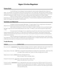
DEPRESSURING THE SYSTEM01 02While wearing paintballeye and face protectionin a safe, well ventilatedarea, turn the on/off valveto the OFF position andunload the paintballmarker to which the Max-Flo Micro is attached.04Secure a barrel blockingdevice on the marker anddry-fire the marker untilany remaining pressureis relieved. If the markeris equipped with an antichopsystem it must beturned off to dry-fire.0305 06Remove the macrolinehose fromthe macro-linefitting on the frontof the regulator.Direct the macroline Once gas can no longer be The cylinder shouldfitting on the front of the heard escaping from the only be removed ifregulator away from any Max-Flo Micro, the system you are changingpersons, animals, loose should be depressurized. tanks or transportingby airplane.debris or anything fragile, Verify that no pressure registerson the Max-Flo Microand slowly turn the on/offvalve to the ON positionpressure gauge.to release any pressure©2005 from SMART the cylinder. PARTS, INC. SMART PARTS®, CROSSHAIR® LOGO, EQUIPMENT COUNTS® AND <strong>MAX</strong>-<strong>FLO</strong> <strong>MICRO</strong> ARE TRADEMARKS OR REGISTERED TRADEMARKS OWNED BY SMART PARTS, INC.<strong>MAX</strong>-<strong>FLO</strong> <strong>MICRO</strong> IS COVERED BY PATENTS: 5,755,213; 5,957,119. ADDITIONAL PATENTS PENDING.Once depressurized,the gauge onthe Max-Flo Microshould read Zero (0)psi, and no sound ofescaping gas shouldbe heard when theon/off valve is turnedto the on position(with no macroline<strong>co</strong>nnected.) If youcan not <strong>co</strong>mpletelydepressurize yourMax-Flo Microsystem, <strong>co</strong>ntactSmart Parts technicalsupport forassistance. NEVERremove the cylinderor disasemble theMax-Flo Micro withany pressure remainingin the system.800.922.2147 www.smartparts.<strong>co</strong>m04
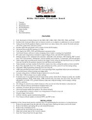
<strong>MAX</strong>-<strong>FLO</strong> <strong>MICRO</strong> PARTSEXPLODED DIAGRAMFIG. 2MAJOR <strong>MAX</strong>-<strong>FLO</strong> <strong>MICRO</strong> COMPONENTSStandard Output800 psi Spring PackLow-Output450 psi Spring Pack1 CLP003 – FILTER, RETAINING CLIP2 IMF110 – FILTER3 ORN90790NT – NECK O-RING4 <strong>MAX</strong>COVBLK – FILL NIPPLE COVER5 FIT18MNPTXMQDCNPL – FILL NIPPLE ASSEMBLY,6 HIGH PRESSURE RUPTURE DISK (See Page 09)7 MFP102 – <strong>MAX</strong>-<strong>FLO</strong> <strong>MICRO</strong> REAR BODY8 SPRING PACK9 MFP105 – <strong>MAX</strong>-<strong>FLO</strong> <strong>MICRO</strong> PISTON10 CLP002 – ON/OFF RETAINING CLIP11 MFP101BLK – <strong>MAX</strong>-<strong>FLO</strong> <strong>MICRO</strong> FRONT BODY12 FIT18MNPTX14PTC – STRAIGHT MACROLINE FITTING13 ORN00490UR – OUTPUT O-RING14 ORN01070UR – ON/OFF O-RING (2x)15 VLVSMT102BLK – BLACK ON/OFF VALVE16 PIN001 – ON/OFF STOP PIN17 0RN01470UR – PISTON O-RING18 MFP103 – PISTON SEAL19 GAG6000SHT – 0-6000 PSI <strong>MICRO</strong> GAUGE20 SCRN0632X0250SDO – BODY LOCKING SCREW (2x)21 RUP1800 – LOW PRESSURE BURST DISK (1,800 psi)22 SPR026 – 800 PSI BELLEVILLE WASHER (x10)23 MFP107 – 450 PSI SPRING SPACER24 SPR026LO – 450 PSI BELLEVILLE WASHER (x12)25 ORN0107OUR – O-RING800.922.2147 www.smartparts.<strong>co</strong>m05
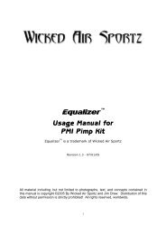
DISASSEMBLYIf working with the Max-Flo Micro while it is attached to a marker, <strong>co</strong>mplywith marker manual warnings.The Max-Flo Micro is a preset, closed system; it is very difficult for dirt anddebris to enter and damage the system. Consistent use of the suppliedfill nipple <strong>co</strong>ver is your best protection against system <strong>co</strong>ntaminationand damage. Should dirt enter your air cylinder, an internal filter protectsthe internals of the Max-Flo Micro from damage. The amount of regularmaintenance and cleaning of your Max-Flo Micro system requires willdepend on the amount of use and the cleanliness of your air source fillings.As with any other disassembly, disassemble this regulator on a cloth, on atable, and not at the field.Please follow the guidelinesfor depressurizing yoursystem before removing thecylinder from the Max-FloMicro regulator. Your gaugeshould read zero (0) andyour marker should notpressurize when the on/offvalve is turned on. If yourmarker does pressurize,please repeat the steps fordepressurizing your system.REQUIRED ALLEN WRENCHES01 02031//16” 3/32”ADDITIONALREQUIRED ITEMS· Smart Parts SL33K or Shocker Lubricant· Lint-free cloth or paper towels· Blue (#242) Loctite® or equivalentRemove the Maxflosystem fromthe mounting rail,using a 3/32” allenwrench. Unscrewthe cylinder from theMax-flo regulator.Remove the two bodylocking screws using a1/16” allen wrench. Thesescrews are secured at thefactory with temporarythread locking <strong>co</strong>mpound.Slow and steady pressurewill remove them.Unscrew theMax-Flo Microbody front fromthe rear Max-FloMicro body.800.922.2147 www.smartparts.<strong>co</strong>m06
DISASSEMBLYPLEASE READ CAREFULLY04The Max-Flo Micro is available in standard (800 psioutput) and low-output (450 psi) models. Low-outputmodels are identified by laser engraving in their dovetailrail slot. The standard model utilizes a spring packmade of 10 belleville washers (a slightly <strong>co</strong>ne shapedwasher.) The low-output model has a spring pack<strong>co</strong>nsisting of 12 belleville washers and a spacer. Springpacks should only be changed or installed as <strong>co</strong>mpletesets, as they use different strength washers which lookidentical to the naked eye.060705With the body separated, locate the Max-Flo Micropiston and spring pack. If the spring pack isexposed, remove it first. Be careful as the springpack may fall into separate pieces. The bellevillewashers (and spacer in the 450 psi low-outputmodel) may be wiped off if necessary. If thespring pack is not exposed, carefully remove thepiston and then the spring pack. The Max-FloMicro piston may be removed by gently pulling itaway from the front regulator body.Remove any Belleville washerswhich may remain in the rearregulator body. To do this, turnthe Max-Flo Micro rear regulatorbody upside down and gently tapit on a hard surface.Clean the Max-Flo Micro piston with a lint free cloth. Inspect both theregulator piston seal and o-ring for signs of wear or damage. If necessaryreplace worn or damaged seals. Clean and inspect all parts. Shouldthe macroline fitting need to be removed, insert a 5/32” allen wrench intothe fitting, or use a 7/16” deep well socket. Inspect all o-rings and sealsfor cuts, flat spots or other damage and replace as necessary.Any further disassembly should be performed by a Smart Parts technician.©2005 SMART PARTS, INC. SMART PARTS®, CROSSHAIR® LOGO, EQUIPMENT COUNTS® AND <strong>MAX</strong>-<strong>FLO</strong> <strong>MICRO</strong> ARE TRADEMARKS OR REGISTERED TRADEMARKS OWNED BY SMART PARTS, INC.<strong>MAX</strong>-<strong>FLO</strong> <strong>MICRO</strong> IS COVERED BY PATENTS: 5,755,213; 5,957,119. ADDITIONAL PATENTS PENDING.800.922.2147 www.smartparts.<strong>co</strong>m07
REASSEMBLYPLEASE READ CAREFULLY01Using SL33K or Shocker Lubricant, grease the piston o-ring and apply a smallamount of lubricant to the shaft of the piston. Following the diagram for the<strong>co</strong>rrect Max-Flo Micro model (standard or 450 psi output) stack the bellevillewashers (and spacer for 450 psi model) onto the piston shaft prior to installingthe assembly.Make sure to align the washers as shown in the exploded parts diagram.In<strong>co</strong>rrect stacking or use of wrong washer type will result in unpredictablepressure level output.03Screw the two halves of the regulator body together. You may usea small amount of blue Loctite® #242 on the threads of the frontregulator body. DO NOT use thread sealant tape. Use the S-Railto aid assembly of the two regulator halves. This will help line upthe two halves <strong>co</strong>rrectly. Replace the two set screws in front ofthe two burst (rupture) discs, using blue Loctite® #242.Do not over tighten screws. Hand torque is sufficient. The screwsmust sit flush with the regulator body. The screws will sit flushwhen the regulator body is alligned. If the screws do not sit flush,then the body halves are not aligned.0402Once the spring pack isassembled on the piston,slide the entire assemblyinto the shaft in the frontof the regulator body. Removeany excess greasefrom the white regulatorpiston seal.Slide the Max-Flo Micro onto yourmounting rail. Screw the cylinder backonto the Max-Flo Micro regulator. Ensurethe cylinder screws freely onto theregulator body.Ensure that no space exists between thecylinder and Max-Flo Micro regulatorbody. The cylinder must fit tightly on theregulator. Please return your regulatorto Smart Parts for repair if any noticablewear exists on the threads.800.922.2147 www.smartparts.<strong>co</strong>m08
TROUBLESHOOTINGAIR LEAKS FROM THE FILL NIPPLE.— Debris is in the fill nipple. De-gas system, clean out fill nipple.Use fill nipple <strong>co</strong>ver to prevent from recurring.— Fill nipple assembly is damaged – replace.REGULATOR IS UNDER/OVER PRESSURIZING.— System reassembled with Belleville Spring pack in wrong <strong>co</strong>nfiguration.Reassemble properly (refer to diagram).— Debris has clogged the filter. Clean or replace it.REGULATOR IS SPIKING OR CREEPING IN PRESSURE.— Clean or replace regulator piston o-ring.— Clean or replace piston.ON/OFF VALVE IS LEAKING AND WILL NOT SHUT OFF.— Replace On/Off o-ring.BURST DISK RUPTURES.— Rupture of the high-pressure burst disk indicates that the Max-FloMicro system was filled beyond its pressure rating. Do not overfill!Have the burst disk replaced by a trained, certified technician– 5,000 psi burst disk (#RUP5000) for 3,000 psi systems, 7,500 psiburst disk (#RUP7500) for 4,500 psi systems.— If the 1800 psi burst disk ruptures, have it replaced and replace theregulator piston assembly (available in the MFP201 rebuild kit.)©2005 SMART PARTS, INC. SMART PARTS®, CROSSHAIR® LOGO, EQUIPMENT COUNTS® AND <strong>MAX</strong>-— If the 1800 psi burst disk ruptures again shortly after repair, the<strong>FLO</strong> <strong>MICRO</strong> ARE TRADEMARKS OR REGISTERED TRADEMARKS OWNED BY SMART PARTS, INC.<strong>MAX</strong>-<strong>FLO</strong> system <strong>MICRO</strong> IS should COVERED be BY returned PATENTS: 5,755,213; to Smart 5,957,119. Parts, ADDITIONAL Inc. for service. PATENTS PENDING.DO NOT ATTEMPT TO REPLACEBURST DISCS YOURSELF.Never use in<strong>co</strong>rrect safety rupturedevices. The 3000psi Max-FloMicro has a 5000psi burst disc;the 4500psi Max-Flo Micro has a7500psi burst disc. The one-pieceburst disc/nut assembly used onthe Max-Flo Micro in<strong>co</strong>rporatesa captive burst disc in its burstnut. The one-piece burst disc/nutassembly supplied is only for usewith the Max-Flo Micro and noother applications. In the eventof rupture of the captive burstdisc, the burst disc should onlybe replaced by a trained, certifiedtechnician. The one piece burstdisc/nut assembly should only bereplaced with another one-piecebust disc/nut assembly, and notwith a separate <strong>co</strong>pper burst disc.The fitting of a separate burstdisc with the one-piece burstdisc/nut assembly can result inthe pressure relief safety deviceon the regulator failing to operate<strong>co</strong>rrectly. This <strong>co</strong>uld lead to thecylinder exploding which mayresult in serious injury or death.800.922.2147 www.smartparts.<strong>co</strong>m09
800.922.2147 100 Station St. Loyalhanna, PA 15661 www.smartparts.<strong>co</strong>m manual version 2.1