Semi-Automatic Switchover System Operation Manual - Genstar ...
Semi-Automatic Switchover System Operation Manual - Genstar ...
Semi-Automatic Switchover System Operation Manual - Genstar ...
- No tags were found...

Create successful ePaper yourself
Turn your PDF publications into a flip-book with our unique Google optimized e-Paper software.
<strong>Semi</strong>-<strong>Automatic</strong> <strong>Switchover</strong> <strong>System</strong><strong>Operation</strong> <strong>Manual</strong><strong>Genstar</strong> Technologies Co. Inc.4525 Edison Ave.Chino, CA 91710Tel: 909-606-2726Fax: 909-606-64851
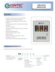
IntroductionThe GENTEC P3400 and PD3400 Series <strong>Semi</strong>-<strong>Automatic</strong> <strong>Switchover</strong> <strong>System</strong> are used for adjusting or controlling, smallflow, compressed gas manifold systems without interrupting the system during switchover. The switchover occursautomatically, once the primary bank (in use) gas supply runs low, the reserve bank then becomes the primary bank. Thearrow on the handle bar on the right end bank regulator indicates the designated primary bank, which the operator maychange. The outlet pressure may be calibrated to meet customer needs. See Figure 1 and Figure 2 for a diagram of theswitchover system.Features:Dual Bank gas supply and semi-automatic changeoverDual Stage Pressure Reduction minimizes pressure and flow fluctuationAll components mounted on a single panel for easy maintenanceInlet Valve(s) for changing cylinders included. Outlet and Vent Valves optional.High Flow <strong>System</strong> optionalDiaphragm valve connections are orbital welded to minimize contamination and leakage.Note: Stainless Steel Models only.Specifications:Maximum Inlet Pressure: 4500 psigMaximum Outlet Pressure: 50/100/150/250 psigOperating Temperature Range: -40 ○ F to 165 ○ FLeak Rate: 2x10 - 8 atm.cc/sec HeCv: 0.08Materials of Construction:<strong>System</strong> Panel: Aluminum AlloyRegulator Body: Ni Plated Brass or 316 Stainless SteelRegulator Seat: PCTFE for Bank Regulators, PTFE for Line RegulatorInlet Pressure Gauge: Brass or 316 Stainless SteelDelivery Pressure Gauge: Brass or 316 Stainless SteelDiaphragm Valves: 316 Stainless SteelRelief Valve: Brass or 316 Stainless SteelPigtails: Flexible std. or Rigid 316SSPanel Inlet/Outlet Connections: ¼” Genlok std.Manifold Options:Manifold Piping to 10 cylinders6ft Flex HosesCylinder HoldersElectric Contact GaugesAlarm Box2
P3400Figure 1 (<strong>Switchover</strong> Manifold w/o pressure adjusting regulator)PD3400Figure 2 (w/Adjustable Regulator and Tee Purge Option)3
Principle of <strong>Operation</strong>The Left Bank Regulator outlet pressure is preset and non-adjustable, at a pressure of P i . The Right Bank pressure isadjusted only within a certain range by the 180 degrees movement of the handle bar. When the arrow is pointing left, theoutlet pressure of the Right Bank Regulator 2 is P 1 , and when the arrow is pointing right, the outlet pressure is P 2 , wherepressure P 2 > P 1 . The Left Bank Regulator pressure P i is equal to (P 1 + P 2 )/2.。While the arrow is pointing left, P 1 is < P i ,therefore the gas is supplied through the left bank. While the arrow is pointing right, P 2 > P i , therefore the gas is suppliedthrough the right bank.The Line Regulator outlet pressure can be adjusted by turning the regulator knob. The Left Bank and Right Bank PressureGauges display the respective inlet pressure. The Line Pressure Gauge displays the system outlet pressure.1. Primary bank and reserve bank setup:While both bank cylinders are full, the operator can designate either side to become the primary bank. For example,when the arrow is pointing to the left, the left bank is designated as the primary bank and the right bank as the reservebank. If the operator chooses to turn the arrow to the right first, then the right bank would be designated as the primarybank and left bank becomes the reserve bank.2. Replacing cylinders and operation:When the primary bank gas supply is almost depleted, the switchover will occur automatically, meaning the reservebank is now in use. The operator may verify which bank is depleted by reading the inlet pressure gauge. When theswitchover occurs, the operator must replace the cylinders on the depleted bank immediately. Note: Before replacingthe cylinders, remember to turn the arrow 180 degrees to designate the other bank as the primary bank.3. Adjusting the system outlet pressure:The outlet pressure is displayed by the pressure gauge on the line regulator. The outlet pressure of line regulator isadjusted by turning the pressure knob in line clockwise for higher pressure and vice versa.4. Tee Purge Option for Inert Gases, (excludes flammable gases):Vent Valves are used during cylinder changeover on both right and left side of the manifolds to remove residualimpurities that may be trapped in line. Vent Valves are set up as tee purge with both inlet and vent valves on both sidesof the manifold. When the right side switchover occurs, the user should turn and point the arrow knob in the direction ofusage. The user should remove the depleted cylinder by disconnecting the cylinder hose assembly, and then reconnectthe hose assembly to the new cylinder. Ensure that the hose assembly is tightened accordingly before opening thecylinder valve. When the cylinder is replaced and ready for operation, ensure both the inlet and vent valves are closed.Open the cylinder valve, then inlet valve, then vent valve as part of the tee purge for purging out any residual impurities.Close the vent valve and the inlet valve, and then repeat the cycle as needed. 5-10 purge cycles should be suitable forinert gases.4
AssemblyMeasure the position at which the switchover system is to be assembled, ensure that it is at a location convenient forboth the operator and maintenance personnel. The switchover system shall be placed in a well-ventilated facility, andmust be away from flammable materials and open fire. There are four assembly holes on the mount, which areintended to be used with expansion screws or bolts to mount the switchover system against the wall or assembly rack.P3400PD34005
MaintenanceDaily maintenance should be done by trained personnel only:1. Record the outlet/piping pressure.2. Verify that the regulator, header bar, pigtail connections do not have leakage.3. Check the regulator for creep; must maintain regulator immediately if creep is present.6