View Machinery Manual for 105-1300 - Enco
View Machinery Manual for 105-1300 - Enco
View Machinery Manual for 105-1300 - Enco
- No tags were found...

You also want an ePaper? Increase the reach of your titles
YUMPU automatically turns print PDFs into web optimized ePapers that Google loves.
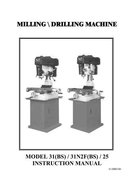
MILLING \ DRILLING MACHINEMODEL 31(BS) / 31N2F(BS) / 25INSTRUCTION MANUAL31-100827-R4
! WARNING !Some dust created by power sanding, sawing,grinding, drilling, and other construction activitiescontains chemicals known to the State of Cali<strong>for</strong>nia tocause cancer, birth defects or other reprodrctive harm.Some examples of these chemical are:‧Lead from lead-based paints.‧Crystalline silica from bricks, cement and othermasonry products.‧Arsenic and chromium from chemically-treatedlumber.Your risk from these exposures varies, depending onhow often you do this type of work. To reduce yourexposure to these chemicals: Work in a well ventilatedarea, and word with approved safety equipment, suchas those dust masks that are specially designed tofilter out microscopic particles.
Table Of ContentsPage No1 Overall Aspect ………………………………………………………………… 22 Safety Rules For tools ………………………………………………………… 33 Specification …………………………………………………………………… 54 Features ……………………………………………………………………..… 65 Delivery & Installation …………………………………………………….. 66 Minimum Room Space For Machine Operation …………………………… 87 Use Of Main Machine Parts ……………………………………………….… 88 Precaution For Operation …………………………………………………… 99 Adjusting Table Slack And Compensate For Wear ………………………. 1010 Clamping /Table Base And Machine Base …………………………………. 1111 Speed Changing And Adjust Belt …………………………………………… 1112 To Change Tools ……………………………………………………………… 1213 Ordering Replacement Parts ………………………………………………… 1214 Extra Tooling And Accessories ……………………………………………. .. 1215 Tapping Equipment ………………………………………………………….. 1316 Spindle Power Down Feed Operation …..…………………………………... 1317 Specification Of T Slot ……………………………………………………….. 1418 Maintaining ……………………………………………………………….….. 1419 Cleaning & Lubricating …………….……………………………………… 1420 Trouble Shooting ……………………………………………………………... 1521 Circuit Diagram ……………………….……………………………………… 1822 Parts Lists …………………………………………………………………… 21- 1-
Overall Aspect- 2-
WARNING: FAILURE TO FOLLOW THESE RULESMAY RESULT IN SERIOUS PERSONAL INJURYAs with all machinery there are certain hazards involved with operation and use of the machine.Using the machine with respect and caution will considerably lessen the possibility of personalinjury. However, if normal safety precautions are overlooked or ignored, personal injury to theoperator may result.This machine was designed <strong>for</strong> certain applications only. We strongly recommends that thismachine NOT be modified and/or used <strong>for</strong> any application other than <strong>for</strong> which it was designed. Ifyou have any questions relative to its application DO NOT use the machine until you contact withus and we have advised you.Your machine might not come with a power socket or plug. Be<strong>for</strong>e using this machine, pleaseDo ask your local dealer to install the socket or plug on the power cable end.SAFETY RULES FOR ALL TOOLSA. USER:1. WEAR PROPER APPAREL. No loose clothing, gloves, rings, bracelets, or other jewelry toget caught in moving parts.Non-slip foot wear is recommended. Wear protective hair covering to contain long hair.2. ALWAYS WEAR EYE PROTECTION. Refer to ANSLZ87.1 standard <strong>for</strong> appropriaterecommendations.Also use face or dust mask if cutting operation is dusty.3. DON'T OVERREACH. Keep proper footing and balance at all times.4. NEVER STAND ON TOOL. Serious injury could occur if the tool is tipped or if the cuttingtool is accidentally contacted.5.NEVER LEAVE TOOL RUNNING UNATTENDED. TURN POWER OFF. Don't leavetool until it comes to a complete stop.6. DRUGS, ALCOHOL, MEDICATION. Do not operate tool while under the influence of drug,alcohol or any medication.B. USE OF MACHINE:1. DON'T FORCE TOOL. It will do the job better and be safer at the rate <strong>for</strong> which it wasdesigned.2. USE RIGHT TOOL. Don't <strong>for</strong>ce tool or attachment to do a job <strong>for</strong> which it was not designed.3. SECURE WORK. Use clamps or a vise to hold work when practical. It's safer than using your- 3-
hand frees both hands to operate tool.4. USE RECOMMENDED ACCESSORIES. Consult the owner's manual <strong>for</strong> recommendedaccessories. The use of improper accessories may cause hazards.5. AVOID ACCIDENTAL STARTING. Make sure switch is in “OFF” position be<strong>for</strong>eplugging in power cord.C. ADJUSTMENT :MAKE all adjustments with the power off. In order to obtain the machine. precision and correctways of adjustment while assembling, the user should read the detailed instruction in this manual.D. WORKING ENVIRONMENT:1. KEEP WORK AREA CLEAN. Cluttered areas and benches invite accidents.2. DON'T USE IN DANGEROUS ENVIRONMENT. Don't use power tools in damp or wetlocations, or expose them to rain. Keep work area well-lighted.3. KEEP CHILEREN AND VISITIORS AWAY. All children and visitors should be kept a safedistance from work area.4. DON’T install & use this machine in explosive, dangerous environment.E. MAINTENANCE1. DISCONNECT machine from power source when making repairs.2. CHECK DAMAGED PARTS. To read every details of trouble shooting, repair it verycarefully and make sure the operator won't get injure and damage the machine.Thank you <strong>for</strong> purchasing the 31 MILLING/GRILLING Machine. If properly cared <strong>for</strong> andoperated, this machine can provide you with years of accurate service. Please read this manualcarefully be<strong>for</strong>e using your machine.- 4-
1.SPECIFICATIONMODEL 31(BS) / 31N2F(BS) 25Drilling capacity 32mm(1 1 / 4 ") 25 mm (1")Face mill capacity 76mm(3") 64 mm (2-1/2")End mill capacity 20mm(3/4") 13mm (1/2")Spindle nose to column surface 170mm(6-3/4") 170mm(6-3/4")Max. distance spindle nose to table 430mm(16-7/8") 325 mm(12-3/4")Spindle taper M.T.3 R-8 M.T.3 R-8Spindle stroke 130mm(5-1/8")(N2F=107mm) 90 mm (3-1/2")Diameter of Spindle sleeve 75mm(3") 62 mm (2-7/16")Head swivel 360∘ 360∘Diameter of column 115mm(4-1/2") 92 mm (3-5/8")Overall height (w/o stand) 1240mm(48-7/8") <strong>105</strong>0 mm (41-3/8")Length 990mm(39") 910mm(35-7/8")Width 1100mm(43-3/8") 960mm(37-7/8")Machine stand height 715mm(28-1/8") 715mm(28-1/8")Motor 1-1/2HP - 2HP 3/4HP – 1HPSpindle speed( r.p.m.)Standard accessoriesForward and backward travel oftable50Hz 125-2500 90-215012S 60Hz 150-3000 110-25803"-cutter 1/2" chuck 3 " anglevise- 5 -2 1 / 2 " –cutter 1/2" chuck3" angle vise185mm(7-1/4") 150 mm (5-7/8")Right and left travel of table 430mm(16-7/8") 340 mm (13-3/8")Working area of table 730mm x 210mm(28 3 / 4 "x 8 1 / 4 ") 585mm x 190mm(23"x 7 1 / 2 ")Gross weight 300kgs (660 lbs) 200kgs (440 lbs)Measurement 20’Container Q’ty: 42 sets 20’Container Q’ty: 48 setsExtra accessoriesPower down (spindle) feedTapping switchForward & Reverse switchCollet chuckWork lightForward & Reverse switchCollet chuckWork lightCabinet standClamping kitsCabinet standExtensioncolumn Clamping kitsNoise 80 dB MAX 80 dB MAX
Tools selection & proper material rangeTool type Tool materialWork piece materialEnd mill HSSNon-iron material steel ironTUNGSTEN CARBIDE Cast iron non-iron materialFace mill TUNGSTEN CARBIDE Non-iron material steel ironLight materialDrilling HSS Non-iron material steel ironLight materialTapping HSSNon-iron material steel ironLight material2. FEATURES(1) This machine has, several uses, such as surface cutting, drilling, milling, and also can beequipped with an electric switch <strong>for</strong> tapping.(2) This machine is of fine quality, can be operated easily, and it is not limited to skilled operators.(3) The drilling and milling operation can be per<strong>for</strong>med by two methods:1). Hand operation, which makes quick drilling.2). Worm gear feed operation, which makes slow milling.(4) Bronze adjustable nuts, which adjust the thread clearance and reduce the wear. They also makescrews rotated smoothly and increase the thread accuracy.(5) Whole column which makes this machine strong, stable, and also keep the high accuracy.(6) Head of tough cast ensures its accuracy lasting and enduring through the treatment of preciseboring cylinder, grinding, and internal stress relief.(7) To adjust belt and change speed, new pulley cover is easy to open the cover.3. DELIVERY & INSTALLATIONUnpacking1. Transportation to desired location be<strong>for</strong>e unpacking, please use lifting jack.(Fig. B)2. Transportation after unpacking, please use heavy duty fiber belt to lift up the machine.ALLWAYS KEEP PROPER FOOTING & BALANCE WHILE MOVING THIS MACHINE.- 6 -
Fig. BInstallation:(1) BE SURE all locks of head-stock & column are tighten be<strong>for</strong>e operation.(2) ALWAYS Keep proper footing & balance while moving this 300kgs machine. And only useheavy duty fiber belt to lift the machine as per Fig. A.(3) KEEP machine always out from sun, dust, wet, raining area.(4) POSITION & tighten 4 bolts into base holes properly aftermachine in balance.(5) TURN OFF the power be<strong>for</strong>e wiring & be sure machine inproper grounding. Overload & circuit breaker is recommended<strong>for</strong>safety wiring.(6) CHECK carefully if main shaft in clockwise direction whilerunning test. If not, reverse the wiring then, repeat the test tillspindle direction is correct.(7) Finish removing this wooden case/crate from the machine.Unbolt the machine from the crate bottom.(8) Carefully lift the machine to a sturdy stand or work bench. For best per<strong>for</strong>mance, through boltthe machine to bench or stand.(9) Bolt the stand legs to the floor, while using a sturdy stand.Be<strong>for</strong>e Bolting The Machine To A Bench Or Stand Or Floor, The Unit Must Be Level In BothDirections.- 7 -
4. MINIMUM ROOM SPACE FOR MACHINE OPERATIONFor 31/31N2F For 255. USE OF MAIN MACHINE PARTS (See Fig. l)(1) To raise and lower the head by head handle.(2) Equipped with an electric switch <strong>for</strong> tapping operation clockwise or counterclockwise.(3) To adjust the quick or slow feeding by feed handle.(4) To adjust the table left and right travel by table handle wheel.(5) To adjust the table <strong>for</strong>e and aft travel by table handle wheel.(6) To operate the spindle handle wheel <strong>for</strong> micro feed.(7) To adjust the scale size according to working need.(8) Switch button function description.(a) Be<strong>for</strong>e starting the machine turn the selectionknob (A) to (right <strong>for</strong> clock wise running, left<strong>for</strong> counter clock vise)(b) Push button (C) to start the machine.(c) Push button (B) to stop the machine.(d) When in emergency push button to stop themachine. after clearing the trouble, releaseemergency button, re-start the machine bypushing the start button.- 8 -
QUILL RETURN SPRING ADJUSTMENT:Spring tension <strong>for</strong> return of spindle, after hole drilling, has been pre-set at the factory. No furtheradjustment should be attempted unless absolutely necessary. Adjustment will probably berequired if a multiple drilling or tapping head is used. If adjustment is necessary, loosen lock screwwhile holding. Do not allow the housing to turn in your hand, or spring will unwind. Turn entirehousing assembly clockwise the number of turns necessary to cause the quill to return to its upposition. (NOTE. The flat of the spring housing pilot is lined up with the spring loading hole on thebody of the spring housing.) Reset lockscrew make sure point of screw mates to flat on the housingjournal.7. ADJUSTING TABLE SLACK AND COMPENSATE FOR WEAR (see Fig. 3)(1) Your machine is equipped with Jib strip adjustment to compensate <strong>for</strong> wear and excess slackon cross and longitudinal travel.(2) Clockwise rotation the job strip bolt with a big screw <strong>for</strong> excess slack otherwise a little counterclockwise if too tight.(3) Adjust the jib strip bolt until feel a slight drag when shifting the table.- 10-
8. CLAMPING, TABLE BASE, AND MACHINE BASE (see Fig. 3)(1) When milling longitudinal feed, it is advisable to lock the cross feed table travel to insure theaccuracy of your work. To do this, tighten the small leaf screw located on the right side of thetable base.(2) To tighten the longitudinal feed travel of the table <strong>for</strong> cross feed milling, tighten the two smallleaf screw on the front of the table base(3) Adjustable travel stops are provided on the front of the table <strong>for</strong> control of cross travel and thedesired milling length.9. SPEED CHANGING AND ADJUST BELT (Step See Fig. 4)(1) Turn power off.(2) Open belt cover by releasing side latches step see(a)(b)(c).(3) Loosen motor mount leaf screw.(4) Push motor in order to loosen belts(head side of motor mount is set fixed, two motor's ear sidewith motor screw to tighten or loosen of belts.)(5) Loosen two screws <strong>for</strong> base of speed change inter pulley that also adjust the location of base <strong>for</strong>speed change inter pulley.(6) Select the suitable R.P.M. from speed charts of table 1. Then place the belts on the desiredpulley steps.(7) Tighten two screws of base <strong>for</strong> speed change pulley and the bolt of motor mount lock.(8) Cover the belt cover be<strong>for</strong>e turnning power on.- 11-
12 SPEEDS BELT 12 SPEEDS BELT50Hz 60Hz 50Hz 60Hz125 150 4-5 710 850 1-6185 225 3-5 1000 1200 2-7210 255 4-6 1250 1500 3-8300 350 2-5 1350 1600 1-7350 400 3-6 1900 2300 2-8420 500 4-7 2500 3000 1-8Table .1 For 31/31N2FFor 2510. TO CHANGE TOOLS(1) Removing Face Mill or Drill Chuck ArborLoosen the arbor bolt (see fig. 4) at the top of the spindle shaft approximately 2 turns with awrench. Rap the top of the arbor bolt with a mallet. After taper has been broken loose, holdingchuck arbor on hand and turn detach the arbor bolt with the other hand.(2) To Install Face Mill or Cutter ArborInsert cutter and cutter arbor into the taper of spindle. Tighten arbor bolt detach securely, but donot over-tighten.(3) Removing Taper Drills(a) Turn down the arbor bolt and insert the taper drill into the spindle shaft.(b) Turn the rapid down handle rod down until the oblong hole in the rack sleeve appears.Line up this hole with the hole in the spindle. Insert key punch key through holes and strikelightly with a mallet. This will <strong>for</strong>ce the taper drill out.11. ORDERING REPLACEMENT PARTSComplete parts list is attached. If parts are needed, contact your local distributor.12. EXTRA TOOLING AND ACCESSORIESEach of machines is equipped with a MT # 3 spindle taper or a R-8 spindle taper (examples below).Contact your local distributor or a major cutting tool distributor to obtain any of these accessories.Taper DrillsReamers- 12-
End MillsCutter ArborTapsColletsAdapters and Sleeves13. TAPPING EQUIPMENTThis machine can be equipped with an electric switch <strong>for</strong> tapping operation clockwise orcounter-clockwise, and the working depth also can be adjusted by the limit switch. (Electric switchwill be installed according to your requirement, and you must pay the cost only.)14. SPINDLE POWER DOWN FEED OPERATION1. Select profitable spindle speed and automatic feeding rate according to cutting condition.By adjusting the shift dial A you can obtain the feed rate you need.2. FEEDING DEPTH SETTING:First release the dial fix-nut E and turn the indicating ring C to the depth needed. then resetE tightly again.CAUTION: DO NOT LET FEEDING DEPTH EXCEEDED SPINDLE STROKE.3. START FEEDINGStart the machine and push out the handle rod D, then the spindle will feed down automaticallyUntil the end of stroke you set.4. END OF AUTO FEEDINGThe spindle will return to top when reaching the end of stroke you set. when in emergency orDesire to stop the motion during feeding, push back the handle rod D to its original place.5. MICRO FEEDING BY MANUALSet the shift dial A to "0" postion, and start feeding by turning F handle.6. To prevent danger, when spindle power down feed is not in use, please lock the handle B well.- 13-
15. SPECIFICATION OF T-SOLTThe size of T-Solt on table as Fig 6:For 31/31N2F For 2516. MAINTAININGThat's easier to keep machine in good condition or best per<strong>for</strong>mance by means of maintaining it atany time than remedy it after it is out of order.(1) Daily Maintenance (by operator)(a) Fill the lubricant be<strong>for</strong>e starting machine everyday.(b) If the temperature of spindle caused over-heating or strange noise, stop machine immediatelyto cheek it <strong>for</strong> keeping accurate per<strong>for</strong>mance.(c) Keep work area clean; release vise, cutter, work-piece from table; switch off power source;take chip or dust away from machine and follow instructions lubrication or coating rust proofoil be<strong>for</strong>e leaving.(2) Weekly Maintenance(a) Clean and coat the cross leading screw with oil.(b) Check to see if sliding surface and turning parts lack of lubricant. If the lubricant isinsufficant, fill it.(3) Monthly Maintenance(a) Adjust the accurate gap of slide both on cross and longitudinal feed.(b) Lubricate bearing, worm, and worm shaft to avoid wear.(4) Yearly Maintenance(a) Adjust table to horizontal position <strong>for</strong> maintenance of accuracy.(b) Check electric cord, plugs, switches at least once a year to avoid loosening or wearing.17. CLEANING & LUBRICATING(1) Your machine has been coated with a heavy grease to protect it in shipping. This coating shouldbe completely removed be<strong>for</strong>e operating the machine. Commercial degreaser, kerosene orsimilar solvent may be used to remove the grease from the machine, but avoid getting solvent- 14-
on belts or other rubber parts.(2) After cleaning, coat all possible rusted surface with a light lubricant. Lubricate all points inFig.1. with a medium consistency machine oil.(4) Lubricating points as shown in arrows.18. TROUBLE SHOOTING(1) No running after switch on:(a) Main switch interruption while volts irregular - Adjust input voltage and draw back the mainswitch.(b) Break down of fuse in switch box - Replace with new one.(c) In case of too much current, the overload relay jumps away automatically - Press the overloadrelay, and it will return to the correct position.(2) Motor Overheat and No Power:(a) Overload - Decrease the load of feed.(b) Lower voltage - Adjust to accurate voltage.(c) Spoiled contact point of magnetic switch - Replace with new one.(d) Breakdown of overload relay - Connect it or replace with new one.(e) Motor is poor - Replace with new one.(f) Break down of fuse or poor contact with wire (it is easily, to spoil motor while short circuit)Switch off power source at once and replace fuse with new one.(g) The tension of pulley V-belt too tight - Adjust <strong>for</strong> proper tension of V-belt.(h) If this machine with the tapping attachment, there is an aid plum screw fix on the motormount in order to avoid the motor pulleys shake while turning.(3) The temperature of spindle bearing is too hot:(a) Grease is insufficient - Fill the grease.(b) The spindle beating is fixed too tight - turning with no speed and feel the tightness with hand.(c) Turning with high speed <strong>for</strong> a long time - Turn it to lightly cutting.(4) Lack of power with main spindle revolving:(a) The tension of V-belt too loose - Adjust far proper tension of V-belt.(b) Motor has burned out - Change a new motor.(c) Fuse has burned out - Replace with new one.(5) Table travel has not balanced:(a) The gap of spindle taper too wide - Adjust bolt in proper.(b) Loosening of leaf bolt - Turn and fasten in place.(c) Feed too deep -Decrease depth of feed.(6) Shake of spindle and roughness of working surface has taken place during per<strong>for</strong>mance:(a) The gap of spindle bearing too wide - Adjust the gap in proper or replace bearing with newone.- 15-
(b) Spindle loosening up and down - Make two of inner bearing covers on the top tight eachother. Do not over-tighten two inner bearing covers with the taper bearing; it is ok as long asno gap between them.(c) The gap of taper sliding locate too wide - Adjust the tension of bolt in proper.(d) Loosening of chuck - Fasten chuck.(e) Cutter is dull – Re-sharpen it.(f) Work-piece has not hold firmly - Be sure to tighten work-piece.(7) Micro feed does not work smoothly:(a) Loosening of clutch - Be sure to tighten it.(b) Worm and worm shaft has worried out - Replace with new one.(c) Loosening of hand-wheel fixed screw - Be sure to tighten it.(8) Without accuracy in per<strong>for</strong>mance:(a) The balance of the work-piece - must be considerate as the principle balance while holdingwork-piece.(b) Often use of hammer to strike work-piece - Forbidden to use hammer to strike work-piece.(c) Unaccurate horizontal table - Cheek and maintain table <strong>for</strong> keeping accurate horizontal after aperiod of use.(9) Excessive vibration:(a) Motor out-of-balance. – Balance or replace problem motor.(b) Bad motor. – Replace motor.(10) Motor stalls:(a) Over feeding - Reduce feed rate.(b) Dull drill – Sharpen drill and keep sharp.(c) Motor not building up to running speed. – Replace or repair motor. Check fuses in all threelegs on three phase motors and replace if necessary.(d) Bad motor. – Replace motor.(11) Noisy operation:(a) Excessive vibration. – Check remedy under excessive vibration.(b) Improper quill adjustment. – Adjust quill.(c) Noisy spindle. – Lubricate spindle.(d) Noisy motor. – Check motor bearings or <strong>for</strong> loose motor fan.(12) Drill or Tool heats up or burns work:(a) Excessive speed. – Reduce speed.(b) Chips not clearing. – Use pecking operation to clear chips.(c) Dull tool. – Sharpen tool or replace.(d) Feed rate too slow. – Increase feed enough to clear chips.(e) Rotation of frill incorrect. – Reverse motor rotation.(f) Failure to use cutting oil or coolant (on steel). – Use cutting oil or coolant on steel.- 16-
(13) Drill leads off:(a) No drill spot. – Center punch or center drill work-piece.(b) Cutting lips on drill off center. – Regrind drill.(c) Quill loose in head. – Tighten quill.(d) Bearing play. – Check bearings and reseat or replace if necessary.(14) Excessive drill run-out or wobble:(a) Bent drill. – Replace drill. Do not attempt to straighten.(b) Bearing play. – Replace or reseat bearings.(c) Drill not seated properly in chucks. – Loosen, reseat and tighten chuck.(15) Work or fixture comes loose or spins:Failure to clamp work-piece or work holding device to table. – Clamp work-piece or workholding device to table surface.- 17-
CIRCUIT DIAGRAM- 18-
CIRCUIT DIAGRAM- 19-
CIRCUIT DIAGRAM~- 20-
-21-
-22-
-23-
PARTS LISTMODEL NO.31CODE NO PART NO DESCRIPTION SPECIFICATION QTY NOTE1 6511 Head Body 12 6101 Chuck Arbor Bolt MT3 M10xP1.5 12 6101-1 Chuck Arbor Bolt MT3 M12xP1.75 12 6101-2 Chuck Arbor Bolt MT3 W3/8"-16 12 6101-3 Chuck Arbor Bolt MT3 W1/2"-12 12 6101-4 Chuck Arbor Bolt R8 W7/16"-20 12 6101-5 Chuck Arbor Bolt NT30 M12xP1.75 13 6102B Spindle Locknut 14 6103A Spindle Pulley 15 6<strong>105</strong> Outer Bearing Plate ∮<strong>105</strong>x66x2.5t 16 S701 Cross Round Head Screw 1/4"x1/2"L 37 6106S Spindle Taper Sleeve Asbly 17-1 6106 Spindle Taper Sleeve 17-2 CA6009ZZ Ball Bearing (6009ZZ) 6009ZZ 27-3 6108 Washer ∮74x∮68x22 17-4 6123 Fixed Ring ∮2x∮41 18 6109 C-Retainer Ring ∮3x∮80 19 6112 Rubber Flange 110 6513 Feed Base 111 6116-2S Pinion Asbly MT3 111 6116-3S Pinion Asbly MT3 Heat treatment 111 6116-6S Pinion Asbly R8 111 6116-2NS Pinion Asbly NT30 111 6116-2SS Pinion Asbly 1 Option11-1 6114 Locknuts 211-2 HI902 Washer AW06 ∮30 111-3 CA30206J Taper Roller Bearing E30206J 111-4 6116-2 Rack Sleeve MT3 111-4 6116-3 Rack Sleeve MT3 Heat treatment 111-4 6116-6 Rack Sleeve R8 111-5 CA30207J Taper Roller Bearing 30207J 111-6 6117 Spindle Shaft MT3 111-6 6117-1 Spindle Shaft MT3 Heat treatment 111-6 6117-2 Spindle Shaft R8 111-6 6117-3 Spindle Shaft NT30 111-7 6119 Bearing Cap MT3\R8 111-7 6119-1 Bearing Cap NT30 112 6168 Punch Key 113 6121 Chuck Arbor MT3 M10xP1.5 113 6121-1 Chuck Arbor MT3 M12xP1.75 113 6121-2 Chuck Arbor MT3 W3/8"-16 113 6121-3 Chuck Arbor MT3 W1/2"-12 113 6121-4 Chuck Arbor R8 W7/16"-20 1-24 -
PARTS LISTMODEL NO.31CODE NO PART NO DESCRIPTION SPECIFICATION QTY NOTE13 6121-5 Chuck Arbor R8 7/16"-20 JT3 113 6121-7 Chuck Arbor MT3 M12-B16 113 6121-9 Chuck Arbor MT3 M12 B18 113 6121-10 Chuck Arbor MT3 M10- B16 113 6122-3 Chuck Arbor NT30 114 6120 Cutter Arbor 25.4 M10xP1.5 114 6120-1 Cutter Arbor 25.4 M12xP1.75 114 6120-2 Cutter Arbor 25.4 W3/8"-16 114 6120-3 Cutter Arbor 25.4 W1/2"-12 114 6120-4 Cutter Arbor 25.4 W7/16"-20 114 6120-7 Cutter Arbor 27 M10xP1.75 114 6120-9 Cutter Arbor R8 114 6120-10 Cutter Arbor 27 M10xP1.5 114 6122C Cutter Arbor MT3 M10-∮22 114 6122D Cutter Arbor MT3 M12-∮22 114 6122 Cutter Arbor NT30 115 6554S Graduated Rod Asbly 116 6193 Nut 117 S008 Hex. Head Screw 1/4"x2"L 118 N003 Hex. Nut 1/4" 119 6192 Position Set Bracket 120 61106 Pinion Shaft 121 S307 Flat Cross Head Screw 3/16"x1/2"L 122 HK042 Key 7x7x20L 123 61108S Feed Cover Asbly 123-1 61108 Bearing Cover 123-2 6147 Worm Shaft 123-3 CA6202ZZ Ball Bearing (6202ZZ) 6202ZZ 223-4 HCS04 C-Retaniner Ring ∮15 123-5 6135 Washer ∮34x∮27.5x30L 124 S419 Hex. Socket Head Screw 5/16"x3/4"L 225 61107 Worm Gear 126 61115 Spring 127 61110 Handle Base 128 6138 Blade Adjustable Knob 129 6139 Knob W/Shaft 330 290086 Plastic Round Knob 331 6145 Worm Cover 132 S407 Cross Round Head Screw 3/16"x3/8"L 233 6144S Micro Adjusting Indicator Set Metric 133 6144-1S Micro Adjusting Indicator Set Inch 135 6142-2AS Handwheel Assembly 137 61<strong>105</strong>S Spring Base Set 1-25 -
PARTS LISTMODEL NO.31CODE NO PART NO DESCRIPTION SPECIFICATION QTY NOTE38 MHP243 split pin SSP5 139 S732 Cross Round Head Screw 3/16"x3/4"L 340 61103S Spring Cover Asbly 141 W202 Spring Washer 1/4"x1"x1.5t 142 W005 Washer 1/4" 143 W202 Spring Washer 1/4"x1"x1.5t 144 S471 Hex. Socket Head Screw 1/4"x5/8L 145 6559 Worm Shaft 146 61114 Bushing 147 61101S Head Raise Bracket Asbly 148 S404 Hex. Socket Head Screw 1/4"x3/4"L 449 6158S Head Handle Set 151 6027-1S Clamp Handle 152 6126A Fixed Tight Collar 153 6125A Fixed Tight Collar 154 W002 Washer 1/2"x7/8"x2t 155 6124 Handle Rod 156 6127 Screw Key 3/8"-16UNC-38L 157 N005 Hex. Nut 3/8" 158 6162 Spring 159 6563 Pin 160 6179 Rubber Collar 161 6552 Head Body Fix Bolt 5/8"-150L 262 W019 Washer 5/8"x1-9/16"x3t 263 N008 Hex. Nut 5/8" 264 6550 Lock Handle 165 6151 Thumb Screw 3/8"-16UNC 165 6151B Blade Adjustable Knob 3/8"-16UNC ×30L 1 Option66 6196S Front Cover Plate Asbly 167 S701 Cross Round Head Screw 1/4"x1/2"L 468 61102 Limit Plate 169 W032 Washer 1/8" 170 S705 Cross Round Head Screw 1/8"x1/4"L 171 6169E Belt Cover Palley Cover 172 6169-3 Shelf 174 6169B Spindle Cover Palley Cover 175 HS801 Screw 3mm 276 W017 Washer 5/16" 477 S022 Hex. Head Screw 5/16"-18x3/4"L 478 S701 Cross Round Head Screw 1/4"x1/2"L 2 For CE only79 6557 Speed Chart 180 6576B Speed Change Inter Pulley Base 181 N008 Hex. Nut 5/8" 1-26 -
PARTS LISTMODEL NO.31CODE NO PART NO DESCRIPTION SPECIFICATION QTY NOTE82 W016 Washer 5/16"x28x3t 283 S019 Hex. Head Screw 5/16"x1-1/2"L 284 6173AS Inter Pulley Asbly 185 N008 Hex. Nut 5/8" 186 6170DS Motor Pulley Set 188 BB033 V-Belt B-33 189 BB042 V-Belt B-42 190 6577 Wire Relief Retainer 191 S017 Hex. Head Screw 5/16"-18x1"L 192 6566 Motor Mount Plate 193 Motor 194 W017 Washer 5/16" 895 S017 Hex. Head Screw 5/16"x1"L 496 N007 Hex. Nut 5/16" 497 S025 Hex. Head Screw 7/16"x3/4"L 298 HK115 Key 8x7x45L 199 6169-10 Guard Bracket(For CE Only) 1 For CE only99 6169-7C Guard Bracket(For CE Only) 1 Option100 HS519 Cross Round Head Screw M5x8L 2 For CE only101 HS527 Cross Round Head Screw M6x12L 2 For CE only102 6169-11 Protective Plate(For CE Only) 1 For CE only102 6169-11C Protective Plate(For CE Only) 1 Option113 6187 Chuck 1/2"-JT6 1113 6187-1 Chuck 1/2-B16 1114 6186 Milling Cutter ∮25.4 1114 6186A Milling Cutter ∮25.4 1114 6186C Milling Cutter ∮22 1114 6186D Milling Cutter ∮27 1115 6638S Micro Switch Bracket Set 1 For CE only116 Switch 1124 690045S Chuck Guard Asbly(For CE Only) 1 For CE only124 690045AS Chuck Guard Asbly(For CE Only) 1 For CE only (Option)601 6628 Table 31 1601 6628-1 Table 31L 1602 6229 Fixed Block 2603 6230 Movable Fixed Ring 2604 S402 Hex. Socket Head Screw 1/4"x1/2"L 2605 HB111 Oil Ball 1/4" 5606 6601CS Table Handle Wheel Set 3609 6620 Table Clutch ∮17 1610 HP048 Cotter Pin ∮5x40L 1611 6222 Left Flange ∮17 1612 S414 Hex. Socket Head Screw 5/16"x1"L 6-27 -
PARTS LISTMODEL NO.31CODE NO PART NO DESCRIPTION SPECIFICATION QTY NOTE613 6223S Table Nut Set 31\31L Metric 1613 6223-1S Table Nut Set 31\31L Inch 1616 6224S Table Screw Asbly 31 Metric 1616 6224-1S Table Screw Asbly 31 Inch 1616 6224-2S Table Screw Asbly 31L Metric 1616 6224-3S Table Screw Asbly 31L Inch 1617 6602-3 Link Screw 2618 61121 Limit Plate 2619 HH001 Rivet ∮2 4620 6616 Center Base 31 1620 6616-1 Center Base 31L 1621 6217 Antidust Plate 1622 6218S Antidust Plate Asbly 1623 6627 Gib Strip 31 1623 6627-1 Gib Strip 31L 1624 6607 Gib Strip 1625 6214 Movable Fixed Block 1626 S018 Hex. Head Screw 5/16"x1/2"L 4627 6212 Gib Strip Bolt 2628 6630 Bushing 4629 6213-1 Grip 2629 6213-2 Grip 2630 6151-1 T Screw 2630 6213 Thumb Screw 2631 S414 Hex. Socket Head Screw 5/16"x1"L 2632 S418 Hex. Socket Head Screw 5/16"x2-1/4"L 1633 6215S Acme Nut Asbly Metric 1633 6215-1S Acme Nut Asbly Inch 1634 6606 Swivel Base 1635 6605S Acme Screw Asbly Metric 1635 6605-1S Acme Screw Asbly Inch 1636 6608 Column Base 1636 6608-1 Column Base 1637 6610 Rack 600.5L 1637 6610-1 Rack 885.5L 1638 6611S Column Head Asbly 1640 6609 Column Flange Ring 1641 S004 Hex. Head Screw 5/8"x2-1/2"L 4642 W206 Spring Washer 5/8" 4643 S419 Hex. Socket Head Screw 5/16"x3/4"L 2644 W205 Spring Washer 5/16" 3645 HB902 Plug PT1/4" 2646 6241A Vise 1-28 -
-29-
-30-
-31-
-32-
-33-
PARTS LISTMODEL NO.31N2FCODE NO PART NO DESCRIPTION SPECIFICATION QTY NOTE14 6121-5 Chuck Arbor R8 7/16"-20 JT3 114 6121-7 Chuck Arbor MT3 M12-B16 114 6121-9 Chuck Arbor MT3 M12 B18 114 6121-10 Chuck Arbor MT3 M10- B16 114 6122-3 Chuck Arbor NT30 115 6120 Cutter Arbor 25.4 M10xP1.5 115 6120-1 Cutter Arbor 25.4 M12xP1.75 115 6120-2 Cutter Arbor 25.4 W3/8"-16 115 6120-3 Cutter Arbor 25.4 W1/2"-12 115 6120-4 Cutter Arbor 25.4 W7/16"-20 115 6120-7 Cutter Arbor 27 M10xP1.75 115 6120-9 Cutter Arbor R8 115 6120-10 Cutter Arbor 27 M10xP1.5 115 6122C Cutter Arbor MT3 M10-∮22 115 6122D Cutter Arbor MT3 M12-∮22 115 6122 Cutter Arbor NT30 116 61<strong>105</strong>S Spring Base Set 118 S732 Cross Round Head Screw 3/16"x3/4"L 319 61103S Spring Cover Asbly 120 W202 Spring Washer 1/4"x1"x1.5t 221 W005 Washer 1/4" 122 S471 Hex. Socket Head Screw 1/4"x5/8L 123 6127 Screw Key 3/8"-16UNC-38L 124 N005 Hex. Nut 3/8" 125 6126A Fixed Tight Collar 126 6125A Fixed Tight Collar 127 W002 Washer 1/2"x7/8"x2t 128 6124 Handle Rod 129 6162 Spring 130 6563 Pin 131 6179 Rubber Collar 132 6552 Head Body Fix Bolt 5/8"-150L 233 W019 Washer 5/8"x1-9/16"x3t 234 N008 Hex. Nut 5/8" 235 6550 Lock Handle 136 6151 Thumb Screw 3/8"-16UNC 137 6559 Worm Shaft 138 61114 Bushing 139 61101S Head Raise Bracket Asbly 139-1 61101 Head Raise Bracket 139-2 HCS03 C-Retaniner Ring ∮14 239-3 6561 Worm Shaft ∮9/16"x64.3L 139-4 6160 Worm Gear 1-35 -
PARTS LISTMODEL NO.31N2FCODE NO PART NO DESCRIPTION SPECIFICATION QTY NOTE39-5 HB111 Oil Ball 1/4" 140 S404 Hex. Socket Head Screw 1/4"x3/4"L 441 6158S Head Handle Set 143 6027-1S Head Asbly 144 6196SA Front Cover Plate Asbly 145 S701 Cross Round Head Screw 1/4"x1/2"L 446 6169E Belt Cover Palley Cover 147 6169-3 Shelf 149 6169B Spindle Cover Palley Cover 150 HS801 Screw M3X5L 251 S022 Hex. Head Screw 5/16"-18x3/4"L 552 W017 Washer 5/16"X18Xt1.5 453 S701 Cross Round Head Screw 1/4"x1/2"L 2 For CE only54 6557 Speed Chart 155 6577 Wire Relief Retainer 156 N008 Hex. Nut 5/8" 257 6576B Speed Change Inter Pulley BasePalley Cover 158 6173AS Inter Pulley Asbly 159 6170DS Motor Pulley Set 161 BB033 V-Belt B-33 162 BB042 V-Belt B-42 163 W016 Washer 5/16" 264 S019 Hex. Head Screw 5/16"x1-1/2"L 265 6169-10 Guard Bracket(For CE Only) 1 For CE only65 6169-7C Guard Bracket(For CE Only) 1 Option66 HS519 Cross Round Head Screw M5x8L 2 For CE only67 HS528 Cross Round Head Screw M6x12L 2 For CE only68 6169-11 Protective Plate(For CE Only) 1 For CE only68 6169-11C Protective Plate(For CE Only) 1 Option78 Motor 179 6566 Motor Mount Plate 180 HK115 Key 8x7x45L 181 S017 Hex. Head Screw 5/16"x1"L 482 W015 Washer 5/16" 883 N007 Hex. Nut 5/16" 484 S025 Hex. Head Screw 7/16"x3/4"L 286 6638S Micro Switch Bracket Set 1 For CE only87 690045S Chuck Guard Asbly(For CE Only) 1 For CE only87 690045AS Chuck Guard Asbly(For CE Only) 1 For CE only (Option)113 6187 Chuck 1/2"-JT6 1113 6187-1 Chuck 1/2-B16 1114 6186A Milling Cutter ∮25.4 1114 6186C Milling Cutter ∮22 1-36 -
PARTS LISTMODEL NO.31N2FCODE NO PART NO DESCRIPTION SPECIFICATION QTY NOTE115 Switch 1401 291022AS Gear Box Assembly 1401-1 291022B Gear Box 1401-2 CA6003ZZ Bearing 6003ZZ 4401-3 2450082A Change Gear Lever 1401-4 2450084B Twisted Spring 1401-5 HP006 Pin ∮3x10L 2401-6 2450083A Speed-Changing Key 1401-7 2450089A Bushing Bracket 1401-8 HS421 Hex. Socker Headless Screw M6x6L 2401-9 2450074A Bushing 4401-10 2450072A Gear 1401-11 2450071A Gear 1401-12 2450070A Gear 1401-13 291026A Worm Shaft 1401-14 HK009 Key 5x5x25L 1401-15 291047 Worm Gear 1401-16 HS421 Hex. Socker Headless Screw M6x6L 2401-17 HCR04 C-Retainer ring R35 2401-18 2450014 Cover 2401-19 2450079 Speed Lever 1401-20 HS512 Cross Round Head Screw M4x0.7x25L 1401-21 290089 Spring 1401-22 HB001 Steel Ball ∮8 or 5/16" 1401-23 2450051 Pin 1401-24 2450020 Release Block 1401-25 HCS08 C-Retainer ring S19 1401-26 2450077A Gear 1401-27 2450076A Gear 1401-28 2450075A Gear 1401-29 291028A Transmission Worm Shaft 1401-30 HK011 Key 5x5x32L 1401-31 291027A Gear Shaft 1401-32 HCS04 C-Retainer ring S15 1401-33 2450057 Bushing 1401-34 2450054 Spring 1401-35 291046 Worm Shaft 1401-36 HS421 Hex. Socker Headless Screw M6x6L 2401-37 29<strong>105</strong>0 Clutch Block 1401-38 CA6003ZZ Bearing 6003ZZ 2401-39 HK006 Key 5x5x10L 1401-40 291023A Worm Shaft 1401-41 HK013 Key 5x5x45L 1-37 -
PARTS LISTMODEL NO.31N2FCODE NO PART NO DESCRIPTION SPECIFICATION QTY NOTE401-42 291024A Worm Base 1401-43 W202 Spring Washer 1/4" 3401-44 S404 Hex. Socket Head Screw 1/4"x3/4"L 3401-45 HCS06 C-Retainer ring S17 1402 291032A Gear Box Cover 1403 291029AS Pinion Shaft Assembly 1403-1 2450048 Worm Gear Cover 1403-2 HS605 Flat Cross Head Screw M4x4L 3403-3 HCS13 C-Retainer ring S25 1403-4 2450024 Clutch Key Base 1403-5 2450026 Clutch Key 2403-6 2450025 Clutch Key Pin 2403-7 2450028 Spring 2403-8 2450027 Spring Pin 2403-9 2450023 Worm Gear 1403-10 2450022 Key 2403-11 291029A Pinion Shaft 1404 S303 Flat Cross Head Screw 3/16"x3/8"L 1405 S416 Hex. Socket Head Screw 5/16"x1-1/4"L 3406 291049 Bearing Spacer 1407 291030AS Clutch Bushing Assembly Metric 1407 291030BS Clutch Bushing Assembly Inch 1407-1 291030A Clutch Bushing 1407-2 2450030 Bushing Pin 1407-3 2450031 Bushing Stop 1407-4 2450032A Scale Base Inch 1407-4 2450032B Scale Base Metric 1407-5 HP016 Pin ∮5 1407-6 2450037 Handle Body 1407-7 2450039 Handle Rod Pin 2407-8 2450033 Scale Base Set Screw 1407-9 2450038 Knob W/Shaft 2407-10 2450063 Graduated Base Fixed Grip 1407-11 N007 Hex. Nut 5/16" 1407-12 2450098 T Screw 5/16"x3/4"L 1408 S474 Hex. Socket Head Screw 5/16"x3-1/2"L 3409 2450060 Scale 2410 HH001 Rivet ∮2x4L 4411 291064 Speed Scale Metric 1411 291064A Speed Scale Inch 1412 6145 Worm Cover 1413 S708 Cross Round Head Screw 3/16"x3/8"L 2414 29<strong>105</strong>1S Micro Adjusting Indicator Set Metric 1-38 -
PARTS LISTMODEL NO.31N2FCODE NO PART NO DESCRIPTION SPECIFICATION QTY NOTE414 29<strong>105</strong>1AS Micro Adjusting Indicator Set Inch 1416 6142BS Handwheel Assembly 1418 290110S Sub-Pulley Set 1420 290114 Round Belt ∮8x679 1421 290086 Plastic Round Knob 2422 HW016 Washer 5/16"x23x2t 1423 HS241 Hex. Socket Head Screw M8x12L 1424 29<strong>105</strong>7 Rubber Plate 1601 6628 Table 31 1601 6628-1 Table 31L 1602 6229 Fixed Block 2603 6230 Movable Fixed Ring 2604 S402 Hex. Socket Head Screw 1/4"x1/2"L 2605 HB111 Oil Ball 1/4" 5606 6601CS Table Handle Wheel Set 3609 6620 Table Clutch ∮17 1610 HP048 Cotter Pin ∮5x40L 1611 6222 Left Flange ∮17 1612 S414 Hex. Socket Head Screw 5/16"x1"L 6613 6223S Table Nut Set 31\31L Metric 1613 6223-1S Table Nut Set 31\31L Inch 1616 6224S Table Screw Asbly 31 Metric 1616 6224-1S Table Screw Asbly 31 Inch 1616 6224-2S Table Screw Asbly 31L Metric 1616 6224-3S Table Screw Asbly 31L Inch 1617 6602-3 Link Screw 2618 61121 Limit Plate 2619 HH001 Rivet ∮2 4620 6616 Center Base 31 1620 6616-1 Center Base 31L 1621 6217 Antidust Plate 1622 6218S Antidust Plate Asbly 1623 6627 Gib Strip 31 1623 6627-1 Gib Strip 31L 1624 6607 Gib Strip 1625 6214 Movable Fixed Block 1626 S018 Hex. Head Screw 5/16"x1/2"L 4627 6212 Gib Strip Bolt 2628 6630 Bushing 4629 6213-1 Grip 2629 6213-2 Grip 2630 6151-1 T Screw 2630 6213 Thumb Screw 2-39 -
PARTS LISTMODEL NO.31N2FCODE NO PART NO DESCRIPTION SPECIFICATION QTY NOTE631 S414 Hex. Socket Head Screw 5/16"x1"L 2632 S418 Hex. Socket Head Screw 5/16"x2-1/4"L 1633 6215S Acme Nut Asbly Metric 1633 6215-1S Acme Nut Asbly Inch 1634 6606 Swivel Base 1635 6605S Acme Screw Asbly Metric 1635 6605-1S Acme Screw Asbly Inch 1636 6608 Column Base 1636 6608-1 Column Base 1637 6610 Rack 600.5L 1637 6610-1 Rack 885.5L 1638 6611S Column Head Asbly 1640 6609 Column Flange Ring 1641 S004 Hex. Head Screw 5/8"x2-1/2"L 4642 W206 Spring Washer 5/8" 4643 S419 Hex. Socket Head Screw 5/16"x3/4"L 2644 W205 Spring Washer 5/16" 3645 HB902 Plug PT1/4" 2646 6241A Vise 1-40 -
-41-
-42-
-43-
PARTS LISTMODEL NO.25CODE NO PART NO DESCRIPTION SPECIFICATION QTY NOTE1 7111 Head Body 12 7101 Chuck Arbor Bolt MT3 M10xP1.5 12 7101-1 Chuck Arbor Bolt M12xP1.75 12 7101-2 Chuck Arbor Bolt W3/8"-16 12 7101-3 Chuck Arbor Bolt W1/2"-12 12 7101-4 Chuck Arbor Bolt W7/16"-20 13 7102B Spindle Locknut 14 7103B Spindle Pulley 15 7<strong>105</strong> Outer Bearing Plate ∮84x50x2.8t 16 S701 Cross Round Head Screw 1/4"x1/2"L 37 7106S Spindle Taper Sleeve Set 17-1 7106 Spindle Taper Sleeve 17-2 CA6007ZZ Ball Bearing (6007ZZ) 6007ZZ 27-3 7108 Washer ∮60x∮55x16 17-4 7123 Retainer Ring 18 7109 C-Retainer ring ∮3x∮61 19 7112 Rubber Flange 110 7116S Rack Sleeve Set MT3 110 7116-2S Rack Sleeve Set R8 110 7116BS Rack Sleeve Set NT30 Heat treatment 110 7116SS Rack Sleeve Set MT3 1 Option10-1 7114 Locknuts 210-2 HI901 Washer ∮25.4 110-3 CA30205J Taper Roller Bearing (30205J) E30205J 110-4 7116 Rack Sleeve MT3 110-4 7116-2 Rack Sleeve R8 110-5 CA30206J Taper Roller Bearing (30206J) E30206J 110-6 7117 Spindle Shaft MT3 110-6 7117-2 Spindle Shaft R8 110-6 7117-3 Spindle Shaft R8 Heat treatment 110-7 7119 Bearing Cap MT3\R8 111 7113 Feed Base 112 S008 Hex. Head Screw 1/4"x2"L 113 N003 Hex. Nut 1/4" 114 6168 Punch Key 115 6121 Chuck Arbor MT3 M10xP1.5 115 6121-1 Chuck Arbor MT3 M12xP1.75 115 6121-2 Chuck Arbor MT3 W3/8"-16 115 6121-3 Chuck Arbor MT3 W1/2"-12 115 6121-4 Chuck Arbor R8 W7/16"-20 115 6121-5 Chuck Arbor R8 7/16"-20 JT3 115 6121-7 Chuck Arbor MT3 M12-B16 115 6122-3 Chuck Arbor NT30 1-44 -
PARTS LISTMODEL NO.25CODE NO PART NO DESCRIPTION SPECIFICATION QTY NOTE16 7120 Cutter Arbor MT3 M10xP1.5 116 7120-1 Cutter Arbor MT3 M12-∮22 116 7120-2 Cutter Arbor MT3 W3/8"-16 116 7120-3 Cutter Arbor MT3 W1/2"-12 116 7120-4 Cutter Arbor R8 W7/16"-20 117 N005 Hex. Nut 3/8" 218 7154S Granduated Rod Set 119 N002 Hex. Nut 1/2" 220 71106 Pinion Shaft 121 S307 Flat Cross Head Screw 3/16"x1/2"L 122 HK030 Key 6x6x45L 123 61108S Feed Cover Set 123-1 61108 Feed Cover 123-2 6147 Worm Shaft 123-3 CA6202ZZ Ball Bearing (6202ZZ) 223-4 HCS04 C-Retaniner Ring ∮15 123-5 6135 Washer 124 6145 Worm Cover 125 S708 Cross Round Head Screw 3/16"x3/8"L 226 6144S Micro Adjusting Indicator Set Metric 126 6144-1S Micro Adjusting Indicator Set Inch 128 6142-2AS Handwheel Assembly 130 S419 Hex. Socket Head Screw 5/16"x3/4"L 231 61107 Worm Gear 132 61115 Spring 133 61110 Up-Down Handle 134 6138 Blade Adjustable Knob 135 6139 Knob W/Shaft 336 290086 Plastic Round Knob 337 61<strong>105</strong>S Spring Base Set 139 S732 Cross Round Head Screw 3/16"x3/4"L 340 61103S Spring&Spring Cover 141 W202 Spring Washer 1/4" 242 W005 Washer 1/4" 143 S471 Hex. Socket Head Screw 1/4"x5/8L 144 7159 Worm Shaft 145 71114 Bushing 146 7158S Head Handle Set 148 6027-1S Knob 149 6160 Worm Gear 150 7161 Worm Shaft 151 7126 Fixed Tight Collar 152 7125 Fixed Tight Collar 1-45 -
PARTS LISTMODEL NO.25CODE NO PART NO DESCRIPTION SPECIFICATION QTY NOTE53 W002 Washer 1/2"x7/8"x2t 154 7124 Handle Rod 155 7127 Screw Key 156 N005 Hex. Nut 3/8" 157 6162 Spring 158 7163 Pin 159 6179 Rubber Collar 160 7152 Head Body Fix Bolt 1/2"-172L 261 W001 Washer 1/2"x1-1/4"x3t 262 N001 Hex. Nut 1/2" 263 6151 Thumb Screw 3/8"-16UNC 163 6151B Blade Adjustable Knob 3/8"-16UNC ×30L 1 Option64 Name Plate 165 S702 Cross Round Head Screw 1/4"x1/4"L 666 7169A Belt Cover 167 6169-3 Shelf 168 6169B Spindle Cover 169 HS801 Screw 3mm 270 W005 Washer 1/4" 471 S701 Cross Round Head Screw 1/4"x1/2"L 472 HS528 Cross Round Head Screw M6x12L 2 For CE only73 Pulley Speed Chart 174 7176B Speed Change Inter Pulley Base 175 N008 Hex. Nut 5/8" 276 7173S Inter Pulley Set 177 7170DS Motor Pulley Set 178 HB111 Oil Ball 1/4" 179 BA030 V-Belt A30 179 BG033 T-Belt 17310 180 BA038 V-Belt A38 181 W017 Washer 5/16" 282 S019 Hex. Head Screw 5/16"x1-1/2"L 283 Motor 184 HK029 Key 6X6X40L 185 7166 Motor Mount Plate 186 S017 Hex. Head Screw 5/16"x1"L 487 W033 Washer 5/16"x27mmx2t 888 N007 Hex. Nut 5/16" 489 S011 Hex. Head Screw 3/8"x1/2"L 290 6577 Wire Relief Retainer 191 S701 Cross Round Head Screw 1/4"x1/2"L 192 7186 Milling Cutter ∮20 192 7186A Milling Cutter ∮20 1-46 -
PARTS LISTMODEL NO.25CODE NO PART NO DESCRIPTION SPECIFICATION QTY NOTE92 7186B Milling Cutter ∮22 193 6187 Chuck 1/2"-JT6 193 6187-1 Chuck 1/2"-B16 194 7104-5 Protective Plate(For CE Only) 1 For CE only95 HS527 Cross Round Head Screw M6x10L 2 For CE only96 7104-4 Protective Plate(For CE Only) 1 For CE only96 7104B Protective Plate(For CE Only) 1 Option97 HS527 Cross Round Head Screw M6x10L 2 For CE only108 6638S Micro Switch Bracket Set 1 For CE only109 Switch 1124 690045S Chuck Guard Asbly(For CE Only) 1 For CE only124 690045AS Chuck Guard Asbly(For CE Only) 1 For CE only (Option)601 12228 Table 1602 6229 Fixed Block 2603 6230 Movable Fixed Ring 2604 S402 Hex. Socket Head Screw 1/4"x1/2"L 2605 HB111 Oil Ball 1/4" 5606 6601CS Table Handle Wheel Set 3609 6620 Table Clutch ∮17 1610 HP022 Pin ∮5x38L 1611 6222 Left Flange 1612 S419 Hex. Socket Head Screw 5/16"x3/4"L 6613 6223S Table Nut Set Metric 1613 6223-1S Table Nut Set Inch 1616 12224S Table Screw Metric 1616 12224-1S Table Screw Inch 1617 6602-3 Link Screw 2618 61121 Limit Plate 2619 HH001 Rivet ∮2 4620 12216 Center Base 1621 6217 Antidust Plate 1622 6218S Antidust Plate 1623 7227 Gib Strip 1624 7207 Gib Strip 1625 6214 Movable Fixed Block 1626 S018 Hex. Head Screw 5/16"x1/2"L 4627 6212 Gib Strip Bolt 2628 6630 Bushing 4629 6213-1 Grip AL 2629 6213-2 Grip 2630 6151-1 T Screw 2630 6213 Thumb Screw 2631 S414 Hex. Socket Head Screw 5/16"x1"L 2-47 -
PARTS LISTMODEL NO.25CODE NO PART NO DESCRIPTION SPECIFICATION QTY NOTE632 S418 Hex. Socket Head Screw 5/16"x2-1/4"L 1633 6215S Acme Nut Set Metric 1633 6215-1S Acme Nut Set Inch 1634 12206 Swivel Base 1635 7205S Acme Screw Set Metric 1635 7205-1S Acme Screw Set Inch 1636 7208 Column Base 1637 7210 Rack 1638 7211S Column Head Set 1640 7209 Column Flange Ring 1641 S421 Hex. Socket Head Screw 7/16"x2"L 4642 W215 Spring Washer 7/16" 4643 S419 Hex. Socket Head Screw 5/16"x3/4"L 2644 W205 Spring Washer 5/16" 3645 HB902 Plug PT1/4" 2646 6241A Vise 1-48 -
-49-
PARTS LISTMODEL NO. 31BSCODE NO PART NO DESCRIPTION SPECIFICATION QTY NOTE601 6628 Table 31 1601 6628-1 Table 31L 1602 6229 Fixed Block 2603 6230 Movable Fixed Ring 2604 S402 Hex. Socket Head Screw 1/4"x1/2"L 2605 HB111 Oil Ball 1/4" 4606 6601CS Table Handle Wheel Set 3609 6620 Table Clutch ∮17 1610 HP048 Cotter Pin ∮5x40L 1611 6222A Left Flange ∮17 1612 S414 Hex. Socket Head Screw 5/16"x1"L 6613 6642S Table Nut Set 1616 6224AS Table Screw Asbly 31 1616 242004S Table Screw Asbly 31L 1617 6602-3 Link Screw 2618 61121 Limit Plate 2619 HH001 Rivet ∮2 4620 6616G Center Base 31 BS 1620 242002 Center Base 31L BS 1621 6217 Antidust Plate 1622 6218S Antidust Plate Asbly 1623 6627 Gib Strip 31 1623 6627-1 Gib Strip 31L 1624 6607 Gib Strip 1625 6214 Movable Fixed Block 1626 S018 Hex. Head Screw 5/16"x1/2"L 4627 6212 Gib Strip Bolt 4628 6630 Washer 4629 6213-1 Grip 2629 6213-2 Grip 2630 6151-1 T Screw 2630 6213 Thumb Screw 2631 HS233 Hex. Socket Head Screw M6x35L 8632 6643 Bushing 1633 6641 Acme Nut Base 1634 6606D Swivel Base 1635 6605CS Acme Screw Asbly 1636 6608 Column Base 1636 6608-1 Column Base 1637 6610 Rack 600.5L 1637 6610-1 Rack 885.5L 1638 6611S Column Head Asbly 1640 6609 Column Flange Ring 1641 S004 Hex. Head Screw 5/8"x2-1/2"L 4642 W206 Spring Washer 5/8" 4643 S419 Hex. Socket Head Screw 5/16"x3/4"L 2644 W205 Spring Washer 5/16" 3645 HD103 Spring Washer PT1/4"x3/8"L 1646 6661 Oil Hose Coupler M8x90 度 ∮6 2647 HP303 Pin ∮6 2648 N003 Hex. Nut 1/4" 2-50-
PARTS LISTMODEL NO. 31BSCODE NO PART NO DESCRIPTION SPECIFICATION QTY NOTE649 6656 Oil Hose ∮6x230L 1650 6657 Oil Hose ∮6x330L 1651 6658 Oil Hose ∮6x140L 1652 6659 3 Way Connector ∮6 三 孔 1653 HB501 Oil Ball 1/8" 1654 HS231 Hex. Socket Head Screw M6x25L 1655 6660 Oil Hose Coupler PT1/8x90 度 ∮6 1656 6241A Vise 1-51-
-52-
PARTS LISTMODEL NO. DROCODE NO PART NO DESCRIPTION SPECIFICATION QTY NOTE1 670032 Radial Arm 12 670044 Cover 23 670046 Plum Screw 5/16'x1"L 14 S482 Hex. Socket Head Screw 1/2"x2-3/4"L 15 HB811 Nut 1/2" 16 W035 Washer ∮1/2"x∮25x1.8t 27 670033 Radial Arm Bracket 18 S401 Hex. Socket Head Screw 1/4"x1"L 49 W037 Washer ∮7x∮12x1.2t 710 670045 Dramper 111 670034 LCD rpm Monitor Base 112 670035 Fixed Plate 113 W036 Washer ∮1/2"x∮25x2t 114 W038 Washer ∮1/4"x∮3/4"x1.5t 115 HS041 Hex. Head Screw M6x55L 116 LS001 LCD rpm Monitor MANVK-20 117 HS202 Hex. Socket Head Screw M3x10L 218 Binder 219 LS002 Scale MKT47 (B) 119 LS005 Scale MKT52 (L) 120 HW002 Washer M4 421 HS210 Hex. Socket Head Screw M4x20L 422 6217A Antidust Plate 123 670036A Fixed Bracket 124 S475 Hex. Socket Head Screw 1/4"x1-1/4"L 225 670037B Arm 126 HT008 Round Head Screw 1/4"x1"L 227 HT007 Round Head Screw 1/4"x3/4"L 228 670040A Plate 129 670041A Movable Base 130 HD504 Hex. Socket Head Screw 3/16"x5/8"L 231 HS210 Hex. Socket Head Screw M4x20L 432 HW002 Washer M4 233 HS215 Hex. Socket Head Screw M4x45L 234 670039D Base 235 S603 Hex. Socker Headless Screw 1/4"x3/4"L 236 S604 Hex. Socker Headless Screw 1/4'x3/8"L 237 LS003 Scale MKT22 1-53-
MANUFACTURER:ADDRESS:SERIAL No.:PLEASE WRITE DOWN THE SERIAL NO. ON THIS BLOCK FROM THE NAMEPLATE AFTER YOU RECEIVE THIS MACHINE.