PLS PALASM Synthesis
PLS PALASM Synthesis
PLS PALASM Synthesis
- No tags were found...

You also want an ePaper? Increase the reach of your titles
YUMPU automatically turns print PDFs into web optimized ePapers that Google loves.
<strong>PLS</strong><strong>PALASM</strong> <strong>Synthesis</strong>
<strong>PALASM</strong> <strong>Synthesis</strong>Table of Contents<strong>PALASM</strong> <strong>Synthesis</strong>1. Introduction ______________________________________________________________________ 12. A simple example of <strong>PALASM</strong> file ____________________________________________________ 13. An example of State Machine ________________________________________________________ 44. <strong>PALASM</strong> elements ________________________________________________________________ 65. Boolean Design Strategies ___________________________________________________________ 85.1. Pin and Node__________________________________________________________________ 85.2. Polarity ______________________________________________________________________ 95.3. Three-State Output Buffers ______________________________________________________ 105.4. Controlling Clocks ____________________________________________________________ 105.5. Controlling Reset and Preset _____________________________________________________ 105.6. Vectors _____________________________________________________________________ 115.7. IF-THEN-ELSE Statement ______________________________________________________ 125.8. CASE statement ______________________________________________________________ 135.9. String Substitution_____________________________________________________________ 145.10. Substitution operator __________________________________________________________ 146. State Machine Design Strategies _____________________________________________________ 156.1. Initializing a State Machine______________________________________________________ 156.1.1. Using STARTUP_UP_______________________________________________________ 156.1.2. Using the .RSTF and .SETF functional equations _________________________________ 166.2. Clocking a State Machine _______________________________________________________ 166.2.1. Using CLKF statement ______________________________________________________ 166.2.2. Using .CLKF equations _____________________________________________________ 176.3. Assigning State Bits ___________________________________________________________ 176.3.1. Manual state-bit assignment __________________________________________________ 176.3.2. Automatic state-bit assignment________________________________________________ 186.4. Default Branches ______________________________________________________________ 186.4.1. Global defaults ____________________________________________________________ 186.4.2. Local defaults _____________________________________________________________ 186.5. Transition Equations ___________________________________________________________ 196.6. Output Equations______________________________________________________________ 196.7. Condition Equations ___________________________________________________________ 206.8. Choice of type of memory elements _______________________________________________ 207. <strong>PALASM</strong> Syntax Limitations _______________________________________________________ 218. Error Messages___________________________________________________________________ 229. Warning Messages ________________________________________________________________ 2810. Other errors ____________________________________________________________________ 3011. Menu _________________________________________________________________________ 3112. On-Line Mode __________________________________________________________________ 32<strong>PALASM</strong> <strong>Synthesis</strong>
<strong>PALASM</strong> <strong>Synthesis</strong><strong>PALASM</strong> <strong>Synthesis</strong>
<strong>PALASM</strong> <strong>Synthesis</strong><strong>PALASM</strong> <strong>Synthesis</strong>1. IntroductionThis section provides a general overview of how to use <strong>PALASM</strong> language inorder to generate source files using both Boolean equations and state machinesyntax. A <strong>PALASM</strong> file has a file extension of .PDS (<strong>PALASM</strong> DescriptionSpecification) and is divided into several segments:DECLARATION SEGMENTEQUATIONS SEGMENTSTATE SEGMENTSIMULATION2. A simple example of <strong>PALASM</strong> fileAll PDS files include a declaration segment and usually a simulation segment.Depending upon the type of design description, the PDS file will contain anequations segment or/and a state segment. Figure 1 shows a simple <strong>PALASM</strong>equation file for a FPGA design (upper case text designates <strong>PALASM</strong> keywords):; Example of <strong>PALASM</strong> file ; Comment line, first character is ';'CHIP example USERclk a b c d r f g hEQUATIONSf = a * /bg := a * /(c + d)g.CLKF = clkg.RSTF = /rh *= a + bh.CLKF = clk; Design name and device type; Input/Output signals; Combinatorial equation; Registered output; Clock signal specification; Reset signal specification; Latched output; Clock signal specificationFigure 1: Simple <strong>PALASM</strong> fileThe lines above the keyword EQUATIONS are the declaration segment and thefollowing lines are the logic of the design expressed in Boolean equations.The logical AND is indicated by an asterisk (*), the plus sign (+) indicates an ORoperation and the forward slash (/) indicates that the input is inverted.The single equality character = indicates a combinatorial equation, for instance,f in this example. The colon and equal characters together define a registered<strong>PALASM</strong> <strong>Synthesis</strong> - 1
<strong>PALASM</strong> <strong>Synthesis</strong>output, in this case a D-type flip-flop is assumed. The right side of g equationrepresents the data input (D) of the flip-flop. The clock input, clk, for the flipflopis defined explicitly (since the device type is USER) with the equationg.CLKF. An asynchronous register reset for g is specified with the equationg.RSTF.The *= characters , as shown in equation h, define a latched output. The datainput for the latch is the right side of the equation and the clock signal isspecified by the equation h.CLKF.In this example the device name is USER, which means a generic device nameand normally the CHIP statement contains a real device name (PAL22V10,MACH130, etc.). In this case, an optional placement of input/output signals maybe done on the device pins. The pin assignment list may be specified in twomodes: old syntax and new syntax. For the old syntax mode, the pin list containsthe names of the signals connected to package pins in numerical order of thepins. A non connected pin is indicated by the "nc" (no-connect) signal name.Figure 2 shows the input/output signal list of the preceding example, placed on aPAL22V10 device.; Example of <strong>PALASM</strong> fileCHIP example PAL22V10clk a b c d r nc nc nc nc nc GND nc f g h nc nc nc nc nc nc nc VCCEQUATIONS ......Figure 2: Using a PLD device type: old syntaxFor the new syntax mode, the list of pins is specified with the PIN statements, asshown in figure 3.The new syntax representation of input/output signals also allows thespecification of combinatorial, registered or latched type of output signal. Inthis case, it is no longer necessary to specify this type in the equation segment. Ifthe designer does not want to specify the placement of input/output signals, hemust use the '?' character in the place of pin number. For instance, the simpleexample of <strong>PALASM</strong> file may be as shown in figure 4.; Example of <strong>PALASM</strong> fileCHIP example PAL22V10PIN 1 clk ; input, clockPIN 2 a ; inputPIN 3 b ; inputPIN 4 c ; inputPIN 5 d ; inputPIN 6 r ; input, resetPIN 14 f ; combinatorial outputPIN 15 g ; registered outputPIN 16 h ; latched output..............................................Figure 3: Using a PLD device type: new syntax<strong>PALASM</strong> <strong>Synthesis</strong> - 2
<strong>PALASM</strong> <strong>Synthesis</strong>; Example of <strong>PALASM</strong> fileCHIP example PAL22V10PIN ? clk COMB ; input, clockPIN ? a COMB ; inputPIN ? b COMB ; inputPIN ? c COMB ; inputPIN ? d COMB ; inputPIN ? r COMB ; input, resetPIN ? f COMB ; combinatorial outputPIN ? g REG ; registered outputPIN ? h LAT ; latched outputEQUATIONSf = a * /bg = a * /(c + d)g.CLKF = clkg.RSTF = /rh = a + bh.CLKF = clkFigure 4: Simple <strong>PALASM</strong> file: new syntax<strong>PALASM</strong> <strong>Synthesis</strong> - 3
<strong>PALASM</strong> <strong>Synthesis</strong>3. An example of State Machine<strong>PALASM</strong> language can be used to describe the function of state machines: Mealyand Moore machines. Outputs in a Moore machine are dependent only on thepresent state. A Mealy machine is one where the outputs are a function of thepresent state and the inputs.The state machine description begins with the keyword STATE on a new line,followed by the keyword MOORE_MACHINE or MEALY_MACHINE, whichdefines the machine type (the default is Mealy). It is not possible to define bothtypes in the same design file.There are four types of state machine equations:- state assignment equations (optional) : specify the bit code to be assigned foreach state name used in the design;- transition equations (required) : specify for each state what the next state willbe under various conditions;- output equations (optional) : specify the output of the state machine (when thestate bits themselves are the outputs, then no output equations are required);- condition equations (normally required) : specify a condition expression foreach state transition.Figure 5 shows the design for a Moore machine. All types of equations arepresent. There are four states (s0, s1, s2, s3), and two outputs (x, y). Theassignment equations are specified by the user, and the condition equations are,in this case, reduced to single variables.<strong>PALASM</strong> <strong>Synthesis</strong> - 4
<strong>PALASM</strong> <strong>Synthesis</strong>CHIP test USERSTATEclk a b c q0 q1 x /yMOORE_MACHINE; state assignment equationsS0 = /q0 * /q1S1 = q0 * /q1S2 = /q0 * q1S3 = q0 * q1; transition equationsS0 := up -> S1 + down -> S3 +-> S0S1 := up -> S2 + down -> S0 +-> S1S2 := up -> S3 + down -> S1 +-> S2S3 := up -> S0 + down -> S2 +-> S3;output equationsS0.OUTF = x * /yS2.OUTF = x * yS3.OUTF = /x * /yCONDITIONSup = adown = bEQUATIONSq0.RSTF = /cq1.RSTF = /cFigure 5: <strong>PALASM</strong> file for Moore State MachineThe state assignment equations specify the code assigned for each state, usinglocal variables q0 and q1: S0 = (00) , S1 = (01), S2 = (10), S3 = (11).A state change from S0 to S1 occurs when "up" is asserted, but if "down" isasserted the change is to state S3, and if neither is asserted - the state S0 does notchange. The operator := indicates that the transitions happen only on clockedges. The transitions for the other states are similarly defined.Outputs x and y in this case are combinatorial, but may also be sequential usingthe := operator. Output equations have always the ".OUTF" specification as asuffix for the state name. Combinatorial outputs will transition on the next clockedge, while sequential outputs will transition one cycle after the next clock edge.For instance, when the machine will be in state S2, the output variables x and ywill be asserted.The EQUATIONS segment contains only two equations for the initial reset ofstate machine. In this case, the beginning state will be the state S0 (00).The clock input to the state registers is not specified and, by default, this will bethe first signal from the input/output variable list (pin 1 is generally the clockentry for a large number of PLDs). Other clock input may be specified with thestatement CLKF = clock_name.<strong>PALASM</strong> <strong>Synthesis</strong> - 5
<strong>PALASM</strong> <strong>Synthesis</strong>4. <strong>PALASM</strong> elementsTable 1 identifies all elements available for use in each segment of a PDS file.DECLARATION SEGMENTTable 1: <strong>PALASM</strong> elementsAUTHOR GROUP REVISIONCHIP LATCHED SIGNATURECOMBINATORIAL NODE STRINGCOMPANY PATTERN TITLEDATE PIN VECTORGROUPEQUATIONS SEGMENTREGISTEREDBOOLEAN EQUATION IF-THEN-ELSE .T1EQUATIONEXPRESSION J EQUATION .T2 EQUATIONCASE .K EQUATION .TRST.CLKF .PRLD VCCEQUATIONS .R EQUATION VECTORFUNCTIONAL EQUATIONGNDSTATE SEGMENT.S EQUATION.SETFEXPRESSION MASTER_RESET STATECLKF MEALY_MACHINE STATE ASSIGNMENTCONDITIONS MOORE_MACHINE STATE EQUATIONSDEFAULT_BRANCH .OUTF STATE TRANSITIONSDEFAULT_OUTPUT OUTPUT_HOLD VECTORLOCAL DEFAULT START_UPSIMULATION SEGMENTEXPRESSION PRELOAD TRACE_ONCHECK PRLDF VECTORCLOCKF SETF WHILE-DOFOR-TO-DOIF-THEN-ELSESIMULATIONTRACE_OFFAll the segments accept comment lines, which begin with the ";" character. Themost used <strong>PALASM</strong> operators are shown in table 2.<strong>PALASM</strong> <strong>Synthesis</strong> - 6
<strong>PALASM</strong> <strong>Synthesis</strong>Table 2: Commonly used <strong>PALASM</strong> operatorsOperatorDefinition/ NOT* AND+ OR:+: XOR:*: XNOR= Combinatorial equation:= Registered equation*= Latched operation-> State transition+-> Local default{} Substitute#b Binary radix#d Decimal radix#o Octal radix#h Hexadecimal radix' 'String delimiters[] Vector element() Expression definition.. Range for vector definition<strong>PALASM</strong> <strong>Synthesis</strong> - 7
<strong>PALASM</strong> <strong>Synthesis</strong>5. Boolean Design Strategies5.1. Pin and NodeAll input/output signal declarations, which appear in the declaration segment,are known as PIN declarations and they are associated with input/output pins ofthe device. Declaration of a PIN may be done in the old syntax format, which isa list of input/output signals in the order of input/output pins of the device, orwith the PIN statement. For example:CHIP test USERclk a b ...
<strong>PALASM</strong> <strong>Synthesis</strong>5.2. PolarityThe active low/high nature of each pin or node is a function of its polaritydefinition. For input signals, polarity is defined in the declaration segment: todefine the pin as active low, precede the pin name with the forward characterslash (/). For example:CHIP test USER/clk a /b ...
<strong>PALASM</strong> <strong>Synthesis</strong>5.3. Three-State Output BuffersTo explicitly control the three-state buffer, you have to use a .TRST functionalequation with the following syntax:pin_name.TRST = pin_or_product_termTo enable the output buffer at all times, put in the right side of the equation thekeyword VCC. To disable the output buffer at all times, set the .TRST equationequal to GND. To enable the output buffer under certain conditions, set the.TRST equation equal to a Boolean equation. Example:f.TRST = VCCg.TRST = GNDh.TRST = a * /b; unconditionally enabled output; unconditionally disabled output; conditionally enabled output5.4. Controlling ClocksTo control the clock of a flip-flop, you have to define the clock signal with a pinstatement in the declaration segment of the PDS file and then use this signal inthe .CLKF functional equation. The following example shows how to define anduse a clock signal for a PAL22V10 device:CHIP test PAL22V10PIN 1 clk COMB ; input, clockPIN 2 a COMB ; inputPIN 3 b COMB ; inputPIN 14 f REG ; registered outputEQUATIONSf = a + /bf.CLKF = clk5.5. Controlling Reset and PresetThe reset and preset signals are controlled with the .RSTF and .SETF functionalequations respectively. The general formats for these equations are shownbelow:pin_or_node_name.RSTF = pin_or_product_termpin_or_node_name.SETF = pin_or_product_term<strong>PALASM</strong> <strong>Synthesis</strong> - 10
<strong>PALASM</strong> <strong>Synthesis</strong>The following example shows the use of these equations:CHIP test USERPIN 1 clk COMB ; input, clockPIN 2 a COMB ; inputPIN 3 b COMB ; inputPIN 4 c COMB ; inputPIN 6 reset COMB ; input, resetPIN 14 f REG ; combinatorial outputPIN 15 g REG ; registered outputEQUATIONSf = a + /bf.CLKF = clkf.RSTF = resetg = /a * bg.CLKF = clkg.SETF = a * b * c5.6. VectorsA vector is a specific set of signals (inputs, outputs or nodes) in which the orderof the signals is constant. The most common type of vector is the range of pinsor nodes. A range is a set of pins or nodes that have the same root name andmembers of the range are differentiated by subscript. For example, in the rangef[1..4], the members are: f[1], f[2], f[3], f[4]. Ranges are declared in pin or nodestatement and referenced in other statements, for instance:PIN 2..5 f[1..4] COMBYou can use a single '?' to float the location of all the pins in the range as shownin the next example:PIN ? f[1..4] COMBTo reference individual pins or nodes use subscribed pin or node names in theformat f[n]. For example:g := a * /b + f[2]Vectors cannot be used on the right side of Boolean equations. For example thefollowing equation will result in a error:f[1..4] = a * vec[0..3]<strong>PALASM</strong> <strong>Synthesis</strong> - 11
<strong>PALASM</strong> <strong>Synthesis</strong>5.7. IF-THEN-ELSE StatementThis statement allows to express logical operations to be expressed in naturallanguage. The syntax is the following:IF condition THENBEGINactionsENDELSEBEGINactionsENDEND; performed if condition is true; performed if condition is falseIf you do not specify the ELSE condition, it is treated as a don't care, when thelogic is generated. The following is an example of using if-then-else statement:CHIP test USERclk a b c f gEQUATIONSIF c = 1 ThenBEGINf = 0g = a * bENDELSEBEGINf = 1g = /a * /bENDEND<strong>PALASM</strong> <strong>Synthesis</strong> - 12
<strong>PALASM</strong> <strong>Synthesis</strong>5.8. CASE statementThe CASE statement is very useful, when it is necessary to test for a number ofdifferent conditions. The syntax is the following:CASE (condition_signals)BEGINENDValue_1:Value_2:.......................OTHERWISE:BEGINactionENDBEGINactionENDBEGINActionENDFor example:CHIP test USERPIN ? a[0..7]PIN ? fPIN ? gEQUATIONSCASE (a[0..7])BEGIN#h0F :BEGINf = 1g = 0END#h1F :BEGINf = 1g = 1ENDOTHERWISE:BEGINf = 0g = 0ENDEND<strong>PALASM</strong> <strong>Synthesis</strong> - 13
<strong>PALASM</strong> <strong>Synthesis</strong>5.9. String SubstitutionThe STRING statement allows you to assign a string name to a character stringand, the use the string name anywhere in the reminder of the design file, insteadof repeating the character string. The palasm interpreter substitutes the characterstring for the string name during processing. The syntax of the STRINGstatement is the following:STRING string_name 'expression'Include the STRING statement after the PIN and NODE statements and beforethe EQUATIONS and STATE statements. An example of the use of stringsubstitution is shown below:CHIP test USEREQUATIONSa b c d x y out1 out2STRING st 'a * (b + c + d)'out1 = st + /x + yout2 = st + x + /yFinally, we have the following equations:out1 = a * (b + c + d) + /x + yout2 = a * (b + c + d) + x + /y5.10. Substitution operatorThe substitution operator is another shortcut in the use of expressionsubstitution. An example of the use of substitution operator is shown below:CHIP test USEREQUATIONSa b c out1 out2 out3out1 = a + b + cout2 = {out1}out3 = /({out1})Finally, we have the following equations:out1 = a + b + cout2 = a + b + cout3 = /a * /b * /c<strong>PALASM</strong> <strong>Synthesis</strong> - 14
<strong>PALASM</strong> <strong>Synthesis</strong>6. State Machine Design Strategies6.1. Initializing a State MachineA state machine can be initialized either using the START_UP statement or usingthe .RSTF and .SETF functional equations on the flip-flops, which define thestate machine:6.1.1. Using STARTUP_UPThe following is the syntax for START_UP statement:START_UP := condition -> state_nameThis statement forces the machine to state "state_name", when signal"condition" is asserted. "Condition" must be defined in the CONDITIONequation section of the state machine, even if this is an input entry.The designation := makes the reset synchronous. For example:CHIP test USERSTATEclk a b c q0 q1 x /yMOORE_MACHINESTART_UP := reset -> S0; state assignment equationsS0 = /q0 * /q1..........................; transition equationsS0 := up -> S1 + down -> S3 +-> S0...........................;output equationsS0.OUTF = x * /y..........................CONDITIONSup = adown = breset = /c<strong>PALASM</strong> <strong>Synthesis</strong> - 15
<strong>PALASM</strong> <strong>Synthesis</strong>6.1.2. Using the .RSTF and .SETF functional equationsThis is shown in the previous <strong>PALASM</strong> description, where the reset state is S0with the code (00). The syntax for .RSTF and .SETF equations is the following:.RSTF = .SETF = Assume a state machine with 3 state encoding variables: q0, q1 and q2.S0 = /q0 * /q1 * /q2S1 = /q0 * q1 * /q2....................Resetting to state S1 with code (010), when the "reset" signal is asserted, is doneas follows:q0.RSTF = resetq1.SETF = resetq2.RSTF = resetThe .RSTF and .SETF equations must be placed in the EQUATIONS segment ofPDS file.If no reset is specified using the two above constructs, the internal state machineflip-flops will not be initialized.6.2. Clocking a State MachineThere are two ways to use a clock other than the default: CLKF statement and.CLKF functional equation:6.2.1. Using CLKF statementThis clock statement is placed in the state segment of PDS file and has thefollowing syntax:CLKF = clock_signalThe specified clock signal will be used for clocking all the flip-flops in the statemachine. For example:STATEMEALY_MACHINECLKF = clock................<strong>PALASM</strong> <strong>Synthesis</strong> - 16
<strong>PALASM</strong> <strong>Synthesis</strong>6.2.2. Using .CLKF equationsTo use this method, you must declare the state registers, manually assigning thestate bits, and write a .CLKF equation for each register in the state machine. The.CLKF equations must be placed in the EQUATIONS segment of the PDS file.For Example:CHIP test USERSTATEclk a b c q0 q1 x /yMOORE_MACHINESTART_UP := reset -> S0; state assignment equationsS0 = /q0 * /q1................; transition equationsS0 := up -> S1 + down -> S3 +-> S0................;output equationsS0.OUTF = x * /y................CONDITIONSup = adown = breset = /cEQUATIONSq0.CLKF = clkq1.CLKF = clk6.3. Assigning State BitsState assignment can be done either manually or automatically.6.3.1. Manual state-bit assignmentTo control state-bit assignment manually, you must use state assignmentequations. To do this, you must define in the declaration segment of the PDS filea pin or node for each of the state bits. Then, you write in the state segment astate assignment equation in Boolean format:state_name = boolean_equationFor example, in the previous <strong>PALASM</strong> description, the states are encoding asfollowing:S0 = (00), S1 = (01), S2 = (10), S3 = (11).<strong>PALASM</strong> <strong>Synthesis</strong> - 17
<strong>PALASM</strong> <strong>Synthesis</strong>6.3.2. Automatic state-bit assignmentDifferent automatic encoding algorithms can be used with the help of the«encoding option" of the menu mode or the -c option of the command mode:. ONE for one-hot encoding; this technique uses one register for each state, i.e.for each state one of the n internal variable has the value 1, where n is thenumber of states. This option is only available for D flip-flops and isrecommended for speed optimization.. OPT for compact encoding; this technique uses the minimal number of memoryelements and tends to minimize both the literal count in the next state andoutput functions. It is recommended for area optimization.. GRAY for Gray encoding; recommended for controller exhibiting long pathwithout branching. JOHN for Johnson encoding; recommended for controller exhibiting long pathwithout branching. SEQ for sequential encoding. RAN for random encoding6.4. Default BranchesDefault branches are used to define the next transition state, when the inputs failto match any of the transition conditions, defined for the present state. Two typesof default branches may be specified: global defaults and local defaults. Globaldefaults specify the default branch for all states, except those for which localdefaults are defined. Local defaults specify the default branch for only one state.Both global and local defaults may be included in the same design, but localdefaults will override global defaults.6.4.1. Global defaultsThe global default statement must appear after the machine-type definition andcan specify the default branch in three ways:DEFAULT_BRANCH HOLD_STATE : this statement causes the state machine toremain in the same state, if the inputs do not match any of the defined conditiontransitions for that state.DEFAULT_BRANCH state_name : this statement causes the state machine tobranch to the specified state, if the inputs do not match any of the definedcondition transitions for that state.DEFAULT_BRANCH NEXT_STATE : this statement causes the state machine tobranch to the next state, if the inputs do not match any of the defined conditiontransitions for that state. The next state is defined as the state whose transitionequations follow the transition equation for the present state. Obviously, there isno next-state branch possible for the state, whose transition equations appearlast.6.4.2. Local defaultsLocal defaults always specify a branch to a specific state and can be used aloneor in combination with global defaults. There is no specific statement for localdefaults. These appear as the last transition in the transition equation, using thespecial symbol +->. For example:S0 := condition1 -> S1 + condition2 -> S2 +-> S3<strong>PALASM</strong> <strong>Synthesis</strong> - 18
<strong>PALASM</strong> <strong>Synthesis</strong>The transition to state S3 is a default branch. In combination with globaldefaults, local defaults provide a mechanism for defining defaults branches,which differ from the norm.6.5. Transition EquationsThere must be one transition equation for each state. The transition equationdefines each possible transition to a next state. The general format for thetransition equation is the following:present_state := condition_1 -> state_1+ condition_2 -> state_2..........................+ condition_n -> state_n+-> default_stateLocal default is optional and when missing, global default defines the defaultbranch for the entire state machine design.The software checks the consistency of transition equations and prints warningor error messages for non-exclusive transitions, incomplete transition definition,incompatible state transitions etc.6.6. Output EquationsThe format of output equations depends on the machine type. For a Moore,machine, you only need to specify the present state and the desired outputs,since the outputs are not affected by input conditions. The syntax for a Mooremachine output equation is the following:state_name.OUTF = output_expressionstate_name.OUTF := output_expressionIn the first case, the outputs are combinatorial and will transition on the nextclock edge. In the second case, the outputs are sequential and their transitionswill be one cycle after the next clock edge."output_expression" is a product term of output variables, each variable being indirect or inverted form. For instance:S0.OUTF = x * /y * zS1.OUTF = /x * /y * /zTo specify outputs for a Mealy machine you must specify the input conditionalong with the present state. The syntax for Mealy machine output equations isas follows:state_name.OUTF = condition_1 -> output_expression_1+ condition_2 -> output_expression_2....................................+ condition_n -> output_expression_nThe = operator may be replaced by := operator, as for the Moore FSM. Figure 6gives a complete description of a Mealy FSM.<strong>PALASM</strong> <strong>Synthesis</strong> - 19
<strong>PALASM</strong> <strong>Synthesis</strong>CHIP stat USER/clk sensor enable red yellow greenSTATEMEALY_MACHINE; transition equationsstop := car -> go +-> stopgo := car -> go2 +-> stopgo2 := car -> slow +-> stopslow := VCC -> stop; output equationsstop.OUTF = en -> redgo.OUTF = en -> red +-> greengo2.OUTF = en -> red +-> greenslow.OUTF = en -> red +-> yellowCONDITIONScar = sensoren = enableFigure 6: <strong>PALASM</strong> file for a Mealy State Machine6.7. Condition EquationsA condition is a logical name for a set of inputs, which control a transition. Theconditions equations appear in the condition section of the STATE segment andare preceded by the keyword CONDITIONS. The condition section must appearafter all STATE segment equations. The syntax for condition section is thefollowing:CONDITIONScondition_1 = Boolean_expressioncondition_2 = Boolean_expression................................condition_n = Boolean_expressionIf two conditions evaluate true at the same time, the software issues anoverlapping condition error message:Error : Overlapping transitions for state Sm (next states : Sn and Sp)6.8. Choice of type of memory elementsThe type of storage elements is specified with the help of the "flip-flop type"option of the menu mode or the -ff option of the command mode. Acceptedvalues are D, T, JK. Default is D flip-flop.<strong>PALASM</strong> <strong>Synthesis</strong> - 20
<strong>PALASM</strong> <strong>Synthesis</strong>7. <strong>PALASM</strong> Syntax LimitationsThe supported <strong>PALASM</strong> syntax is defined in the AMD reference manual(<strong>PALASM</strong> 4 user's manual - February 1991). The following limitations applyfor this <strong>PALASM</strong> syntax:- valid names : all names must start with a letter or the character '_'. The formatis case insensitive: words constructed with identical alpha characters areidentical, regardless of whether the individual characters are upper or lower case;- state machine specification : the specification of the different sections in theSTATE segment must obey the following rule: the transition equation sectionmust be immediately followed by the output equation section (if any);- not supported features :. Recursive definition of strings for substitution are not supported. The .T1 and .T2 equations are not supported. The following statements are not supported: MASTER_RESET,OUTPUT_ENABLE, DEFAULT_OUTPUT, MINIMIZE_ON,MINIMIZE_OFF, POWER_UP (see 6.1.1.). negation of a substitute operation must be enclosed between parenthesis() Example: out1 = a + b + cout2 = /({out1}); rightout2 = /{out1}; wrong- reserved names : the <strong>PALASM</strong> parser uses internally some suffixes after thesignal names defined in the PDS file. These suffixes are: _OUT, _IN, TRST,TRST_OUT, TRST_IN, TRST_PAD. Using these suffixes within signal names inthe PDS file may result in conflicts.- assignment of constants for vectors by #b, #h or #o may not work properly.Example:d[1..2] = #b01 must be expressedd[1] = 0d[2] = 1- complex Boolean expressions with *, +, :+:, :*: operators are not supported inIF-THEN-ELSE conditions.Example: if (a * b) then ... : produces syntax errorif (a) then ... / if (a = 1) then ... / if (a = 0) then ... : worksproperly<strong>PALASM</strong> <strong>Synthesis</strong> - 21
<strong>PALASM</strong> <strong>Synthesis</strong>8. Error Messages• CHIP statement is not definedYou must define the CHIP statement. The syntax is:CHIP • Chip name specified in CHIP statement is unknownThe device name defined in CHIP statement must be a real device name, whichis listed in the user's manual, or a generic device: GENERIC, GENERIC_1CLK,GENERIC_2CLK, and USER.• Illegal extension at Typical extension names are .CLKF, .RSTF, .SETF and .TRST• Error in STRING definitionThe STRING definition is not surrounded by single quotes (').• Redefinition of The specified variable appears more than once in the variable list.• Undefined variable in group statementThe GROUP statement contains an undeclared variable.• Illegal variable type in group statementThe variables specified in a GROUP statement must be signals (pin or internalnode).• Illegal variable type in condition listVariables within CONDITIONS section must be signals (pin or node).• Undefined variable A variable is found in the expressions, but is not defined anywhere in the<strong>PALASM</strong> file.• is not a pin or a nodeThe statement expected a signal name (pin or internal node), but something elsewas given.<strong>PALASM</strong> <strong>Synthesis</strong> - 22
<strong>PALASM</strong> <strong>Synthesis</strong>• Substituted variable has no valueThe user tries to do a substitution, but the substituted variable has not beendefined or the definition is below the current statement.• Illegal variable type in expressionThe type of variable is not legal for its use in expression. For instance, a statevariable is used as a vector, or a condition variable is used as a signal.• is used, but not defined as a vectorThe user specifies an index, for instance A[1], for a variable A, which is declaredbut not as a vector.• Value is out of bounds for The specified index is not in the range of vector definition.• Illegal machine typeThe supported state machines are Mealy machine and Moore machine.• POWER_UP is not supported in START_UP statementTo initialize the state machine in a certain state, use the following syntax:START_UP := -> • START_UP.OUTF statement is not supportedThis is not supported in current release.• START_UP statement is redefinedYou can only have one START_UP statement.• is not a state nameThe state name is used in the wrong place.• Clock signal has multiple definitionsCLKF statement is specified more than once with different clock signals.• DEFAULT_OUTPUT statement is redeclaredDEFAULT_OUTPUT can only be declared once.• OUTPUT_HOLD statement is redeclaredOUTPUT_HOLD can only be declared once.<strong>PALASM</strong> <strong>Synthesis</strong> - 23
<strong>PALASM</strong> <strong>Synthesis</strong>• Illegal OUTPUT_ENABLE statementOUTPUT_ENABLE is declared and also MASTER_RESET: they are mutuallyexclusive.• Illegal MASTER_RESET statementMASTER_RESET is declared and also OUTPUT_ENABLE: they are mutuallyexclusive.• is used but not defined as a conditionA variable is used in transition equations (or output equations for Mealymachines) and is already declared as a signal (pin or node).• Output equation is not valid for MEALY machinesTo specify outputs for a Mealy machine, you must specify the input conditionsalong with the present state.• Output equation is not valid for MOORE machinesTo specify outputs for a Moore machine, you need to specify only the presentstate and the desired outputs, without any conditions.• Variable type for in output expression must be pin or nodeThe variable type used within an state machine output equation must be a signal(pin or node).• Variable type for in condition expression must be pin or nodeThe condition expression can only contain signal names (pin, node).• Variable type for in state assignment expression must be pin or nodeThe state assign expression can only contain signal names (pin, node).• Place CONDITION section after Transition and Output sectionsThe CONDITION section must be the last section in the STATE segment.• Undefined condition A condition name is used, but not defined within the CONDITION section.• Redefined condition The condition name must appear only once in the CONDITION section.<strong>PALASM</strong> <strong>Synthesis</strong> - 24
<strong>PALASM</strong> <strong>Synthesis</strong>• State assignment section is wrongly placed or a variable is used as a conditionThe state assign section must not be placed between the transaction equationsection and the output equation section. It must precede or follow these twosections. Also, the signals are not supported as conditions.• Combinatorial variable must not have extensione.g. A = B + C; you can't do A.CLKF = .... Meaningless• Equation for is not usedAn equation is specified, but is not used.• Equation for variable is redefinedAn equation is specified more than once.• Functional equation for variable is redefinedA .RSTF or .SETF or .CLKF equation is redefined for the specified variable.• .TRST equation for variable is redefined• Variable is not declared• Code for state is previously used for another stateA code number used for a state has already been used for an other state. Userincorrectly specified state assignments or output equations.• Incompatible transitions from state with condition The user specified the state machine with the wrong transitions.• Invalid extension for GLOBALAccepted extensions for GLOBAL keyword are: .CLKF, .RSTF and .SETF.• Error in condition expression : value has more bits than the condition pin listThis error appears when the number of bits of case selectors (For CASEstatement) is greater than the number of bits generated by the case condition. Forinstance:<strong>PALASM</strong> <strong>Synthesis</strong> - 25
<strong>PALASM</strong> <strong>Synthesis</strong>case (a)begin16 :beginb[0] =1endThe case selectors in this example are: 0 and 1.• State bit number is too largeThe maximum number of bits actually accepted for state coding is 31.• Transition from state to state is redefinedThe origin state for transition equations must appear only once. For instance, thefollowing example is not accepted:s0 := c1 -> s1+-> s0s1 := c2 -> s2+-> s1s0 := c3 -> s3This example must be written like this:s0 := c1 -> s1+ c3 -> s3+-> s0s1 := c2 -> s2+-> s1• Header statements are not found, at least CHIP statement must existNone of the header statements of <strong>PALASM</strong> language (TITLE, AUTHOR, etc)are found and especially the CHIP statement.• Syntax error at A syntax error is detected at the specified string from the <strong>PALASM</strong> input file. Itmay be that a parameter is missing, a keyword or an operator is wrong or cannotbe accepted in that place.• Syntax error at ->, condition name is not specified• Syntax error at , CONDITION section is wrongly placedThe CONDITION section must be the last section in the STATE segment.<strong>PALASM</strong> <strong>Synthesis</strong> - 26
<strong>PALASM</strong> <strong>Synthesis</strong>• Syntax error at , Output section must follow Transition sectionThe output equation section of a state machine must immediately follow thetransition equation section.• Overlapping transitions for state (next states: and)The user specified the state machine with the wrong transitions.• Invalid state bit number The bit number for state encoding must be greater than 0 and less than 31.• Different outputs are defined for state and condition • Reset signal is doubly defined (in START_UP and .RSTF equations)FSM reset may by done specifying a condition in START_UP statement:START_UP := cond -> s0.............cond = resetor by .RSTF equations for state coding variables, e.g. :s0 = /q1 * /q2s1 = q1 * /q2..............q1.RSTF = rstq2.RSTF = rst..............A conflict appears, when the FSM reset is specified by both methods.• Incomplete FSM specification in state, output or state assignment sectionAn equation section from STATE segment is missing or incompletely defined(possibly a premature end of the file).• End of <strong>PALASM</strong> input file is reached prematurelyThe same equations do not exist in BEGIN-END blocks for the CASE statement.<strong>PALASM</strong> <strong>Synthesis</strong> - 27
<strong>PALASM</strong> <strong>Synthesis</strong>9. Warning Messages• Illegal character in An illegal character is used in the specified statement. It may be that a string isnot printable and in this case, a PC file is used for Unix systems.• Illegal character in author statement• Illegal character in pattern statement• SIGNATURE name too longThe specified name in SIGNATURE statement must be:- maximum 8 characters, for alphanumeric strings, or- maximum 64 bits for binary radix, or- maximum 16 characters for hexadecimal radix, or- maximum 21 digits for octal radix, or- maximum 15 digits for decimal radix.• FSM type defaulted to MEALY_MACHINEThe user did not specify the FSM type in the STATE section.• State assignment is The user is warned about the encoding type for FSM states.• State assignments are specified by user (MANUAL)The user is warned that the FSM state encoding is specified in the PDS file.• Machine type is redefined• OUTPUT_ENABLE statement is redefined• MASTER_RESET statement is redefined• Clock signal is undefined, defaulted to MASTER_CLOCKThis is the default clock for FSM's, when the signal clock is not found.• Clock signal is redefinedThe CLKF statement is used twice with the same clock signal.• DEFAULT_BRANCH statement is redefined<strong>PALASM</strong> <strong>Synthesis</strong> - 28
<strong>PALASM</strong> <strong>Synthesis</strong>• Reset signal is undefinedNo reset signal is found for FSM. The reset signal may be specified in theSTART_UP statement or in .RSTF equations for the state encoding variables(see preceding message).• Reset state is undefined, will be defaulted to state The reset state may be specified in the START_UP statement or by the help of.RSTF equations for state encoding variables. If not, the first state, whichappears in the transition equations, is considered as the reset state.• Condition is not used in transition equationsA condition is found in CONDITIONS section, but it is not used within thetransition section. It is ignored.• Outputs for state are redefinedMore than one output equation exists for the specified state.• GLOBAL extension is redefinedExtensions for GLOBAL keyword are: .CLKF, .SETF, .RSTF and each one mustonly appear once.• FSM clock is not defined for device , defaulted to Pin 1In the given device, it is not clear which pin is the "clock". Therefore, assumethe first signal to be the master clock.• Device is not in library, clock signal placed on Pin 1Believe that the given device is a PAL device, but that it is not currentlysupported.• Clock signal is not specifiedThis is the case when a placement is specified by the user (new PIN syntax) butthe clock signal is floating on the clock pin (e.g. PIN ? CLKCOMBINATORIAL ; input).<strong>PALASM</strong> <strong>Synthesis</strong> - 29
<strong>PALASM</strong> <strong>Synthesis</strong>• Storage type conflict in .OUTF equationsThis message appears, when the user specifies more than one type operator forFSM output equations. For example:S0.OUTF = /X * /YS1.OUTF := /X * YThis implies a storage type conflict for output variable X, COMBINATORIALfrom the first equation and REGISTERED from the second. The final storagetype is given by the first encountered type, in this case COMBINATORIAL.• Storage type conflict detected in .OUTF for: , ...The list ofoutput variables with storage type conflicts is printed (see preceding message).• Storage type for is This message is printed when a conflict is detected between FSM outputequations. The type is that which is finally retained.10. Other errors• Can not open .kis file• Can not open .cst file• Can not open file• Variable not found for Id = • Error in Connector List for variable <strong>PALASM</strong> <strong>Synthesis</strong> - 30
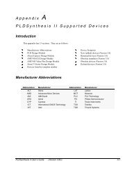
<strong>PALASM</strong> <strong>Synthesis</strong>11. Menu<strong>PALASM</strong> synthesis in <strong>PLS</strong> is obtained by selecting <strong>PALASM</strong> input format inthe Command -> Execute -> Input Format menu. Specific options to <strong>PALASM</strong>format are available through "Source Options" window. The following displaywill appear:<strong>PALASM</strong> <strong>Synthesis</strong> - 31
<strong>PALASM</strong> <strong>Synthesis</strong>12. On-Line ModeTo perform synthesis from <strong>PALASM</strong> format using the On line mode : place thepointer on the "Command " menu in the menu bar of the main <strong>PLS</strong> window andselect "On Line Command". The "On line Command" window will appear.The following parameter have to be defined in the command line :• Encoding option(-c)Value:SEQ for sequential encodingONE for one-hot encoding (recommended for speed optimization)OPT for optimized encodingGRAY for Gray encodingJOHN for Johnson encodingBEST for best encodingRAN for random encoding• Choice of type of the memory elements(-ff)Value:D, T, JK or RSDefault: The default value is D.• Changing edge on the clock signal(-ffsense)Value:Default:RE or FEDefault value is RE.<strong>PALASM</strong> <strong>Synthesis</strong> - 32