Marconi Applied Technologies MG4004 X-Band Magnetron
Marconi Applied Technologies MG4004 X-Band Magnetron
Marconi Applied Technologies MG4004 X-Band Magnetron
- No tags were found...

You also want an ePaper? Increase the reach of your titles
YUMPU automatically turns print PDFs into web optimized ePapers that Google loves.
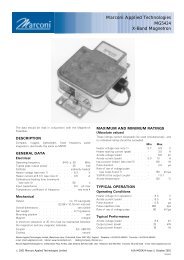
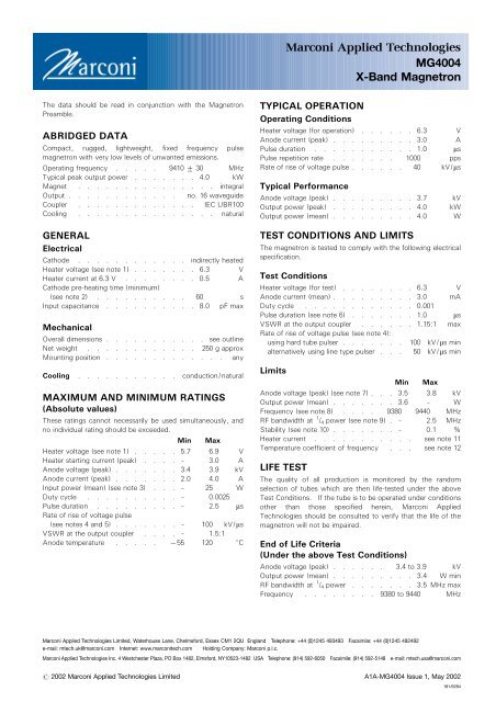
<strong>Marconi</strong> <strong>Applied</strong> <strong>Technologies</strong><strong>MG4004</strong>X-<strong>Band</strong> <strong>Magnetron</strong>The data should be read in conjunction with the <strong>Magnetron</strong>Preamble.ABRIDGED DATACompact, rugged, lightweight, fixed frequency pulsemagnetron with very low levels of unwanted emissions.Operating frequency . . . . . 9410 + 30 MHzTypical peak output power . . . . . . . 4.0 kWMagnet . . . . . . . . . . . . . . . integralOutput . . . . . . . . . . . . no. 16 waveguideCoupler . . . . . . . . . . . . . IEC UBR100Cooling . . . . . . . . . . . . . . . naturalGENERALElectricalCathode . . . . . . . . . . . . indirectly heatedHeater voltage (see note 1) . . . . . . . 6.3 VHeater current at 6.3 V . . . . . . . . 0.5 ACathode pre-heating time (minimum)(see note 2) . . . . . . . . . . 60 sInput capacitance . . . . . . . . . . 8.0 pF maxMechanicalOverall dimensions . . . . . . . . . . . see outlineNet weight . . . . . . . . . . . . 250 g approxMounting position . . . . . . . . . . . . . anyCooling . . . . . . . . . . . conduction/naturalMAXIMUM AND MINIMUM RATINGS(Absolute values)These ratings cannot necessarily be used simultaneously, andno individual rating should be exceeded.Min MaxHeater voltage (see note 1) . . . . . 5.7 6.9 VHeater starting current (peak) . . . . – 3.0 AAnode voltage (peak) . . . . . . . 3.4 3.9 kVAnode current (peak) . . . . . . . 2.0 4.0 AInput power (mean) (see note 3) . . . – 25 WDuty cycle . . . . . . . . . . – 0.0025Pulse duration . . . . . . . . . – 2.5 msRate of rise of voltage pulse(see notes 4 and 5) . . . . . . . – 100 kV/msVSWR at the output coupler . . . . – 1.5:1Anode temperature . . . . . 755 120 8CTYPICAL OPERATIONOperating ConditionsHeater voltage (for operation) . . . . . . 6.3 VAnode current (peak) . . . . . . . . . 3.0 APulse duration . . . . . . . . . . . 1.0 msPulse repetition rate . . . . . . . 1000 ppsRate of rise of voltage pulse . . . . . . 40 kV/msTypical PerformanceAnode voltage (peak) . . . . . . . . . 3.7 kVOutput power (peak) . . . . . . . . . 4.0 kWOutput power (mean) . . . . . . . . . 4.0 WTEST CONDITIONS AND LIMITSThe magnetron is tested to comply with the following electricalspecification.Test ConditionsHeater voltage (for test) . . . . . . . . 6.3 VAnode current (mean) . . . . . . . . . 3.0 mADuty cycle . . . . . . . . . . . . 0.001Pulse duration (see note 6) . . . . . . . 1.0 msVSWR at the output coupler . . . . . . 1.15:1 maxRate of rise of voltage pulse (see note 4):using hard tube pulser . . . . . . . 100 kV/ms minalternatively using line type pulser . . . 50 kV/ms minLimitsMin MaxAnode voltage (peak) (see note 7) . . . 3.5 3.8 kVOutput power (mean) . . . . . . . 3.6 – WFrequency (see note 8) . . . . 9380 9440 MHzRF bandwidth at 1 / 4 power (see note 9) . – 2.5 MHzStability (see note 10) . . . . . . . – 0.1 %Heater current . . . . . . . . . . . see note 11Temperature coefficient of frequency . . . see note 12LIFE TESTThe quality of all production is monitored by the randomselection of tubes which are then life-tested under the aboveTest Conditions. If the tube is to be operated under conditionsother than those specified herein, <strong>Marconi</strong> <strong>Applied</strong><strong>Technologies</strong> should be consulted to verify that the life of themagnetron will not be impaired.End of Life Criteria(Under the above Test Conditions)Anode voltage (peak) . . . . . . 3.4 to 3.9 kVOutput power (mean) . . . . . . . . . 3.4 W minRF bandwidth at 1 / 4 power . . . . . . . 3.5 MHz maxFrequency . . . . . . . . 9380 to 9440 MHz<strong>Marconi</strong> <strong>Applied</strong> <strong>Technologies</strong> Limited, Waterhouse Lane, Chelmsford, Essex CM1 2QU England Telephone: +44 (0)1245 493493 Facsimile: +44 (0)1245 492492e-mail: mtech.uk@marconi.com Internet: www.marconitech.com Holding Company: <strong>Marconi</strong> p.l.c.<strong>Marconi</strong> <strong>Applied</strong> <strong>Technologies</strong> Inc. 4 Westchester Plaza, PO Box 1482, Elmsford, NY10523-1482 USA Telephone: (914) 592-6050 Facsimile: (914) 592-5148 e-mail: mtech.usa@marconi.com# 2002 <strong>Marconi</strong> <strong>Applied</strong> <strong>Technologies</strong> Limited A1A-<strong>MG4004</strong> Issue 1, May 2002181/6284
NOTES1. No reduction of heater voltage is required at any value ofmean input power. For optimum performance a valuewithin the specified ratings must be maintained.The magnetron heater must be protected against arcing bythe use of a minimum capacitance of 4000 pF shuntedacross the heater directly at the input terminals; in somecases a capacitance as high as 2 mF may be necessarydepending on the equipment design. For further details seethe <strong>Magnetron</strong> Preamble.2. For ambient temperatures above 0 8C. For ambienttemperatures between 0 and 755 8C, cathode pre-heatingtime is 75 seconds minimum.3. The various parameters are related by the followingformula:Pi = i apk xv apk xDuwhere Pi = mean input power in wattsi apk = peak anode current in amperesv apk = peak anode voltage in voltsand Du = duty cycle.4. Defined as the steepest tangent to the leading edge of thevoltage pulse above 80% amplitude. Any capacitance inthe viewing system must not exceed 6.0 pF.5. The maximum rate of rise of voltage for stable operationdepends upon detailed characteristics of the applied pulseand the pulser design. The specified maximum ratingapplies to typical hard tube pulsers. For minimum startingjitter and optimum operation, the recommended rate of riseof voltage for most line type pulsers is from 30 to 50 kV/ms.6. Tolerance + 10%.7. Measurements taken ‘as read’ using suitably calibratedequipment.8. Measured at factory ambient. Anode temperature 40 8Capprox.9. Design test only.10. Design test only. With the magnetron operating into aVSWR of 1.15:1 over a peak anode current range of 2.0 to4.0 A. Pulses are defined as missing when the RF energylevel is less than 70% of the normal energy level in a 0.5%frequency range. Missing pulses are expressed as apercentage of the number of input pulses applied during atwo minute period of observation.11. Measured with heater voltage of 6.3 V and no anode inputpower, the heater current limits are 0.5 A minimum, 0.6 Amaximum.12. Design test only. The maximum frequency changewith anode temperature change (after warming) is70.25 MHz/8C.HEALTH AND SAFETY HAZARDS<strong>Marconi</strong> <strong>Applied</strong> <strong>Technologies</strong> magnetrons are safe to handleand operate, provided that the relevant precautions statedherein are observed. <strong>Marconi</strong> <strong>Applied</strong> <strong>Technologies</strong> does notaccept responsibility for damage or injury resulting from the useof electronic devices it produces. Equipment manufacturers andusers must ensure that adequate precautions are taken.Appropriate warning labels and notices must be provided onequipments incorporating <strong>Marconi</strong> <strong>Applied</strong> <strong>Technologies</strong>devices and in operating manuals.High VoltageEquipment must be designed so that personnel cannot comeinto contact with high voltage circuits. All high voltage circuitsand terminals must be enclosed and fail-safe interlock switchesmust be fitted to disconnect the primary power supply anddischarge all high voltage capacitors and other stored chargesbefore allowing access. Interlock switches must not bebypassed to allow operation with access doors open.RF RadiationPersonnel must not be exposed to excessive RF radiation. AllRF connectors must be correctly fitted before operation so thatno leakage of RF energy can occur and the RF output must becoupled efficiently to the load. It is particularly dangerous tolook into open waveguide or coaxial feeders while the device isenergised. Screening of the cathode sidearm of high powermagnetrons may be necessary.X-Ray RadiationHigh voltage magnetrons emit a significant intensity of X-raysnot only from the cathode sidearm but also from the outputwaveguide. These rays can constitute a health hazard unlessadequate shielding for X-ray radiation is provided. This is acharacteristic of all magnetrons and the X-rays emittedcorrespond to a voltage much higher than that of the anode.<strong>MG4004</strong>, page 2# 2002 <strong>Marconi</strong> <strong>Applied</strong> <strong>Technologies</strong>
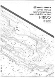
PERFORMANCE CHART6762854MAXIMUMTYPICALPEAK OUTPUT POWER (kW) PEAK ANODE VOLTAGE (kV)3210765432100 1 2 3 4 5PEAK ANODE CURRENT (A)MINIMUMPEAK CURRENTRATING LIMITSTYPICALMINIMUM# 2002 <strong>Marconi</strong> <strong>Applied</strong> <strong>Technologies</strong> <strong>MG4004</strong>, page 3
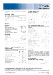
OUTLINE (Not for inspection purposes)(All dimensions without limits are nominal)8079SEE NOTE 3HEATER/CATHODETERMINALHEATER TERMINALBALEAD CONNECTIONTAGS. SEE NOTE 2C4 HOLES 1DSEE NOTE 12 HOLES 1ESEE NOTE 1FFGHHRefMillimetresJOutline Notes1. Positional tolerance 0.4 mm diameter.2. Tags to take wire assembly 300 mm min. long, fitted usingAMP-63837-1 connector, available separately from <strong>Marconi</strong><strong>Applied</strong> <strong>Technologies</strong>.3. Anode temperature measured at this point.4. The mating surface of the magnetron baseplate will be flatto within 0.2 mm.KA 73.0 maxB 42.0 maxC 40.0 max4.39 maxD4.24 min4.52 maxE4.37 minF 15.5G 5.2H 16.26J 20.2 maxK 43.74Whilst <strong>Marconi</strong> <strong>Applied</strong> <strong>Technologies</strong> has taken care to ensure the accuracy of the information contained herein it accepts no responsibility for the consequences of anyuse thereof and also reserves the right to change the specification of goods without notice. <strong>Marconi</strong> <strong>Applied</strong> <strong>Technologies</strong> accepts no liability beyond that set out in itsstandard conditions of sale in respect of infringement of third party patents arising from the use of tubes or other devices in accordance with information contained herein.<strong>MG4004</strong>, page 4Printed in England# 2002 <strong>Marconi</strong> <strong>Applied</strong> <strong>Technologies</strong>