Shear Strength Reduction Approach for Slope Stability Analyses
Shear Strength Reduction Approach for Slope Stability Analyses
Shear Strength Reduction Approach for Slope Stability Analyses
- No tags were found...

You also want an ePaper? Increase the reach of your titles
YUMPU automatically turns print PDFs into web optimized ePapers that Google loves.
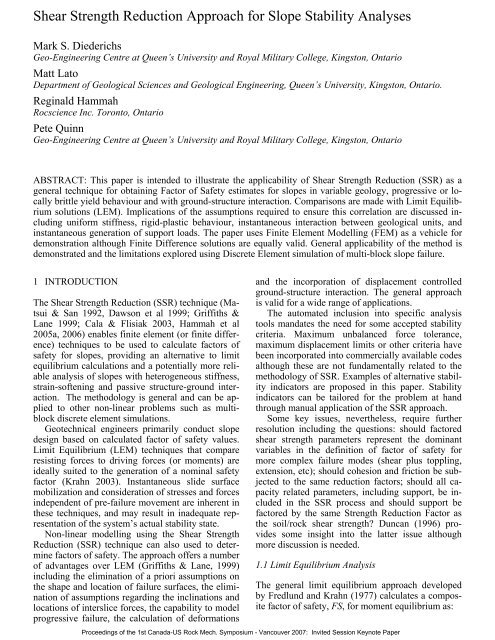
<strong>Shear</strong> <strong>Strength</strong> <strong>Reduction</strong> <strong>Approach</strong> <strong>for</strong> <strong>Slope</strong> <strong>Stability</strong> <strong>Analyses</strong>Mark S. DiederichsGeo-Engineering Centre at Queen’s University and Royal Military College, Kingston, OntarioMatt LatoDepartment of Geological Sciences and Geological Engineering, Queen’s University, Kingston, Ontario.Reginald HammahRocscience Inc. Toronto, OntarioPete QuinnGeo-Engineering Centre at Queen’s University and Royal Military College, Kingston, OntarioABSTRACT: This paper is intended to illustrate the applicability of <strong>Shear</strong> <strong>Strength</strong> <strong>Reduction</strong> (SSR) as ageneral technique <strong>for</strong> obtaining Factor of Safety estimates <strong>for</strong> slopes in variable geology, progressive or locallybrittle yield behaviour and with ground-structure interaction. Comparisons are made with Limit Equilibriumsolutions (LEM). Implications of the assumptions required to ensure this correlation are discussed includinguni<strong>for</strong>m stiffness, rigid-plastic behaviour, instantaneous interaction between geological units, andinstantaneous generation of support loads. The paper uses Finite Element Modelling (FEM) as a vehicle <strong>for</strong>demonstration although Finite Difference solutions are equally valid. General applicability of the method isdemonstrated and the limitations explored using Discrete Element simulation of multi-block slope failure.1 INTRODUCTIONThe <strong>Shear</strong> <strong>Strength</strong> <strong>Reduction</strong> (SSR) technique (Matsui& San 1992, Dawson et al 1999; Griffiths &Lane 1999; Cala & Flisiak 2003, Hammah et al2005a, 2006) enables finite element (or finite difference)techniques to be used to calculate factors ofsafety <strong>for</strong> slopes, providing an alternative to limitequilibrium calculations and a potentially more reliableanalysis of slopes with heterogeneous stiffness,strain-softening and passive structure-ground interaction.The methodology is general and can be appliedto other non-linear problems such as multiblockdiscrete element simulations.Geotechnical engineers primarily conduct slopedesign based on calculated factor of safety values.Limit Equilibrium (LEM) techniques that compareresisting <strong>for</strong>ces to driving <strong>for</strong>ces (or moments) areideally suited to the generation of a nominal safetyfactor (Krahn 2003). Instantaneous slide surfacemobilization and consideration of stresses and <strong>for</strong>cesindependent of pre-failure movement are inherent inthese techniques, and may result in inadequate representationof the system’s actual stability state.Non-linear modelling using the <strong>Shear</strong> <strong>Strength</strong><strong>Reduction</strong> (SSR) technique can also used to determinefactors of safety. The approach offers a numberof advantages over LEM (Griffiths & Lane, 1999)including the elimination of a priori assumptions onthe shape and location of failure surfaces, the eliminationof assumptions regarding the inclinations andlocations of interslice <strong>for</strong>ces, the capability to modelprogressive failure, the calculation of de<strong>for</strong>mationsand the incorporation of displacement controlledground-structure interaction. The general approachis valid <strong>for</strong> a wide range of applications.The automated inclusion into specific analysistools mandates the need <strong>for</strong> some accepted stabilitycriteria. Maximum unbalanced <strong>for</strong>ce tolerance,maximum displacement limits or other criteria havebeen incorporated into commercially available codesalthough these are not fundamentally related to themethodology of SSR. Examples of alternative stabilityindicators are proposed in this paper. <strong>Stability</strong>indicators can be tailored <strong>for</strong> the problem at handthrough manual application of the SSR approach.Some key issues, nevertheless, require furtherresolution including the questions: should factoredshear strength parameters represent the dominantvariables in the definition of factor of safety <strong>for</strong>more complex failure modes (shear plus toppling,extension, etc); should cohesion and friction be subjectedto the same reduction factors; should all capacityrelated parameters, including support, be includedin the SSR process and should support befactored by the same <strong>Strength</strong> <strong>Reduction</strong> Factor asthe soil/rock shear strength? Duncan (1996) providessome insight into the latter issue althoughmore discussion is needed.1.1 Limit Equilibrium AnalysisThe general limit equilibrium approach developedby Fredlund and Krahn (1977) calculates a compositefactor of safety, FS, <strong>for</strong> moment equilibrium as:Proceedings of the 1st Canada-US Rock Mech. Symposium - Vancouver 2007: Invited Session Keynote Paper
( c'βR+ ( N − uβ) R tanφ')Σ( Wx − Nf ) DdFS Σ= M ±(1)and <strong>for</strong> <strong>for</strong>ce equilibrium as:Σ( c'β cosα+ ( N − uβ) tanφ'cosα)FS M= (2)Σ N sinα− Dcos( ) ωwhere the slice base normal <strong>for</strong>ce is:c'β sinα+ uβsinαtanφ'W + ( XR− XL) −N = FS(3)sinαtanφ'cosα+FSwhere u is the pore pressure, W is the slice weight, Dis an applied line load, α is the base inclination andβ, R, x, f, d and ω are geometric parameters.The significant assumptions in this <strong>for</strong>mulationconcern the inter-slice <strong>for</strong>ces (shear and normal).Early techniques (Fellenius 1936) ignored these<strong>for</strong>ces or made significant simplifying assumptions(Janbu 1954, Bishop 1955). Morgenstern and Price(1965) and Spencer (1967) proposed a solution <strong>for</strong>this problem used in the general <strong>for</strong>mulation byFredlund and Krahn (1977). Krahn (2003) summarizesand compares a number of approaches <strong>for</strong>LEM analysis. These differ primarily in the individualor combined consideration of moment or <strong>for</strong>ceequilibrium and the consideration of inter-slice normaland shear <strong>for</strong>ces and the assumed or calculatedinclination of resultant inter-slice <strong>for</strong>ces as illustratedin Figure 1 and summarized in Table 1.Figure 1: Slice and interslice <strong>for</strong>ces <strong>for</strong> a composite limit equilibriumapproach to slope stability.The basal stress state in the original LEM <strong>for</strong>mulationsare ultimately a function of gravitationalloading on the individual slices. This does not considerthe influence of topographical and stiffnessbased variations in the underground stress state.A number of authors, including Zou et al. (1995)and Krahn (2003) have proposed the use of linearelastic finite element analysis to provide the initialstress map <strong>for</strong> a subsequent LEM calculation and theintegration of slice <strong>for</strong>ces. Stianson et al. (2004) investigatethe use of non-linear plastic analysis (<strong>for</strong>stable problems) to compute the basal stress stateand slice <strong>for</strong>ces. These methods collectively representan important advance over conventional techniques.The use of elastic FEM stress calculationstakes into account the stress variability due to stiffnesscontrasts and topography (as in Geo<strong>Slope</strong> 2001,<strong>for</strong> example). The use of plastic analysis to computestresses <strong>for</strong> an LEM calculation may account <strong>for</strong>progressive yield and stress redistribution althoughthe additional complexity of the integrated solutionprocedure is of dubious added value.Another assumption involves the consideration ofline loads in the <strong>for</strong>mulation. Support loading can beconsidered by adjusting resisting <strong>for</strong>ces or driving<strong>for</strong>ces within the factor of safety equation. One approachto handle this problem is to include so-calledactive support (e.g. pre-tensioned anchors) as a reductionto the driving <strong>for</strong>ces while passive anchors(e.g. grouted dowels) are incorporated as an increasein resisting <strong>for</strong>ces. This selection, while logical, issomewhat arbitrary and this challenge is discussed,without the provision of a unique solution, by Krahn(2003). The displacement dependency of resistingloads provided by some passive support systems arenot considered in this <strong>for</strong>mulation.Finally, LEM techniques must be per<strong>for</strong>med on anassumed continuous slip surface. This surface wasoriginally circular in early <strong>for</strong>mulations but mosttechniques after Fellenius can be applied to noncircularand very general surfaces (Figure 2). Thesurface that generates the minimum factor of safetyis located using a grid or optimized search (centerand radius), block search (relocating vertices of anarbitrary slip polygon) or other statistical techniques.For simple geometries, modern searchmethods yield robust results although <strong>for</strong> problemsincluding extreme geometries (very thin weak layers,<strong>for</strong> example), search techniques can often missthe true global minimum (FS) geometry.Table 1: Comparison of equilibrium considerations and interslice <strong>for</strong>ce assumptions (Krahn 2003)MethodMomentEquilibriumHoriz. ForceEquilibriumIntersliceNormal ForceInterslice<strong>Shear</strong> ForceInclination ofInterslice ForceFelleniusBishop SimplifiedJanbu SimplifiedSpencerMorgenstern-PriceCorps of Engin. 1Corps of Engin. 2Lowe-KarafiathYESYESNOYESYESNONONONONOYESYESYESYESYESYESNOYESYESYESYESYESYESYESNONONOYESYESYESYESYESNo ForceHorizontalHorizontalConstantVariable= Crest to Toe Average Dip= Slice Ground Surface Dip= Average of Surface and Base DipProceedings of the 1st Canada-US Rock Mech. Symposium - Vancouver 2007: Invited Session Keynote Paper
ein<strong>for</strong>cement loadings, or shear strain localization(as in Matsui & San 1992) as desired. Figure 4 illustratesthe convergence approach <strong>for</strong> the same slopein Figure 2.Figure 2: a) LEM grid search using SLIDE (RocScience2005a) <strong>for</strong> circular slip surface and b) block search (optimizedvertices). FS
In the supported case, however, the results differin terms of the location of the minimum FS ( =SRF), although the Factor of Safety <strong>for</strong> this newfailure zone falls within the range calculated <strong>for</strong> thiszone in LEM (FS=1.5 to 1.6). The main difference isthat the LEM still locates the minimum surface(FS=1.37-1.46) through the support as in Figure 11.In addition, the lower right plot in Figure 12 illustratesthat the generation of axial load in the supportsis not constant and does not reach the maximumcapacity. The axial (and shear) load developsas the slope de<strong>for</strong>ms. This is more physically accuratethan the assumption of static full capacity (oreven factored nominal capacity) in LEM analysis.In this analysis, however, the capacity of the boltsare not factored along with soil shear strength in theSSR process. There is, at present, no consensus onwhether they should be (i.e. apply the same SSR tobolt capacity) or how the actual loads in the boltsshould be compared with the bolt capacities to givean FS <strong>for</strong> the bolts. This is a discussion that isneeded in order to adopt a standard approach <strong>for</strong>supported slopes. It is possible to use the SSR approachin a different way and discretely select limitingSRF (<strong>for</strong> short and long term stability <strong>for</strong> example)according to accepted practice. This would becompatible with the factored load approach <strong>for</strong>merging structural and geotechnical engineering.The bolts could then be scaled to provide stability<strong>for</strong> the strength-reduced slip surface within a structural(steel code) safety margin. This is just one suggestion.It is clear, however, that more discussion iswarranted on the incorporation of support in SSRmodels. Accepting that SSR is mechanically correct,the accounting process <strong>for</strong> support needs to be furtherdiscussed in the learned community.2.5 Example 5: Stiffness and Strain SofteningThe examples in the previous section were selectedto demonstrate the compatibility of LEM and FEM-SSR techniques <strong>for</strong> simple slope problems. In eachcase the conditions are fixed and the units are of uni<strong>for</strong>mand high stiffness (the correct approach to obtaindirect comparison between the two methods).The following example explores the effect of multiplematerials, stiffness, strain softening and sensitivitiesto convergence tolerance and mesh density.The layer properties (according to Hoek et al. 2002)<strong>for</strong> the example in Figure 13 are given in Table 7.Table 7. <strong>Strength</strong> parameters of the materials in Example 5.UCSMPaUCSresidm i GSI m b s E rmGPaSSt 60 12 21 70 7.2 0.036 16.5Sh1SiltSh215251015251081076065501.92.91.20.0120.0200.0043.09.42.0SSt =Sandstone, Silt =Siltstone, Sh1=shale, Sh2 =weak shaleFigure 13 shows the minimum FS calculated <strong>for</strong>three selected LEM solutions using peak and residualstrength parameters <strong>for</strong> each layer. In this example,the residual strength is specified by reducing thenormalizing UCS. The slope crest is 205m above thelake level.Figure 13: LEM analysis (FS values shown) <strong>for</strong> a stratifiedrock slope. Left analysis uses peak strength from Table 7;Right analysis uses “resid” strength <strong>for</strong> the Sandstone.Figure 14 compares the FEM-SSR results <strong>for</strong>models with elastic-plastic response (using “peak”parameters from Table 7) using identical elasticproperties and variable (true) elastic properties. Theeffect of stiffness contrasts in this case is not particularlysignificant although there is no reason notto include stiffness variation in an FEM-SSR analysis.The results in either case compare best to thenon-circular Bishop analysis in Figure 13.Figure 14: FEM-SSR analysis of slope in Fig. 13 and Table 7.<strong>Shear</strong> strain contours and displacement vectors (x25) plotted.Figure 15 shows the SSR results <strong>for</strong> an analysiswith strain weakening (brittle) behaviour prescribed<strong>for</strong> the sandstone. Other lithologies are plastic. SSRis applied to both peak and residual parameters inthis case.Figure 15: FEM-SSR analysis <strong>for</strong> Example 5 with strain weakeningbehaviour <strong>for</strong> the sandstone (zero dilation). Water tableis solid line (1). <strong>Shear</strong> strain (contours) and displacement vectors(x25) are plotted. Note bimodal failure (2 blocks).Proceedings of the 1st Canada-US Rock Mech. Symposium - Vancouver 2007: Invited Session Keynote Paper
Interestingly, the FS (=SRF=1.85) <strong>for</strong> this analysisis within the range of the LEM analyses <strong>for</strong> residualparameters. In addition, close examination ofFigure 15 shows that both the non-circular, deepseatedslip surface as well as the shallower circularsurface suggested by alternate LEM analyses (rightside of Figure 13) are both simulated in the FEManalysis (two distinct zones of elevated shear strain).The results shown are <strong>for</strong> zero-dilation. Failure geometryis similar <strong>for</strong> dilation (m dil = 0.25m b ) with anelevated FS=SRF=1.92. Table 8 summarizes the impactof mesh density and convergence tolerance.Beyond a reasonable minimum element density, theresults are not very sensitive to mesh configurationalthough poor results are obtained with an elevatedtolerance or the use of 3-noded triangular elements(as opposed to 6-noded linear strain elements).Table 8: Effects of tolerance, maximum iterations per cycleand mesh density <strong>for</strong> Example 5 with brittle sandstone (Figure15) and zero dilation.Mesh Tolerance Max Iterations FS=SRF(*6 nodes)*Standard 0.001 500 1.85*Standard 0.01 250 2.05*Standard 0.0001 1000 1.82*Coarse (x 0.5) 0.001 500 1.86*Fine (x 2) 0.001 500 1.823 node (stand) 0.001 500 2.033 DISCRETE / DISCONTINUOUS MODELSThe application of SSR is not restricted to continuummodels such as finite element or finite differencetools. This section presents two examples ofapplication in discontinuum analysis.3.1 SSR in Discrete Element AnalysisWhile the equilibrium calculation is based on agroup of slices, limit equilibrium techniques stillconsider the behaviour of a contiguous block of rockor soil in a state of limiting sliding instability. Inmulti-block applications, the development of severalunstable blocks and limited movement does notimmediately indicate failure in an operational sense.The example in Figure 16 illustrates the use of SSR<strong>for</strong> a blocky rockmass. The model is created using3DEC and the characterization technique describedby Kalenchuk et al. (2006). A vertical slope is used<strong>for</strong> this simple example. In this model the “actual”joint shear strength properties are specified (cohesoin= 90 kPa, friction angle = 56 deg) although theinitial conditions could be variable and joint specific.The boundary conditions shown are unrealisticand <strong>for</strong> demonstration only. Failure must be definedand could be based on critical displacement or, as inthis case, a limit <strong>for</strong> released blocks or cumulativereleased block volume as shown in Figure 17.Figure 16: Schematic 3DEC block models used in Figure 17.Figure 17: Results of SSR analysis <strong>for</strong> composite model in Figure16. Vertical lines bound the range of FS (=SRF) based ontwo possible failure criteria (see axes). Each point is averagedover several stochastic simulations.3.2 SSR in Discontinuous De<strong>for</strong>mation AnalysisOne of the fundamental premises of the SSR techniqueis that the factor of safety <strong>for</strong> any problem canbe related to the factoring of shear strength <strong>for</strong> materialsand interfaces. Numerous verification examplesillustrate that this gives the same result as an overall<strong>for</strong>ce and moment comparison <strong>for</strong> sliding problems.It is less clear whether the SSR technique is valid <strong>for</strong>problems that do not have a single sliding surfaceand which have internal separation and/or vorticity.The example in Figure 18 demonstrates the applicationof SSR to a simple toppling problem.Figure 18: Example of SSR applied to toppling analysis usingDiscontinuous De<strong>for</strong>mation Analysis. Critical SRF <strong>for</strong> interblockfriction and cohesion <strong>for</strong> this analysis is 1.24. The nominalfriction angle is 30 degrees and the cohesion is 5kPa.Proceedings of the 1st Canada-US Rock Mech. Symposium - Vancouver 2007: Invited Session Keynote Paper
This analysis employs discontinuous de<strong>for</strong>mationanalysis (Sitar et al 2001) assuming that cohesionand friction are the only variables to control stability.The implementation appears simple and reliableenough and reasonable answers can be obtained, althoughit is important to debate the universality ofrelating stability in complex situations (with sliding,extension and rotation) to shear strength alone. Inaddition to the necessary factoring of tensilestrength, crucial in rock mechanics problems, theSSR technique may not adequately capture geometricfactors such as block aspect ratio and rotationalmechanics not related to shear strength. The methodis attractive <strong>for</strong> non-standard applications but themechanics of each case should be compatible.4 CONCLUSIONSFor problems dominated by sliding, the SSR techniquehas been clearly demonstrated as a valid alternativeto Limit Equilibrium Methods. The techniquecan be used in non-linear finite element or finite differencecontinuum models or in discontinuum analysisand is not unreasonably sensitive to model setup(although mesh density, solution tolerance and shapefunction sensitivity must always be checked).The greatest advantage to the SSR technique isthe lack of a requirement to discretely or iterativelypre-define a sliding surface <strong>for</strong> consideration althoughmodern LEM techniques have sophisticatedsearch algorithms <strong>for</strong> non-circular surfaces.In sliding models with no tension crack or with nosupport, the factor of safety can be directly anduniquely related to the factoring of shear strength <strong>for</strong>materials and interfaces giving similar results to anoverall <strong>for</strong>ce and moment comparison (LEM).If tension is involved then tensile strength mustalso be included in the SSR process <strong>for</strong> the geomaterial.It may be necessary to debate the validity ofequal factoring of cohesion and friction in the SSRsolution. Cohesion is often specifed with much lessconfidence than frictional properties and yet <strong>for</strong>shallow problems, dominates over frictional effects.For simple cases the LEM (<strong>for</strong>ce and moment)definition of FS coincides with the SSR (FS=criticalSRF) definition. The definitions deviate <strong>for</strong> morecomplex geologies and material behaviour. <strong>Shear</strong>strength may not be the dominant parametric factorin the true factor of safety in many cases.It is also not clear how shear strength reductionshould be standardized in cases where support is involved.More discussion is needed to decide whethersupport strength be fixed during the SSR iterationsor included in the over all strength reduction.REFERENCESCala M, & Flisiak J. 2003. Complex geology slope stabilityanalysis by shear strength reduction. Proc. of the 3rd Int.FLAC Symp., Sudbury. Lisse: Balkema. 99-102.Dawson EM, Roth WH, Dresher A. 1999. <strong>Slope</strong> stabilityanalysis by strength reduction. Geotechnique, 49(6). 835-840.Duncan, J.M. 1996. State of the art: limit equilibrium and finite-elementanalysis of slopes, Journal of GeotechnicalEngineering, 122(7). 577-596.Fellenius W. 1936. Calculation of the stability of earth dams.2 nd Congress on Large Dams. Washington. V4. p445.Fredlund DG & Krahn J. 1977. Comparison of slope stabilitymethods of analysis. Can. Geotech. J. v14. 429-439.Geo-<strong>Slope</strong>. 2001. SLOPEW v5. <strong>Slope</strong> stability analysis.Giam PSK & Donald IB. 1989. Example problems <strong>for</strong> testingsoil slope stability programs. Civil Engineering ResearchReport No. 8/1989. Monash University.Griffiths DV, Lane PA. 1999. <strong>Slope</strong> stability analysis by finiteelements. Geotechnique. 49(3). 387-403Hammah RE, Yacoub TE, & Curran JH. 2006. Investigatingthe per<strong>for</strong>mance of the shear strength reduction (SSR)method on the analysis of rein<strong>for</strong>ced slopes. In Proceedingsof the 59th Canadian Geotechnical Conference, Vancouver.Hammah RE, Yacoub TE, Corkum B & Curran JH. 2005a. Acomparison of finite element slope stability analysis withconventional limit-equilibrium investigation. In Proceedingsof the 58th Can. Geotech. Conference, Saskatoon.Hammah RE, Yacoub TE, Corku, B & Curran J. 2005b. The<strong>Shear</strong> <strong>Strength</strong> <strong>Reduction</strong> Method <strong>for</strong> the GeneralizedHoek-Brown Criterion. Alaska Rocks: 40th U.S. Symposiumon Rock Mechanics. Paper 05-810. 6pgs.Hoek E, Carranza-Torres CT, Corkum B. 2002. Hoek-Brownfailure criterion-2002 edition. In: 5th North American rockmechanics symposium, Toronto, Canada, vol. 1. 267–73.Itasca. 3DEC v3. 200a 3-Dimensional distinct element code.Itasca. FLAC/FLAC-SLOPE. 2003b. Fast Lagrangian Analysisof Continua – <strong>Slope</strong> modelling package.Janbu N. 1954. Application of composite slip surfaces <strong>for</strong> stabilityanalysis. Proc. European Conf. on the <strong>Stability</strong> ofEarth <strong>Slope</strong>s. V3. p39-43.Kalenchuk, K. , Diederichs, M.S. and McKinnon, S. 2006.Characterizing block geometry in jointed rockmasses. IntJour of Rock Mech. & Min. Sc.. 43(8) , pg 1212-1225.Krahn J. 2003. The 2001 R.M. Hardy Lecture: The limits oflimit equilibrium analysis. Can. Geotech. J. v40. 643-660.Lorig L., & Varona P. 2004. Numerical Analysis. in Rock<strong>Slope</strong> Engineering, pp. 218-244, D. C. Wyllie and C. W.Mah, Eds. London: Spon Press.Matsui T & San KC. 1992. Finite element slope stability analysisby shear strength reduction technique. Soils and Foundations.32(1). 59-70.Morgenstern NR & Price VE. 1965. The analysis of the stabilityof general slip surfaces. Geotechnique 15(1). 79-93.Rocscience Inc. 2005a. SLIDE v5 – Software <strong>for</strong> 2D Limit-Equlibrium Analysis <strong>for</strong> soil and rock slopes.Rocscience Inc. 2005b PHASE2 v6 Elasto-plastic finite elementstress analysis software.Sitar N, MacLaughlin MM, Doolin DM & Abbot T. 2001. Investigationof slope stability kinematics using discontinuousde<strong>for</strong>mation analysis. Int. Jour. of Rock Mech. andMin. Sci. v. 38, pp. 753-762,Spencer, E. 1967. A method of analysis of embankments assumingparallel interslice <strong>for</strong>ces. Geotechnique.17(1) 11-26Stianson JR, Chan D & Fredlund DG. 2004. Comparing slopestability analysis based on linear elastic or elasto-plasticstresses using dynamic programming techniques. 57 th Can.Geotech Conf. Session 7C. p23-30.Zou JZ, Williams DJ and Xiong WL. 1995. Search <strong>for</strong> criticalslip surfaces based on finite element method. Can. Geotech.J. 32(2) 233-246.Proceedings of the 1st Canada-US Rock Mech. Symposium - Vancouver 2007: Invited Session Keynote PaperBishop AW. 1955. The use of the slip circle <strong>for</strong> the stabilityanalysis of slopes. Geotechnique. 5(1) 7-17.