YUKEN Hydraulic Equipment
YUKEN Hydraulic Equipment
YUKEN Hydraulic Equipment
- No tags were found...

You also want an ePaper? Increase the reach of your titles
YUMPU automatically turns print PDFs into web optimized ePapers that Google loves.
CPRESSURE CONTROLSValve TypeGraphic SymbolsMaximumOperatingPressureMPa(PSI)Maximum FlowU.S.GPM.5 1 2 5 10 20 50 100 200 5001 2 3 5 10 20 30 50 100 200 300 500 1000 2000L/minPageRemote Cont.Relief Valves25(3630)DTDG01203Direct TypeRelief Valves21(3050)DT/DG02206Pilot OperatedRelief Valves25(3630)BT/BG030610209Low Noise TypePilot OperatedRelief Valves25(3630)S-BG030610216Sol. Cont.Relief ValvesLow Noise TypeSol. Cont.Relief Valves25(3630)25(3630)S-BSGBST/BSG030306061010220230H TypePress. Cont. Valves /HC TypePress. Cont. ValvesPress. Reducing Valves /Press. Reducing& Check ValvesPres. Reducing& Relieving Valves21(3050)21(3050)03 : 14(2030)06 : 25(3630)HT/HGHCT/HCGRT/RGRCT/RCGRBG0303030606061010HFHCF 16RF 16RCF237251260UnloadingRelief Valves21(3050)BUCG 06 10265Brake ValvesT25(3630)UBGR030610271Semiconductor TypePressure Switches35(5080)JT-02272Pressure Monitoring System20(2900)35(5080)274201
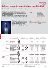
PRESSURE CONTROLSRemote Control Relief ValvesThis valve is used as a remote control valve for pilot operated typepressure control valves.SpecificationsThreadedConnectionDT-01-22 *Model NumbersSub-plateMountingDG-01-22 *Max. Operating Pres.MPa (PSI)25 (3630)Approx. Masskg (lbs.)DT type DG type1.6 (3.5) 1.4 (3.1)CModel Number DesignationF-DSpecial Seals Series NumberTType ofMounting-01Valve Size-22 *DesignNumberDesign StandardsRemote ControlRelief ValvesF:Special Sealsfor PhosphateEster TypeFluids(Omit if notrequired)D:Remote ControlRelief ValvesT: ThreadedConnectionG: Sub-plateMounting012222None: Japanese Std. "JIS"80: European Design Std.90: N. American Design Std.None: Japanese Std. "JIS" andEuropean Design Std.90: N. American Design Std.InstructionsTo adjust the pressure, loosen the lock nut and turn the handle slowly clockwise for higherpressures or anti-clockwise for lower pressures. After adjustments, do not forget to tightenthe lock nut.Piping of the tank line should not be connected to any tank line of the other valves, butconnected directly to the reservoir.Pressure is limited by collars fitted. If a working pressure cannot be attained,remove some collars. One collar is equivalent to 10 MPa (1450 PSI).If the internal volume of the vent line is too large, chattering is likely to occur.Graphic SymbolAttachmentMounting boltsValve ModelSocket Head Cap ScrewQty.NumbersJapanese Std. "JIS" and European Design Std.N. American Design Std.DG-01 M5 45 Lg.No.10-24 UNC 1-3/4 Lg. 4Sub-plateValve ModelNumbersJapanese Standard "JIS" European Design Standard N. American Design StandardSub-plateModel NumbersThreadSizeSub-plateModel NumbersApprox.Masskg (lbs.)DG-01DGM-02-20 Rc 1/4 DGM-02-2080 1/4 BSP.F DGM-02-2090 1/4 NPT 0.7 (1.5)Sub-plates are available. Specify the sub-plate model number from the table above. When sub-plates are not used, the mounting surface should have agood machined finish.ThreadSizeSub-plateModel NumbersThreadSizeRemote Control Relief Valves203
DT-01-22/2280/2290Lock Nut 14(.55) Hex.DIMENSIONS INMILLIMETRES (INCHES)Two Collars52(2.05)26(1.02)Model NumbersDT-01-22"A" Thd.Rc 1/450(1.97)DT-01-2280DT-01-22901/4 BSP.F1/4 NPTFully Extended193(7.60)141.5(5.57)Pressure AdjustmentHandleINC.Dimensions ofThe Panel Mounting HoleMax.10(.39)47(1.85)26(1.02)44(1.73)Dia.21(.83)Dia.Pressure Port"A" Thd.74(2.91)Tank Port "A" Thd.Lock Nut 24(.94) Hex.DG-01-22/2290Sub-plate: DGM-02-20/2080/20907(.28)19(.75)30(1.18)5.5(.22) Dia. Through9(.35) Dia. Spotface4 Places60(2.36)Lock Nut 14(.55) Hex.Two Collars50(1.97)30(1.18)27(1.06)15(.59)2(.08)10(.39)6.2(.24) Dia."A" Thd. (From Rear)2 Places7.5(.30)24(.94)17(.67)14(.55)52(2.05)52(2.05)38(1.50)44(1.73)Dia.13.5(.53)Pressure PortTank Port50(1.97)10(.39)19(.75)38(1.50)65(2.56)80(3.15)Fully Extended142.5(5.61)100(3.94)Pressure AdjustmentHandleINC."B" Thd. 10(.39) Deep4 Places47(1.85)38(1.50)37(1.46)26(1.02)48(1.89)7(.28) Dia. Through11(.43) C' bore2 PlacesMounting Surface(O-Rings Furnished)Model Numbers"A" Thd."B" Thd.DGM-02-20DGM-02-2080Rc 1/41/4 BSP.FM5DGM-02-20901/4 NPTNo. 10-24 UNC204Remote Control Relief Valves
PRESSURE CONTROLSSpare Parts ListDT-01-22/2280/229012 2 3 4 15 11 6 8 71 5 13 14 10 9List of SealsItem1314Name of PartsO-RingO-RingPart NumbersSO-NA-P12SO-NB-P22.4Qty.11Note: When ordering the seals, please specify the seal kitnumber from the table below.CRemote ControlRelief ValvesList of Seal KitsValve Model NumbersDT-01DG-01Seal Kit NumbersKS-DT-01-22KS-DG-01-22DG-01-22/229013 2 1 3 10 14 6 9 8 7List of SealsItem Name of Parts Part Numbers Qty.1112O-RingO-RingSO-NA-P9SO-NB-P912Note: When ordering the seals, please specify the seal kitnumber from the table above.12 4 11 5Remote Control Relief Valves205
Direct Type Relief ValvesThis valve is used in a hydraulic circuit to prevent damage due toover pressure and to adjust the maximum circuit pressure of smallcapacity.SpecificationsModel NumbersThreadedConnectionSub-plateMountingMax. OperatingPressureMPa (PSI)Pres. Adj.RangeMPa (PSI)Max. FlowL/minApprox. Masskg (lbs.)(U.S.GPM) DT type DG type16(4.23)1.5 (3.3)DT-02- * -22 * DG-02- * -22 * 21 (3050) Note) 1.5 (3.3)Note: Refer to the Model Number Designation.Model Number DesignationF-Special SealsF:Special Sealsfor PhosphateEster TypeFluids(Omit if notrequired)DSeries NumberD:Direct TypeRelief ValvesTType ofMountingT: ThreadedConnectionG: Sub-plateMountingRefer to the Minimum Adjustment Pressure Characteristics.-02Valve Size02-B -22*Pres. Adj. RangeMPa (PSI)B: -7( -1020)C: 3.5-14(510-2030)H: 7-21(1020-3050)DesignNumber2222Design StandardsNone: Japanese Std. "JIS"80: European Design Std.90: N. American Design Std.None: Japanese Std. "JIS" andEuropean Design Std.90: N. American Design Std.InstructionsTo adjust the pressure, loosen the lock nut and turn the handle slowly clockwise for higherpressures or anti-clockwise for lower pressures. After adjustments, do not forget to tightenthe lock nut.Piping of the tank line should not be connected to any tank line of the other valves, butconnected directly to the reservoir.Graphic SymbolAttachmentMounting boltsValve ModelSocket Head Cap ScrewQty.NumbersJapanese Std. "JIS" and European Design Std.N. American Design Std.DG-02 M5 45 Lg.No.10-24 UNC 1-3/4 Lg.4Sub-plateValve ModelNumbersDG-02Japanese Standard "JIS" European Design Standard N. American Design StandardSub-plateModel NumbersThreadSizeSub-plateModel NumbersThreadSizeSub-plateModel NumbersThreadSizeApprox.Masskg (lbs.)DGM-02-20 Rc 1/4 DGM-02-2080 1/4 BSP.F DGM-02-2090 1/4 NPT 0.7 (1.5)Sub-plates are available. Specify the sub-plate model number from the table above. When sub-plates are not used, the mounting surface should have agood machined finish.The sub-plates are those for remote control relief valves. For dimensions, see page 204.206Direct Type Relief Valves
PRESSURE CONTROLSMin. Adjustment PressureMin. Adjustment PressurePSI1751501251007550250MPa1.21.00.80.60.40.200 2 4 6 8 10 12 14 16 L/min0 1 2 3 4 U.S. GPMFlow RateDT-02-* -22/2280/2290PSI3000Lock Nut 14(.55) Hex.Nominal Override CharacteristicsPressure250020001500MPa17.5DT-02-HDG-02-H14.010.5DT-02-CDG-02-C7.0DT-02-B3.5DG-02-B00 2 4 6 8 10 12 14 16 L/min0 1 2 3 4 4.5 U.S. GPMFlow RateCDirect TypeRelief Valves52(2.05)26(1.02)50(1.97)Model NumbersDT-02- * -22DT-02- * -2280DT-02- * -2290"A" Thd.Rc 1/41/4 BSP.F1/4 NPTPressure Port"A" Thd.Fully Extended163(6.42)112(4.41)Pressure AdjustmentHandleINC.Max.10(.39)47(1.85)26(1.02)44(1.73)Dia.21(.83)Dia.74(2.91)Lock Nut 24(.94) Hex.Tank Port "A" Thd.7DIMENSIONS INMILLIMETRES (INCHES)52(2.05)19(.75)5.5(.22) Dia. Through9(.35) Dia. Spotface4 PlacesLock Nut14(.55) Hex.44(1.73)Dia.Pressure Port50(1.97)10(.39)Tank PortFully Extended160(6.42)100(3.94)Pressure AdjustmentHandleINC.47(1.85)38(1.50)26(1.02)48(1.89)1000500021.0<strong>Hydraulic</strong> fluid2Viscosity : 35 mm /s (164 SSU)Specific Gravity : 0.850Dimensions ofThe Panel Mounting HoleDG-02-* -22/229037(1.46)(.28)Mounting Surface(O-Rings Furnished)Note: For dimensions of the valve mounting surface, seethe dimensional drawing (page 204) of the subplateused together.Direct Type Relief Valves207
Spare Parts ListDT-02-* -22/2280/2290DG-02-* -22/2290 12 13 1410 2 3 11 1 9 5 6 7 84List of SealsItem Name of Parts Part Numbers Qty. Remarks121314O-RingO-RingO-RingSO-NB-P9SO-NA-P12SO-NB-P22.4211Use only for DG-02Note: When ordering the seals, please specify the seal kit number from the table below.List of Seal KitsValve Model NumbersDT-02DG-02Seal Kit NumbersKS-DT-01-22KS-DG-02-22208Direct Type Relief Valves
PRESSURE CONTROLSPilot Operated Relief ValvesThese valves protect the hydraulic system from excessive pressure, and can be used to maintain constant pressure in ahydraulic system. Remote control and unloading are permitted by using vent circuits.Graphic SymbolsCVent ConnectionPilot OperatedRelief ValvesSpecificationsThreadedConnectionModel NumbersSub-plateMountingBT-03- * -32 * BG-03- * -32 *BT-06- * -32 * BG-06- * -32 *BT-10- * -32 * BG-10- * -32 *Max. OperatingPressureMPa (PSI)25 (3630)Pres. Adj.RangeMPa (PSI)Note)-25( -3630)Max. FlowL/min(U.S.GPM)100(26.4)200(52.8)400(106)Approx. Masskg (lbs.)BT type5.0(11.0)5.0(11.0)8.5(18.7)BG type4.7(10.4)5.6(12.3)8.7(19.2)Note: Refer to the Minimum adjustment Pressure characteristics on page 214.Model Number DesignationF-BSpecial SealsF:Special Sealsfor PhosphateEster TypeFluids(Omit if notrequired)Series NumberB:Pilot OperatedRelief ValvesTType ofMountingT: ThreadedConnectionG:Sub-plateMounting-03ValveSize030610030610-V -32*High VentingPres. FeatureV:For HighVentingPressureFeature(Omit if notrequired)Use high venting pressure type to reduce the response time from unload to onload.DesignNumber323232323232Design StandardsNone: Japanese Std. "JIS"80: European Design Std.90: N. American Design Std.None: Japanese Std. "JIS" andEuropean Design Std.90: N. American Design Std.Pilot Operated Relief Valves209
PRESSURE CONTROLSBT-03-* -32/3280/3290BT-06-* -32/3280/3290BT-10-* -32/3280/3290DIMENSIONS INMILLIMETRES (INCHES)Lock Nut 14(.55) Hex.Two CollarsC"A" SQ.Vent Port"T" Thd.5(.20)3280 Design OnlyBFully Extended CFour positions of pressure adjustment handleare available by rotating cover assembly as shown.Pressure AdjustmentHandleINC.Pilot OperatedRelief ValvesDF44(1.73)Dia.HLKJPressure Port"S" Thd. 2 PlacesPTTank Port"S" Thd.EPressure Gauge Connection"U" Thd.QNThere are two threaded connection pressure ports. They can be connected each other in-line; one as inlet and the otheras an outlet or the valve can be used by plugging one of the pressure ports.Model NumbersADimensions mm (Inches)B C D E F H J K L N QBT-03- * -32/3280/329075BT-06- * -32/3280/3290 (2.95)BT-10- * -32/3280/329085(3.35)40(1.57)50(1.97)105(4.13)101(3.98)52(2.05)80(3.15)78(3.07)96(3.78)150.5(5.93)183(7.20)68.5(2.70)89(3.50)62(2.44)74(2.91)36(1.42)49(1.93)52(2.05)80(3.15)90(3.54)120(4.72)45(1.77)60(2.36)Model NumbersBT-03- * -32BT-03- * -3280BT-03- * -3290BT-06- * -32BT-06- * -3280BT-06- * -3290BT-10- * -32BT-10- * -3280BT-10- * -3290Thread Size"S" Thd. "T" Thd. "U" Thd.Rc 3/83/8 BSP.F3/8 NPTRc 3/43/4 BSP.F3/4 NPTRc 1-1/41-1/4 BSP.F1-1/4 NPTRc 3/83/8 BSP.F3/8 NPTRc 3/83/8 BSP.F3/8 NPTRc 3/83/8 BSP.F3/8 NPTRc 1/41/4 BSP.Tr1/4 NPTRc 1/41/4 BSP.Tr1/4 NPTRc 1/41/4 BSP.Tr1/4 NPTPilot Operated Relief Valves211
BG-03-* -32/3290BG-06-* -32/3290BG-10-* -32/3290DIMENSIONS INMILLIMETRES (INCHES)Mounting Surface(O-Rings Furnished)Lock Nut 14(.55) Hex.Two Collars"A" SQ.Three positions of pressure adjustment handleare available by rotating cover assembly as shown.Pressure Adjustment HandleBFully Extended CINC.Vent PortLocating Pin6(.24) Dia.44(1.73)Dia.Pressure Gauge Connection"X" Thd.NHQ6(.24)PPressure PortUDVEFTank PortLKJ"S" Dia. Through"T" Dia. Spotface4 PlacesModel NumbersBG-03- * -32/3290 75(2.95)BG-06- * -32/3290 75(2.95)BG-10- * -32/329085(3.35)40(1.57)40(1.57)45(1.77)105(4.13)105(4.13)101(3.98)57(2.24)40(1.57)47(1.85)78(3.07)60(2.36)67(2.64)78(3.07)78(3.07)87.5(3.44)137(5.39)161(6.34)195(7.68)Dimensions mm (Inches)A B C D E F H J K L N P Q S T U V14.1(.56)17(.67)20.7(.81)41(1.61)52(2.05)62(2.44)82(3.23)104(4.09)124(4.88)117(4.61)141(5.55)175(6.89)77(3.03)83.5(3.29)110(4.33)22(.87)4.5(.18)6(.24)13.5(.53)17.5(.69)21.5(.85)21(.83)26(1.02)32(1.26)55(2.17)38(1.50)45(1.77)77(3.03)58(2.28)65(2.56)Model NumbersBG-03- * -32BG-03- * -3290BG-06- * -32BG-06- * -3290BG-10- * -32BG-10- * -3290Thread Size"X" ThdRc 1/4 = 1/4 BSP.Tr1/4 NPTRc 1/4 = 1/4 BSP.Tr1/4 NPTRc 1/4 = 1/4 BSP.Tr1/4 NPTMounting SurfaceISO 6264-AR-06-2-AISO 6264-AS-08-2-AISO 6264-AT-10-2-A212Pilot Operated Relief Valves
PRESSURE CONTROLSBGM-03,03X-20 / 3080 / 2090BGM-06,06X-20 / 3080 / 2090BGM-10,10X-20 / 3080 / 2090DIMENSIONS INMILLIMETRES (INCHES)"d" Dia. Through"e" Dia. Spotface4 Places"h"4 PlacesJABDFEC"t" Thd.6.2(.24) Dia.ZaCYXUSQVTHKLNP7(.28) Dia. 10(.39) Deep "n" Thd. 2 Places(From Rear)"b" Dia.2 PlacesfPilot OperatedRelief ValvesModel NumbersBGM-03BGM-03XBGM-06BGM-06XBGM-10BGM-10XModel NumbersBGM-03BGM-03XBGM-06BGM-06XBGM-10BGM-10XDimensions mm (Inches)A B C D E F H J K L N P Q S86(3.39)108(4.25)126(4.96)60(2.36)78(3.07)94(3.70)13(.51)15(.59)16(.63)53.8(2.12)70(2.76)82.6(3.25)3.1(.12)4(.16)5.7(.22)26.9(1.06)35(1.38)41.3(1.63)149(5.87)180(7.09)227(8.94)13(.51)15(.59)16(.63)123(4.84)150(5.91)195(7.68)86(3.39)95(3.74)106.5(4.19)119(4.69)138.2(5.44)158(6.22)32(1.26)51(2.01)62(2.44)Dimensions mm (Inches)T U V X Y Z a b d e f19(.75)37(1.46)42(1.65)47.4(1.87)55.5(2.19)76.2(3.00)0(0)23.8(.94)31.8(1.25)22(.87)33.4(1.31)44.5(1.75)22(.87)11(.43)12.7(.50)32(1.26)40(1.57)40(1.57)50(1.97)50(1.97)63(2.48)20(.79)25(.98)32(1.26)14.5(.57)23(.91)28(1.10)11(.43)13.5(.53)17.5(.69)17.5(.69)21(.83)26(1.02)19(.75)24(.94)31(1.22)26(1.02)21(.83)27.2(1.07)18(.71)30.2(1.19)17(.67)97(3.82)121(4.76)154(6.06)53.8(2.12)66.7(2.63)88.9(3.50)ModelNumbersBGM-03BGM-03XBGM-06BGM-06XBGM-10BGM-10XJapanese Standard "JIS"Design "20"European Design StandardDesign "3080"N. American Design StandardDesign "2090""h" "n" Thd. "t" Thd. "h" "n" Thd. "t" Thd. "h" "n" Thd. "t" Thd.Rc 3/8Rc 1/2M12 Thd.20(.79) Deep3/8 BSP.F1/2 BSP.F1/2-13UNC Thd.22(.87) Deep3/8 NPT1/2 NPTRc 3/4M16 Thd. 3/4 BSP. F5/8-11UNC Thd. 3/4 NPTRc 1/4 1/4 BSP.FRc 125(.98) Deep 1 BSP.F27(1.06) Deep 1 NPT1/4 NPTRc1-1/4Rc 1-1/2M20 Thd.28(1.10) Deep1-1/4 BSP.F1-1/2 BSP.F3/4-10UNC Thd.28(1.10) Deep1-1/4 NPT1-1/2 NPTM12 Thd.20(.79) DeepM16 Thd.25(.98) DeepM20 Thd.28(1.10) DeepPilot Operated Relief Valves213
Nominal Override CharacteristicsPressure PressureBT-03, BG-03PSI3600330023002000225150PSI3600330023002000300200MPa2524231615141.61.31.0BT-10, BG-10MPa2524231615142.01.61.20 25 50 75 100 L/min0 5 10 15 20 25 U.S. GPMFlow Rate0 100 200 300 400 L/minPressurePSI3600330023002000275200<strong>Hydraulic</strong> fluid: Viscosity : 35 mm /s (164 SSU)Specific Gravity : 0.850BT-06, BG-06MPa2524231615141.91.61.30 50 100 150 200 L/min0 10 20 30 40 50 U.S. GPMFlow Rate20 25 50 75 100 U.S. GPMFlow RateMin. Adj. Pressure & Vent Pressure vs. FlowPressureBT-03, BG-03PSI MPa1008060402000.70.60.4Vent PressureMin. Adjustment Pressure0.20Low VentingHigh Venting Pressure TypePressure Type0 25 50 75 100 L/min0 5 10 15 20 25 U.S. GPMFlow RatePressurePSI200150100500<strong>Hydraulic</strong> fluid: Viscosity : 35 mm /s (164 SSU)Specific Gravity : 0.850BT-06, BG-06MPa1.41.20.8High VentingPressure TypeVent PressureMin. Adjustment Pressure0.4Low Venting0Pressure Type0 50 100 150 200 L/min0 10 20 30 40 50 U.S. GPMFlow Rate2PressureBT-10, BG-10PSI MPa225 1.62001.21500.8100High VentingPressure TypeVent PressureMin. Adjustment Pressure5000.4Low Venting0Pressure Type0 100 200 300 400 L/min0 25 50 75 100 U.S. GPMFlow Rate214Pilot Operated Relief Valves
PRESSURE CONTROLSSpare Parts ListBT-03-* -32/3280/3290BT-06-* -32/3280/3290BT-10-* -32/3280/329018 22 6 7 8 2 16 9 10 11 13 12CAList of Seals1714534212015191Item161724Name of PartsO-RingO-RingBonded SealPart NumbersBT-03 BT-06 BT-10SO-NA-P9 SO-NA-P9SO-NB-P32 SO-NB-P42SG-FB-3/8 SG-FB-3/8Qty.Note: When ordering the seals, please specify the seal kit number from thetable below.111Pilot OperatedRelief ValvesList of Seal Kits2423Section "A"for Design 3280Valve Model Numbers Seal Kit NumbersBT-03KS-BT-03-32BT-06BT-10KS-BT-10-32Note: No bonded seals are included in the seal kits.BG-03-* -32/3290BG-06-* -32/3290BG-10-* -32/329021 16 6 7 8 2 17 9 10 11 13 122018141953244252315221List of SealsItem Name of Parts17 O-Ring18 O-Ring19 O-Ring20 O-RingPart NumbersQty.BG-03 BG-06 BG-10SO-NA-P9 SO-NA-P9SO-NB-P9 SO-NB-P11SO-NB-P18 SO-NB-P28SO-NB-P32 SO-NB-P32SO-NA-P9 1SO-NB-P9 1SO-NB-P32 2SO-NB-P42 1Note: When ordering the seals, please specify the seal kit number from thetable below.List of Seal KitsValve Model NumbersBG-03BG-06BG-10Seal Kit NumbersKS-BG-03-32KS-BG-06-32KS-BG-10-32Pilot Operated Relief Valves215
Low Noise Type Pilot Operated Relief ValvesPilot operated relief valves here have been particularly developed as low-noise types. Able to protect pumps and controlvalves against excessive pressures, they are used to control the pressure in the hydraulic system to a constant level.Remote control and unloading are permitted by using vent circuits.Graphic SymbolsVent ConnectionSpecificationsModel NumbersMax. OperatingPressureMPa (PSI)Pres. Adj.RangeMPa (PSI)Note)-25( -3630)Max. FlowL/min(U.S.GPM)S-BG-03- * - * -40 * 100 (26.4)S-BG-06- * - * -40 * 25 (3630)200 (52.8)S-BG-10- * -40 *400 (106)Note: See minimum adjustment pressure characteristics on page 218.Approx.Masskg (lbs.)4.1 (9.0)5.0 (11.0)10.5 (23.2)Model Number DesignationF- S- BSpecial SealsLow NoiseTypeSeriesNumberGType ofMounting-03ValveSize-V -LHigh VentingPres. Feature1Directionof Handle-40DesignNumber*Design Std.F:Special Seals forPhosphate EsterType Fluids(Omit if notrequired)S:Low NoiseTypeB:PilotOperatedReliefValvesG:Sub-plateMounting030610V:For High VentingPressure Feature(Omit if notrequired)Viewed from pressuregauge connectionL: Left (Normal) R: Right404040Refer to21. Use the high venting pressure type where it is necessary to reduce the response time from unloading to onloading.2. Design Standards: None ........... Japanese Standard "JIS" and European Design Standard90 ............... N. American Design StandardSub-plateValveModelNumbersS-BG-03S-BG-06S-BG-10Japanese Standard "JIS" European Design Standard N. American Design StandardSub-plateModel NumbersBGM-03-20BGM-03X-20BGM-06-20BGM-06X-20BGM-10-20BGM-10X-20ThreadSizeRc 3/8Rc 1/2Rc 3/4Rc 1Rc 1-1/4Rc 1-1/2Sub-plateModel NumbersBGM-03-3080BGM-03X-3080BGM-06-3080BGM-06X-3080BGM-10-3080BGM-10X-3080ThreadSize3/8 BSP.F1/2 BSP.F3/4 BSP.F1 BSP.F1-1/4 BSP.F1-1/2 BSP.FSub-plateModel NumbersBGM-03-2090BGM-03X-2090BGM-06-2090BGM-06X-2090BGM-10-2090BGM-10X-2090ThreadSize3/8 NPT1/2 NPT3/4 NPT1 NPT1-1/4 NPT1-1/2 NPTApprox.Masskg (lbs.)2.4 (5.3)3.1 (6.8)4.7 (10.4)5.7 (12.6)8.4 (18.5)10.3 (22.7)Sub-plates are available. Specify the sub-plate model number from the table above. When sub-plates are not used, the mounting surface should have agood machined finish.The sub-plates are those for pilot operated relief valves. For dimensions, see page 213.216Low Noise Type Pilot Operated Relief Valves
PressureNominal Override CharacteristicsPSI37003500330022001900S-BG-03 S-BG-06 S-BG-1025050MPa2524231514131.51.00.5PressurePSI3700350033002200190025050MPa2524231514131.51.00.5PressurePSI36003400320022001900300150MPa252423221514132.01.51.0<strong>Hydraulic</strong> fluid:2Viscosity : 35 mm /s (164 SSU)Specific Gravity : 0.8500 20 40 60 80100 0 50 100 150 200L/minL/min0 100 200 300 400L/min0 5 10 15 20 25U.S. GPMFlow Rate0 10 20 30 40 50U.S. GPMFlow Rate0 25 50 75 100Flow RateU.S. GPMPressureMin. Adj. Pressure and Vent Pressure vs. FlowPSI120100806040200MPa0.9High Vent0.8Pressure Type0.70.60.50.4Low Vent0.3Pressure Type0.20.100 20 40 60 80 100 L/min0 5 10 15 20Flow Rate25U.S. GPMPressurePSI200150100500MPa1.41.21.00.80.60.4High VentPressure TypeVent PressureMin. Adjustment PressureS-BG-03 S-BG-06 S-BG-100.2Low Vent0Pressure Type0 50 100L/min0 10 20 30 40 50Flow RateU.S. GPMPSI MPa225 1.6200 1.41.2150 High Vent1.0Pressure Type0.81000.650 0.40.2Low Vent00Pressure Type150 2000 100 200 300 400Pressure<strong>Hydraulic</strong> fluid:2Viscosity : 35 mm /s (164 SSU)Specific Gravity : 0.850L/min0 25 50 75 100U.S. GPMFlow RateNoise LevelMeasuring conditionMeasuring position: At 1m (3.3 ft.) back from the valve front.2Viscosity : 35 mm /s (164 SSU)Back pressure : 0.1 MPa (14.5 PSI)S-BG-03 S-BG-06 S-BG-10dB(A)80Flow rate : 50 L/min(13.2 U.S.GPM)dB(A)80Flow rate : 150 L/min(39.6 U.S.GPM)dB(A)80Flow rate : 200 L/min(52.8 U.S.GPM)Noise Level706050Noise Level706050Noise Level706050400 4 8 12 16 20 MPa400 4 8 12 16 20 MPa400 4 8 12 16 20 MPa0 1000 2000Pressure3000 PSI0 1000 2000Pressure3000 PSI0 1000 2000Pressure3000 PSI218Low Noise Type Pilot Operated Relief Valves
PRESSURE CONTROLSSpare Parts ListS-BG-03,06,10-* -40/409013142212201110 26 23 24 15 7 21891922523219C3031List of Seals3 17 6Item Name of Parts25 O-Ring26 O-Ring27 O-Ring28 O-Ring29 O-Ring30 O-Ring31 O-Ring32 O-Ring2928 16 2745181S-BG-10Part NumbersS-BG-03 S-BG-06 S-BG-10Qty.SO-NB-P9 SO-NB-P9 SO-NB-P9 2SO-NA-P9 SO-NA-P9 SO-NA-P9 1SO-NB-P9 SO-NB-P11 SO-NB-P9 1SO-NB-P18 SO-NB-P28 SO-NB-P32 2SO-NB-A024 SO-NB-A024 SO-NB-A128 1SO-NB-P28 SO-NB-P28 SO-NB-P36 1SO-NB-P32 SO-NB-P32 SO-NB-P42 1SO-NB-P14 1Low Noise TypePilot Operated Relief ValvesNote:When ordering the seals, please specify the seal kit number from the table below.List of Seal KitsValve Model NumbersS-BG-03S-BG-06S-BG-10Seal Kit NumbersKS-S-BG-03-40KS-S-BG-06-40KS-S-BG-10-40Low Noise Type Pilot Operated Relief Valves219
Solenoid Controlled Relief ValvesThese valves are a combination of a pilot operated relief valve and a solenoid operateddirectional valve. Piping between the two is eliminated as the solenoid valve is directlymounted on the relief valve and connected with the relief valve vent. Pump pressuremay be unloaded remotely by an electrical signal to the solenoid, or by connecting pilotrelief valves to the solenoid valve ports.SpecificationsThreadedConnectionSub-plateMountingModel NumbersBST-03- * - * - * - * -48 *BST-06- * - * - * - * -48 *BST-10- * - * - * - * -48 *BSG-03- * - * - * - * -48 *BSG-06- * - * - * - * -48 *BSG-10- * - * - * - * -48 *Max.OperatingPressureMPa (PSI)25 (3630)25 (3630)PressureAdj.RangeMPa (PSI)Note)-25( -3630)Note)-25( -3630)Max.FlowL/min(U.S.GPM)100 (26.4)200 (52.8)400 (106)100 (26.4)200 (52.8)400 (106)DoubleSol.7.1 (15.7)7.1 (15.7)10.8 (23.8)6.8 (15.0)7.7 (17.0)11.0 (24.3)Note: For relief valves, standard pilot operated relief valves are used.For minimum adjustment pressures and other characteristics, see page 214.Approx. Mass kg (lbs.)SingleSol.6.6 (14.6)6.6 (14.6)10.3 (22.7)6.3 (13.9)7.2 (15.9)10.5 (23.2)WithVentRestrictor7.6 (16.8)7.6 (16.8)11.3 (24.9)7.3 (16.1)8.2 (18.1)11.5 (25.4)Model Number DesignationF-SpecialSealsA-With VentRestrictorBS T -03 -V -2B3A -A100 -N -48SeriesNumberType ofMountingValveSizeHigh VentingPres. FeatureVentTypeCoil Type4Type of ElectricalCon.DesignNumber*DesignStandardsF:SpecialSeals forPhosphateEster TypeFluids(Omit if notrequired)A:With VentRestrictor(Option-Omit if notrequired)1BS:SolenoidControlledReliefValvesT:ThreadedConnectionG:Sub-plateMounting0306102V: For HighVentingPressureFeature(Omit if notrequired)2B3A2B3B2B2B2B23C23C33AC:A100, A120A200, A240DC:D12 , D24D48AC DC:R100, R200None:TerminalBox TypeN: WithPlug-inConnector(DIN)N: WithPlug-inConnector(DIN)48None:JapaneseStd. "JIS"90:N. AmericanDesign Std.80:EuropeanDesign Std.1.2.3.Models with vent restrictor are applicable only for the vent type 2B3A and 2B3B. For details, see page 222.Use high venting pressure types to reduce response time from unloading to onloading.For the details of the vent types, see the following page.4. The coil codes are the same as for solenoid operated directional valve DSG-01. See the Solenoid Ratings on page 345.The coil type numbers in the shaded column are handled as optional extras.In case these coils are required to be chosen, please confirm the time ofdelivery with us before ordering.220Solenoid Controlled Relief Valves
PRESSURE CONTROLSVent TypesVent TypeGraphic SymbolsSolenoid OperatedDirectional ValveModel NumberSOL "a"OperationSOL "b" Vent Connecting2B3A"A"bDSG-01-2B3AOFFONConnected to port "A".Connected to tank (no-load)C2B3B"B"bDSG-01-2B3BOFFConnected to tank (no-load)2B2B2B2"B""A" "B"bbDSG-01-2B2BDSG-01-2B2ONOFFONOFFConnected to port "B".Closed state (relief valvesetting pressure)Connected to port "B".Connected to port "A".Solenoid ControlledRelief ValvesONConnected to port "B".3C2a"A" "B"bDSG-01-3C2OFFONOFFOFFClosed state (relief valvesetting pressure)Connected to port "A".OFFONConnected to port "B".3C3a"A" "B"bDSG-01-3C3OFFONOFFOFFConnected to tank (no-load)Connected to port "A".OFFONConnected to port "B".AttachmentMounting BoltsValve ModelSocket Head Cap ScrewNumbers Japanese Std. "JIS" and European Design Std. N. American Design Std.BSG-03BSG-06BSG-10M12 70 Lg. (2 pcs.), M12 95 Lg. (2 pcs.)M16 60 Lg. (2 pcs.), M16 80 Lg. (2 pcs.)M20 70 Lg. (2 pcs.), M20 90 Lg. (2 pcs.)1/2-13UNC 2-3/4 Lg. (2 pcs.), 1/2-13UNC 3-3/4 Lg. (2 pcs.)5/8-11UNC 2-1/4 Lg. (2 pcs.), 5/8-11UNC 3-1/4 Lg. (2 pcs.)3/4-10UNC 2-3/4 Lg. (2 pcs.), 3/4-10UNC 3-1/2 Lg. (2 pcs.)Solenoid Controlled Relief Valves221
Sub-plateValveModelNumbersJapanese Standard "JIS" European Design Standard N. American Design StandardSub-plateModel NumbersThreadSizeSub-plateModel NumbersThreadSizeSub-plateModel NumbersThreadSizeApprox.Masskg (lbs.)BSG-03BSG-06BSG-10BGM-03-20BGM-03X-20BGM-06-20BGM-06X-20BGM-10-20BGM-10X-20Rc 3/8Rc 1/2Rc 3/4Rc 1Rc 1-1/4Rc 1-1/2BGM-03-3080BGM-03X-3080BGM-06-3080BGM-06X-3080BGM-10-3080BGM-10X-30803/8 BSP.F1/2 BSP.F3/4 BSP.F1 BSP.F1-1/4 BSP.F1-1/2 BSP.FThe sub-plates are those for pilot operated relief valves. For dimensions, see page 213.BGM-03-2090BGM-03X-2090BGM-06-2090BGM-06X-2090BGM-10-2090BGM-10X-20903/8 NPT1/2 NPT3/4 NPT1 NPT1-1/4 NPT1-1/2 NPT2.4 (5.3)3.1 (6.8)4.7 (10.4)5.7 (12.6)8.4 (18.5)10.3(22.7)Sub-plates are available. Specify the sub-plate model number from the table above. When sub-plates are not used, the mounting surface should have agood machined finish.OptionModels with vent restrictorThe type with a vent restrictor has a vent restrictor in vent types 2B3A and 2B3B added between a relief valve anda solenoid operated directional valve. If prevents shock to the main circuit by gradually lowering the venting pressurein the shift from the set pressure to unloading.Unloading pressure are the same as without a vent restrictor.A-BS * - * -2B3AA-BS * - * -2B3BbbInstructionsIf a remote control relief valve is used in the vent circuit, see page 203. In addition, if the internal volume of the ventline is too large, chattering is likely to occur. Thus, as far as possible reduce the inside diametre and the length of thepipe.To adjust the pressure, loosen the lock nut and turn the handle slowly clockwise for higher pressures or anti-clockwisefor lower pressures. After adjustments, do not forget to tighten the lock nut.Piping of the tank line should not be connected to any tank line of the other valves, but connected directly to thereservoir.Pressure is limited by collars fitted. If a working pressure cannot be attained, remove some collars. One collar isequivalent to 10 MPa (1450 PSI).With a small flow, the setting pressure may be unstable. Use models numbered 03 and 06 with a flow rate above8 L/min (2.1 U.S. GPM) and model 10 with 15 L/min (4.0 U.S. GPM).Interchangeability in Installation between Old and New Design.Design 48 valve is one on which DSG-01, design 70 is mounted as a pilot valve. It is interchangeable with old design(design 47) with respect to specifications, exterior shape and mounting dimensions.222Solenoid Controlled Relief Valves
PRESSURE CONTROLSBST-03-* - * - * -48/4890BST-06-* - * - * -48/4890BST-10-* - * - * -48/4890DIMENSIONS INMILLIMETRES (INCHES)Terminal Box TypeSolenoid Indicator LightC"C" SQ.D46(1.81)Position can be shifted by 90° Steps.Pressure Adjustment HandleINC.DC/R :204.4(8.05)AC :196.4(7.73)47.5 DC/R :102.2(4.02)(1.87) AC :98.2(3.87)47.5(1.87)Space Needed to RemoveSolenoid-Each EndDC/R :50(1.97)AC :45.5(1.79)Electrical Conduit Connection"r" Thd. (Both Ends)Solenoid ControlledRelief ValvesLock Nut 14(.55) Hex.SOL aSOL bManual Actuator6(.24) Dia.Vent Port"k" Thd.44(1.73)Dia.Two CollarsRemote Control Port "B""W" Thd.VUTQNTank Port"X" Thd."E" Sq.FPressure Port"X" Thd.2 PlacesPressure Gauge Connection"h" Thd.KLSPRemote Control Port "A""W" Thd.Fully ExtendedHThere are two threaded connection pressure ports. They can be connected each other in-line; one as inlet and the otheras an outlet or the valve can be used by plugging one of the pressure ports.Model NumbersC D EDimensions mm (Inches)F H K L N P Q S T U VBST-03- * -48/489075BST-06- * -48/4890 (2.95)BST-10- * -48/489085(3.35)40(1.57)50(1.97)52(2.05)80(3.15)78(3.07)96(3.78)145(5.71)151(5.94)45(1.77)60(2.36)90(3.54)120(4.72)239.3(9.42)271.8(10.70)68.5(2.70)89(3.50)152.5(6.00)164.5(6.48)36(1.42)49(1.93)105.5(4.15)117.5(4.63)69(2.72)81(3.19)62(2.44)74(2.91)Model NumbersBST-03BST-06BST-10Japanese Standard "JIS"Design 48N. American Design StandardDesign 4890"W" Thd. "X" Thd. "h" Thd. "k" Thd. "r" Thd. "W" Thd. "X" Thd. "h" Thd. "k" Thd. "r" Thd.Rc 3/83/8 NPTRc 1/8 Rc 3/4Rc 1-1/4Rc 1/4 Rc 3/8 G 1/21/81/4 3/8 1/23/4 NPTNPTNPT NPT NPT1-1/4 NPTSolenoid Controlled Relief Valves223
Models with Plug-in Connector03BST- 0610-* - * - * -N-48/4880/4890DIMENSIONS INMILLIMETRES (INCHES)SOL aRemoteControlPort "B""W" Thd.PressurePort"X" Thd.2 PlacesVent Port"k" Thd.(Rear Side)DC/R :204.4(8.05)AC :196.4(7.73)51(2.01)51 n(2.01)Tank Port"X" Thd.SOL bCable DepartureCable Applicable:Outside Dia. ...... 8-10mm(.31-.39 in.)Conductor Area ......2Not Exceeding 1.5mm (.0023 SQ. in.)TQQDesign 4880 OnlyPNNRemote Control Port "A""W" ThdPressure Gauge Connection"h" ThdPosition of cable departure can be changed. For details,refer to DSG-01 valve on page 357.Model NumbersModel NumbersBST-03- * -A * -N239BST-06- * -A * -N (9.41)BST-10- * -A * -N271.5(10.69)BST-03- * -D * -N250BST-06- * -D * -N(9.84)39BST-10- * -D * -NBST-03- * -R * -NBST-06- * -R * -NBST-10- * -R * -NDimensions mm(Inches)P T NN QQ n68.5(2.70)89(3.50)68.5(2.70)89(3.50)68.5(2.70)89(3.50)105.5(4.15)117.5(4.63)105.5(4.15)117.5(4.63)105.5(4.15)117.5(4.63)"W" Thd. "X" Thd. "h" Thd. "k" Thd.BST-03- * - * - * -N-4880BST-06- * - * - * -N-48803/8 BSP.F3/4 BSP.FBST-10- * - * - * -N-48801-1/4 BSP.F282.5(11.12)253(9.96)285.5(11.24)158.5(6.24)170.5(6.71)169.5(6.67)181.5(7.15)162.7(6.41)174.7(6.88)39(1.54)(1.54)53(2.09)See the installation drawing of terminal box type on page 223 for design 48 and4890 port thread and other dimensions.Options - Models with Vent RestrictorTerminal Box TypePlug-in Connector Type03A-BST-06-* - 2B3A032B3B - * -48/4880 A-BST-061010-* - 2B3A2B3B - * -N-48/4880/4890DC/R :102.2(4.02)AC :98.2(3.87)DC/R :102.2(4.02)AC :98.2(3.87)SOL bSOL bPPTNTNNQQQDimensionsmm (Inches)Model NumbersA-BST-03A-BST-06A-BST-10P68.5(2.70)89(3.50)T135.5(5.33)147.5(5.81)Terminal Box TypeN Q NN QQ NN QQ NN QQ269.3(10.60)301.8(11.88)182.5(7.19)194.5(7.66)AC Solenoid269(10.59)301.5(11.87)188.5(7.42)200.5(7.89)Plug-in Connector TypeDC Solenoid280(11.02)312.5(12.30)199.5(7.85)211.5(8.33)R (AC283(11.14)315.5(12.42)DC) Solenoid192.7(7.59)204.7(8.06)For other dimensions, see the models without vent restrictor type on page 223 and 224.224Solenoid Controlled Relief Valves
PRESSURE CONTROLSBSG-03-* - * - * -48/4890BSG-06-* - * - * -48/4890BSG-10-* - * - * -48/4890Mounting surfaceBSG-03: ISO 6264-AR-06-2-ABSG-06: ISO 6264-AS-08-2-ABSG-10: ISO 6264-AT-10-2-ATerminal Box TypeSolenoid Indicator LightDIMENSIONS INMILLIMETRES (INCHES)C"C" SQ.Mounting Surface(O-Rings Furnished)D46(1.81)Pressure AdjustmentHandleINC.Two Collars44(1.73)Dia.SOL aRemote Control Port "B""d" Thd.DC/R :204.4(8.05)AC :196.4(7.73)47.5(1.87)DC/R:102.2(4.02)AC :98.2(3.87)47.5(1.87)SOL bUSpace Needed to RemoveSolenoid-Each EndDC/R :50(1.97)AC :45.5(1.79)SElectrical Conduit Connection"f" Thd. (Both Ends)PManual Actuator6(.24) Dia.Remote Control Port "A""d" Thd.Solenoid ControlledRelief ValvesLocating Pin6(.24) Dia.6(.24)Lock Nut14(.55) Hex.Vent PortPressure Gauge Connection"e" Thd.Pressure PortXVTQaETank PortLK"Y" Dia. Through"Z" Dia. Spotface4 PlacesbNFHFully ExtendedJModelNumbersBSG-03BSG-06BSG-10Dimensions mm (Inches)C D E F H J K L N P Q S T U V X Y Z a b75 40 57 78 78 145 14.1 41 82 225.8 77 130.5 22 83.5 47 40 13.5 21 55 77(2.95) (1.57) (2.24) (3.07) (3.07) (5.71) (.56) (1.61) (3.23) (8.89) (3.03) (5.14) (.87) (3.29) (1.85) (1.57) (.53) (.83) (2.17) (3.03)75 40 40 60 78 145 17 52 104 249.8 83.5 148 4.5 101 64.5 57.5 17.5 26 38 58(2.95) (1.57) (1.57) (2.36) (3.07) (5.71) (.67) (2.05) (4.09) (9.83) (3.29) (5.83) (.18) (3.98) (2.54) (2.26) (.69) (1.02) (1.50) (2.28)85 45 47 67 84 146 20.7 62 124 283.8 110 155.5 6 108.5 72 65 21.5 32 45 65(3.35) (1.77) (1.85) (2.64) (3.31) (5.75) (.81) (2.44) (4.88) (11.17) (4.33) (6.12) (.24) (4.27) (2.83) (2.56) (.85) (1.26) (1.77) (2.56)Model NumbersBSG-03BSG-06BSG-10Japanese Standard "JIS"Design 48N. American Design StandardDesign 4890"d" Thd. "e" Thd. "f" Thd. "d" Thd. "e" Thd. "f" Thd.Rc 1/8 Rc 1/4 G 1/2 1/8 NPT 1/4 NPT 1/2 NPTNote: For dimensions of the valve mounting surface, see the installation drawing (P. 213) ofthe sub-plate used together.Solenoid Controlled Relief Valves225
Models with Plug-in Connector03BSG- 0610RemoteControlPort "B""d" Thd.Vent Port-* - * - * -N-48/4880/4890DC/R :204.4(8.05)AC :196.4(7.73)51 51 h(2.01) (2.01)SOL aSOL bDIMENSIONS INMILLIMETRES (INCHES)Cable DepartureCable Applicable:Outside Dia. ...... 8-10mm(.31-.39 in.)Conductor Area ......2Not Exceeding 1.5mm (.0023 SQ. in.)Design 4880 OnlyPressure PortRemote Control Port "A""d" Thd.Tank Port Pressure Gauge Connection"e" ThdPosition of cable departure can be changed. For details, refer to DSG-01valve on page 357.USSQPPDimensions mm(Inches)Model NumbersQ U PP SS h77BSG-03-83.5 225.5 136.5* -A * -N (3.03) (3.29) (8.88) (5.37)BSG-06-83.5 101 249.5 154* -A * -N (3.29) (3.98) (9.82) (6.06)BSG-10-110 108.5 283.5 161.5* -A * -N (4.33) (4.27) (11.16) (6.36)BSG-03-77 83.5 236.5 147.5* -D * -N (3.03) (3.29) (9.31) (5.81)BSG-06-83.5 101 260.5 165* -D * -N (3.29) (3.98) (10.26) (6.50)BSG-10-110 108.5 294.5 172.5* -D * -N (4.33) (4.27) (11.59) (6.79)BSG-03-77 83.5 239.5 140.7* -R * -N (3.03) (3.29) (9.43) (5.54)BSG-06-83.5 101 263.5 158.2* -R * -N (3.29) (3.98) (10.37) (6.23)BSG-10-110 108.5 297.5 165.7* -R * -N (4.33) (4.27) (11.71) (6.52)Model Numbers"d" Thd."e" Thd.BSG-03- * - * - * -N-4880BSG-06- * - * - * -N-4880 1/8 BSP.F 1/4 BSP.TrBSG-10- * - * - * -N-4880See the installation drawing of terminal box type on page225 for design 48 and 4890 port threads and otherdimensions.39(1.54)39(1.54)53(2.09)Options - Models with Vent RestrictorTerminal Box TypePlug-in Connector Type03A-BSG-06-* - 2B3A032B3B - * -48/4890 A-BSG-06-* - 2B3A2B3B-* -N-48/4880/48901010DC/R :102.2(4.02)AC :98.2(3.87)DC/R :102.2(4.02)AC :98.2(3.87)SOL bSOL bQQUPUPPSSSModel NumbersDimensionsmm (Inches)A-BSG-03A-BSG-06A-BSG-10Q77(3.03)83.5(3.29)110(4.33)U113.5(4.47)131(5.16)138.5(5.45)Plug-in Connector TypeTerminal Box TypeAC Solenoid DC Solenoid R (AC DC) SolenoidP S PP SS PP SS PP SS255.8(10.07)279.8(11.02)313.8(12.35)160.5(6.32)178(7.01)185.5(7.30)255.5(10.06)279.5(11.00)313.5(12.34)166.5(6.56)184(7.24)191.5(7.54)266.5(10.49)290.5(11.44)324.5(12.78)177.5(6.99)195(7.68)202.5(7.97)269.5(10.61)293.5(11.56)327.5(12.89)170.7(6.72)188.2(7.41)195.7(7.70)For other dimensions, see the models without vent restrictor type on page 225 and 226.226Solenoid Controlled Relief Valves
PRESSURE CONTROLSSpare Parts ListThreaded ConnectionsTerminal Box Type03BST- 06 -* - * - * -48/48901016 23C871012 13 15 1411192163421922205Solenoid ControlledRelief ValvesModels with Plug-in Connector03BST- 0610-* - * - * -N-48/4880/489023OptionModels with Vent Restrictor03A-BST- 06 -* - * - * - 48/4890N-48/4880/48901041 37 29 18 30 40 31SOL aSOL b3435Design 4880 Only28364038List of SealsItem2122353840Name of PartsO-RingO-RingBonded SealO-RingO-RingPart NumbersBST-03 BST-06 BST-10SO-NA-P9 SO-NA-P9SO-NB-P32 SO-NB-P42SG-FB-1/8 SG-FB-1/8SO-NB-P8SO-NB-P14Qty.The O-Rings for Item 38,40 are used only for the models with the ventrestrictor.Note: When ordering the seals, please specify the seal kit number from the tableright. In addition to the above seals, seals for the pilot valves are includedin the seal kit.For the detail of the pilot valve seals, see the page 359.11222List of Seal KitsValve Model NumbersBST-03BST-06BST-10A-BST-03A-BST-06A-BST-10Pilot ValvesSeal Kit NumbersKS-BST-03-48KS-BST-10-48KS-A-BST-03-48KS-A-BST-10-48Note: No bonded seals are included in the seal kits.See page 229 for the pilot valve model numbers to beused.Solenoid Controlled Relief Valves227
Spare Parts ListSub-plate MountingTerminal Box Type030610BSG- -* - * - * -48/48901626810 12 13 15 14711192226321924252045231Models with Plug-in Connector03BSG- 0610-* - * - * -N-48/4880/489026OptionModels with Vent Restrictor03A-BSG- 06 -* - * - * - 48/4890N-48/4880/48901041 37 29 18 30 40 35List of SealsItem21222324323840Name of PartsO-RingO-RingO-RingO-RingBonded SealO-RingO-RingDesign 4880 OnlyPart NumbersBSG-03 BSG-06 BSG-10SO-NA-P9 SO-NA-P9 SO-NA-P9SO-NB-P9 SO-NB-P11 SO-NB-P9SO-NB-P18 SO-NB-P28 SO-NB-P32SO-NB-P32 SO-NB-P32 SO-NB-P42SG-FB-1/8 SG-FB-1/8 SG-FB-1/8SO-NB-P8SO-NB-P14Qty.The O-Rings for item 38, 40 are used only for the models with the ventrestrictor.Note: When ordering the seals, please specify the seal kit number from the tableright. In addition to the above seals, seals for the pilot valves are includedin the seal kit.For the detail of the pilot valve seals, see page 359.3132112122228364038List of Seal KitsValve Model NumbersBSG-03BSG-06BSG-10A-BSG-03A-BSG-06A-BSG-10Seal Kit NumbersKS-BSG-03-48KS-BSG-06-48KS-BSG-10-48KS-A-BSG-03-48KS-A-BSG-06-48KS-A-BSG-10-48Note: No bonded seals are included in the seal kits.Pilot ValvesSee page 229 for the pilot valve model numbers to beused.228Solenoid Controlled Relief Valves
PRESSURE CONTROLSSpare Parts ListList of Pilot ValvesType ofElectrical ConduitConnectionTerminal Box TypePlug-in Connector TypeValve Model NumbersPilot ValveModel Numbers* -BST/BSG-03/06/10- *-2B3A- -48 DSG-01-2B3A- -70* -BST/BSG-03/06/10- * -3C3- -N-4890 DSG-01-3C3-* -BST/BSG-03/06/10- *-2B3B- -48 DSG-01-2B3B- -70* -BST/BSG-03/06/10- *-2B2B- -48 DSG-01-2B2B- -70* -BST/BSG-03/06/10- *-2B2- -48DSG-01-2B2- -70* -BST/BSG-03/06/10- *-3C2- -48DSG-01-3C2- -70* -BST/BSG-03/06/10- *-3C3- -48DSG-01-3C3- -70* -BST/BSG-03/06/10- *-2B3A- -4890* -BST/BSG-03/06/10- *-2B3B- -4890* -BST/BSG-03/06/10- *-2B2B- -4890* -BST/BSG-03/06/10- *-2B2- -4890* -BST/BSG-03/06/10- *-3C2- -4890* -BST/BSG-03/06/10- *-3C3- -4890* -BST/BSG-03/06/10- *-2B3A- -N-48 DSG-01-2B3A-* -BST/BSG-03/06/10- *-2B3B- -N-48 DSG-01-2B3B-* -BST/BSG-03/06/10- *-2B2B- -N-48 DSG-01-2B2B-* -BST/BSG-03/06/10- *-2B2- -N-48 DSG-01-2B2-* -BST/BSG-03/06/10- *-3C2- -N-48 DSG-01-3C2-* -BST/BSG-03/06/10- *-3C3- -N-48 DSG-01-3C3-* -BST/BSG-03/06/10- *-2B3A- -N-4880 DSG-01-2B3A-* -BST/BSG-03/06/10- *-2B3B- -N-4880 DSG-01-2B3B-* -BST/BSG-03/06/10- *-2B2B- -N-4880 DSG-01-2B2B-* -BST/BSG-03/06/10- *-2B2- -N-4880 DSG-01-2B2-* -BST/BSG-03/06/10- *-3C2- -N-4880 DSG-01-3C2-* -BST/BSG-03/06/10- *-3C3- -N-4880 DSG-01-3C3-* -BST/BSG-03/06/10- *-2B3A- -N-4890 DSG-01-2B3A-* -BST/BSG-03/06/10- *-2B3B- -N-4890 DSG-01-2B3B-* -BST/BSG-03/06/10- *-2B2B- -N-4890 DSG-01-2B2B-* -BST/BSG-03/06/10- *-2B2- -N-4890 DSG-01-2B2-* -BST/BSG-03/06/10- *-3C2- -N-4890 DSG-01-3C2-Note: 1. Fill a coil type (a symbol representing current/voltage) in section marked .2. For the details of the pilot valves, see page 359.DSG-01-2B3A- -7090DSG-01-2B3B- -7090DSG-01-2B2B- -7090DSG-01-2B2- -7090DSG-01-3C2- -7090DSG-01-3C3- -7090-N-70-N-70-N-70-N-70-N-70-N-70-N-70-N-70-N-70-N-70-N-70-N-70-N-7090-N-7090-N-7090-N-7090-N-7090-N-7090RemarksJapanese Standard "JIS"N. American Design Std.Japanese Standard "JIS"European Design Std.N. American Design Std.CSolenoid ControlledRelief ValvesSolenoid Controlled Relief Valves229
Low Noise Type Solenoid Controlled Relief ValvesThe low-noise solenoid controlled relief valve is a combination of a low-noise type pilot operated relief valve and asolenoid operated directional valve. It is used for no-load pump operation by using electric signals or, together with aremote control relief valve, for two or three pressure control of the hydraulic system.SpecificationsModel NumbersMax.OperatingPressureMPa (PSI)PressureAdj. RangeMPa (PSI)Max. FlowL/min(U.S.GPM)Double Sol.Approx. MassSingle Sol.kg (lbs.)With VentRestrictorS-BSG-03- * - * - * - * -53 *S-BSG-06- * - * - * - * -53 *S-BSG-10- * - * - * - * -53 *25 (3630)- 25( - 3630)100 (26.4)200 (52.8)400 (106)6.0 (13.2)6.9 (15.2)12.6 (27.8)5.5 (12.1)6.4 (14.1)12.1 (26.7)6.5 (14.3)7.4 (16.3)12.9 (28.4)For relief valves, low-noise type pilot operated relief valves are used.For minimum adjustment pressures and other characteristics, see page 218.Model Number DesignationF-SpecialSealsA-WithVentRestrictorS-LowNoiseTypeBSSeriesNumberGTypeofMtg.-03Valvesize-VHighVentingPres.Feature-2B3A -A100VentTypeCoilType-NType ofElectricalConnections-LDirectionofHandle53DesignNumber*Design StandardsF:SpecialSealsforPhosphateEsterTypeFluids(Omitif notrequired)A:1WithVentRestrictor S:(Option-Omitif notrequired)LowNoiseTypeBS:SolenoidControlledReliefValvesG:Sub-plateMtg.030610V:2For HighVentingPressureFeature(Omit ifnotrequired)2B3A32B3B2B2B2B23C23C3AC:A100A120A200A240DC:D12D24D48ACDC:R100R2004None:TerminalBox TypeN:WithPlug-inConnector(DIN)N:WithPlug-inConnector(DIN)ViewedfrompressuregaugeconnectionL: Left(Normal)R: Right53None:Japanese Std. "JIS"90:N. AmericanDesign Std.80:European DesignStd.1. Models with vent restrictor are applicable only for the vent type 2B3A and 2B3B. For details, see page 231.2. Use high venting pressure types to reduce response time from unloading to onloading.3. The vent types are the same as for the conventional type solenoid controlled relief valves. For the details of the vent types, see page 221.4. The coil codes are the same as for solenoid operated directional valve DSG-01 valve. See the solenoid ratings on page 345.The coil type numbers in the shaded column are handled as optional extras.In case these coils are required to be chosen, please confirm the time ofdelivery with us before ordering.230Low Noise Type Solenoid Controlled Relief Valves
PRESSURE CONTROLSOptionModels with vent restrictorThe type with a vent restrictor has a vent restrictor in vent types 2B3A and 2B3B added between a relief valve and asolenoid operated directional valve. It prevents shock to the main circuit by gradually lowering the venting pressurein the shift from the setting pressure to unloading.Unloading pressures are the same as without a vent restrictor.A-S-BSG- * -2B3AbA-S-BSG- * -2B3BbCSub-plateValveModelNumbersS-BSG-03S-BSG-06S-BSG-10Japanese Standard "JIS" European Design Standard N. American Design StandardSub-plateModel NumbersBGM-03-20BGM-03X-20BGM-06-20BGM-06X-20BGM-10-20BGM-10X-20ThreadSizeRc 3/8Rc 1/2Rc 3/4Rc 1Rc 1-1/4Rc 1-1/2Sub-plateModel NumbersBGM-03-3080BGM-03X-3080BGM-06-3080BGM-06X-3080BGM-10-3080BGM-10X-3080ThreadSize3/8 BSP.F1/2 BSP.F3/4 BSP.F1 BSP.F1-1/4 BSP.F1-1/2 BSP.FSub-plateModel NumbersBGM-03-2090BGM-03X-2090BGM-06-2090BGM-06X-2090BGM-10-2090BGM-10X-2090ThreadSize3/8 NPT1/2 NPT3/4 NPT1 NPT1-1/4 NPT1-1/2 NPTApprox.Masskg (lbs.)2.4 (5.3)3.1 (6.8)4.7 (10.4)5.7 (12.6)8.4 (18.5)10.3(22.7)Sub-plates are available. Specify the sub-plate model number from the table above. When sub-plates are not used, the mounting surface should have agood machined finish.The sub-plates are those for pilot operated relief valves. For dimensions, see page 213.Low Noise TypeSolenoid Controlled Relief ValvesAttachmentMounting BoltsValve ModelSocket Head Cap ScrewNumbers Japanese Std. "JIS" and European Design Std. N. American Design Std.Qty.S-BSG-03M12 40 Lg.1/2-13 UNC 1-1/2 Lg.4S-BSG-06M1650 Lg.5/8-11 UNC 2 Lg.4S-BSG-10M2060 Lg.3/4-10 UNC 2-1/4 Lg.4InstructionsIf a remote control relief valve is used in the vent circuit, see page 203. In addition, if the internal volume of the ventline is too large, chattering is likely to occur. Thus, as far as possible reduce the inside diametre and the length of thepipe.To adjust the pressure, loosen the lock nut and turn the handle slowly clockwise for higher pressures or anti-clockwisefor lower pressures. After adjustments, do not forget to tighten the lock nut.Piping of the tank line should not be connected to any tank line of the other valves, but connected directly to thereservoir.Pressure is limited by collars fitted. If a working pressure cannot be attained, remove some collars. One collar isequivalent to 10 MPa (1450 PSI).With a small flow, the setting pressure may be unstable. Use models numbered 03 and 06 with a flow rate above5 L/min (1.3 U.S. GPM) and model 10 with 8 L/min (2.1 U.S. GPM).Interchangeability in Installation between Old and New Design.Design 53 valve is one on which DSG-01, design 70 is mounted as a pilot valve. It is interchangeable with old design(design 52) with respect to specifications, exterior shape and mounting dimensions.Low Noise Type Solenoid Controlled Relief Valves231
Terminal Box TypeOpposite Handle Position03S-BSG-06-* - * - * - * -R-53/5390j-* - * - * - * -L-53/5390S-BSG-10-* - * - * - * -53/539003S-BSG-06"N" Dia. Through"P" Dia. Spotface4 PlacesFully ExtendedJFully Extended hHMounting surfaceS-BSG-03: ISO 6264-AR-06-2-AS-BSG-06: ISO 6264-AS-08-2-AS-BSG-10: ISO 6264-AT-10-2-ASolenoid Indicator LightPressure PortENote: For other dimensions, see the figures shown below.Electrical Conduit ConnectionDesign Std. Thd. Size53 G 1/25390 1/2 NPT 46Both Ends(1.81)Space Needed to RemoveSolenoid-Each EndDC/R :50(1.97)AC :45.5(1.79)DC/R :54.7(2.15)AC :50.7(2.00)DC/R :204.4(8.05)AC :196.4(7.73)95(3.74)Vent PortPressure Gauge Connection"nn" Thd.QSRemote ControlPort "A""ff" Thd.TUVManual ActuatorBoth Ends6(.24) Dia.Remote ControlPort "B""ff" Thd.Pressure AdjustmentHandleINC.44(1.73)Dia.Two CollarsLock Nut 14(.55) Hex.fXDCFrmTank PortLK6(.24)Locating Pin6(.24) Dia.Mounting Surface(O-Rings Furnished)eYZdModelNumbersS-BSG-03S-BSG-06S-BSG-10Dimensions mm (Inches)C D E F H J K N P Q S T U V X Y Z d e f h m r53.8 11.1 26.9 53.8 73.6 26.9 13.5 21 216.8 198.5 151.5 117 103 21.5 17.1 36.6 106 26.1 13 163.5 127.4(2.12) (.44) (1.06) (2.12) (2.90) (1.06) (.53) (.83) (8.54) (7.81) (5.96) (4.61) (4.06) (.85) (.67) (1.44) (4.17) (1.03) (.51) (6.44) (5.02)70 14 35 66.7 58.8 33.7 17.5 26 216.8 198.5 151.5 117 103 26 31.9 51.4 122 19.3 13 163.5 142.2(2.76) (.55) (1.38) (2.63) (2.31) (1.33) (.69) (1.02) (8.54) (7.81) (5.96) (4.61) (4.06) (1.02) (1.26) (2.02) (4.80) (.76) (.51) (6.44) (5.60)82.6 18.7 41.3 88.9 46.1 44.9 21.5 32 251.8 233.5 186.5 149 135 33.5 43.2 62.7 155 21.1 18 180(3.25) (.74) (1.63) (3.50) (1.81) (1.77) (.85) (1.26) (9.91) (9.19) (7.34) (5.87) (5.31) (1.32) (1.70) (2.47) (6.10) (.83) (.71) (7.09)76(2.99)98(3.86)120(4.72)36.1(1.42)21.3(.84)Dimensionsmm (Inches)Model NumbersS-BSG-03S-BSG-06S-BSG-10L71.3(2.81)56.5(2.22)44.3(1.74)AC Solenoidj161.2(6.35)161.2(6.35)For the port screws, see the Plug-in Connector type on page 233.L75.3(2.96)60.5(2.38)48.3(1.90)DC/R Solenoidj165.2(6.50)165.2(6.50)Note: For dimensions of the valve mounting surface, see the installation drawing (P. 213) of thesub-plate used together.DIMENSIONS INMILLIMETRES (INCHES)232Low Noise Type Solenoid Controlled Relief Valves
PRESSURE CONTROLSPlug-in Connector Type03S-BSG-06-* - * - * -N-L-53/5380/5390S-BSG-10-* - * - * -N-L-53/5380/5390Cable DepartureCable Applicable:Outside Dia. ...... 8-10mm(.31-.39 in.)Conductor Area ......2Not Exceeding 1.5mm (.0023 SQ. in.)aabb 102cc(4.02)DIMENSIONS INMILLIMETRES (INCHES)CQQSSTRemoteControlPort "A""ff" Thd.Design 5380 OnlyRemote Control Port "B""ff" Thd.Position of cable departure can be changed. For details, refer to DSG-01 valve on page 357.LPressure Gauge Connection"nn" Thd.Low Noise TypeSolenoid Controlled Relief ValvesModel NumbersLDimensions mm (Inches)QQ SS T aa bb ccRemarksS-BSG-03- * - * -A * -N71.3(2.81)216.5(8.52)204.5(8.05)151.5(5.96)S-BSG-06- * - * -A * -N56.5(2.22)216.5(8.52)204.5(8.05)151.5(5.96)196.4(7.73)47.2(1.86)39(1.54)With AC SolenoidS-BSG-10- * - * -A * -N44.3(1.74)251.5(9.90)239.5(9.43)186.5(7.34)S-BSG-03- * - * -D * -N75.3(2.96)227.5(8.96)215.5(8.48)151.5(5.96)S-BSG-06- * - * -D * -N60.5(2.38)227.5(8.96)215.5(8.48)151.5(5.96)204.4(8.05)51.2(2.02)39(1.54)With DC SolenoidS-BSG-10- * - * -D * -N48.3(1.90)262.5(10.33)250.5(9.86)186.5(7.34)S-BSG-03- * - * -R * -N75.3(2.96)230.5(9.07)208.7(8.22)151.5(5.96)S-BSG-06- * - * -R * -N60.5(2.38)230.5(9.07)208.7(8.22)151.5(5.96)204.4(8.05)51.2(2.02)53(2.09)With AC DCSolenoidS-BSG-10- * - * -R * -N48.3(1.90)265.5(10.45)243.7(9.59)186.5(7.34)Model NumbersS-BSG-03- * - * - * -NS-BSG-06- * - * - * -NJapanese Standard "JIS"Design 53"ff" Thd.Rc 1/8 Rc 1/4 1/8 BSP.FS-BSG-10- * - * - * -NThread SizeEuropean Design StandardDesign 5380N. American Design StandardDesign 5390"nn" Thd. "ff" Thd. "nn" Thd. "ff" Thd. "nn" Thd.1/4 BSP.F 1/8 NPT 1/4 NPTLow Noise Type Solenoid Controlled Relief Valves233
Options-Models with Vent RestrictorTerminal Box Type03A-S-BSG-06-* - * - * -L-53/5390A-S-BSG-10-* - * - * -53/5390Plug-in Connector Type03A-S-BSG-06DIMENSIONS INMILLIMETRES (INCHES)-* - * - * -N-L-53/5380/5390A-S-BSG-10-* - * - * -N-53/5380/5390TTSSQQModel NumbersQDimensions mm (Inches)STRemarksA-S-BSG-03- * - * -A * /D * /R * -LA-S-BSG-06- * - * -A * /D * /R * -L246.8(9.72)A-S-BSG-10- * - * -A * /D * /R *281.8(11.09)A-S-BSG-03- * - * -A * -N-LA-S-BSG-06- * - * -A * -N-L246.5(9.70)A-S-BSG-10- * - * -A * -N281.5(11.08)A-S-BSG-03- * - * -D * -N-LA-S-BSG-06- * - * -D * -N-L257.5(10.14)A-S-BSG-10- * - * -D * -N292.5(11.52)A-S-BSG-03- * - * -R *-N-LA-S-BSG-06- * - * -R 260.5(10.26)*-N-LA-S-BSG-10- * - * -R * -N 295.5(11.63)228.5(9.00)263.5(10.37)234.5(9.23)269.5(10.61)245.5(9.67)280.5(11.04)238.7(9.40)273.7(10.78)181.5(7.15)216.5(8.52)181.5(7.15)216.5(8.52)181.5(7.15)216.5(8.52)181.5(7.15)216.5(8.52)Terminal Box TypePlug-in Connectorwith AC SolenoidPlug-in Connectorwith DC SolenoidPlug-in Connectorwith R Type Solenoid234Low Noise Type Solenoid Controlled Relief Valves
PRESSURE CONTROLSSpare Parts ListTerminal Box TypeS-BSG-03,06,10-* - * - * -53/5390Plug-in Connector TypeS-BSG-03,06,10-* - * - * -N-53/5380/5390List of SealsItem2526272829303132384043332610131422121115312421199872253041 5 6 23 28 17 34 3 29 28 16 27 18Name of PartsO-RingO-RingO-RingO-RingO-RingO-RingO-RingO-RingO-RingO-RingBonded Seal* -S-BSG-10 Design 5380 OnlyPart NumbersS-BSG-03 S-BSG-06 S-BSG-10SO-NB-P9 SO-NB-P9 SO-NB-P9SO-NA-P9 SO-NA-P9 SO-NA-P9SO-NB-P9 SO-NB-P11 SO-NB-P9SO-NB-P18 SO-NB-P28 SO-NB-P32SO-NB-A024 SO-NB-A024 SO-NB-A128SO-NB-P28 SO-NB-P28 SO-NB-P36SO-NB-P32 SO-NB-P32 SO-NB-P42SO-NB-P14SO-NB-P8SO-NB-P14SG-FB-1/8 SG-FB-1/8 SG-FB-1/8Qty.The O-Rings for item 38, 40 are used only for the models with the vent restrictor.Note: When ordering the seals, please specify the seal kit number from the tableright. In addition to the above seals, seals for the pilot valves are included inthe seal kit.For the detail of the pilot valve seals, see page 359.23219211211112224342Option-Models with Vent RestrictorA-S-BSG-03,06,10-* - * - *-53/5390N-53/5380/5390List of Seal KitsValve Model NumbersS-BSG-03S-BSG-06S-BSG-10A-S-BSG-03A-S-BSG-06A-S-BSG-10Seal Kit NumbersKS-S-BSG-03-53KS-S-BSG-06-53KS-S-BSG-10-53KS-A-S-BSG-03-53KS-A-S-BSG-06-53KS-A-S-BSG-10-53Note: No bonded seals are included in the seal kits.Pilot Valves3335 30 40 28 29 18 38 37 41 40 36See page 236 for the pilot valve model numbers to beused.CLow Noise TypeSolenoid Controlled Relief ValvesLow Noise Type Solenoid Controlled Relief Valves235
Spare Parts ListList of Pilot ValvesType ofElectrical ConduitConnectionTerminal Box TypePlug-in Connector TypeValve Model NumbersPilot ValveModel Numbers* -S-BSG-03/06/10- *-2B3A- -53DSG-01-2B3A- -70* -S-BSG-03/06/10- * -3C3- -N-5390 DSG-01-3C3-* -S-BSG-03/06/10- *-2B3B- -53DSG-01-2B3B- -70* -S-BSG-03/06/10- *-2B2B- -53DSG-01-2B2B- -70* -S-BSG-03/06/10- *-2B2- -53DSG-01-2B2- -70* -S-BSG-03/06/10- *-3C2- -53DSG-01-3C2- -70* -S-BSG-03/06/10- *-3C3- -53DSG-01-3C3- -70* -S-BSG-03/06/10- *-2B3A- -5390* -S-BSG-03/06/10- *-2B3B- -5390* -S-BSG-03/06/10- *-2B2B- -5390* -S-BSG-03/06/10- *-2B2- -5390* -S-BSG-03/06/10- *-3C2- -5390* -S-BSG-03/06/10- *-3C3- -5390* -S-BSG-03/06/10- *-2B3A- -N-53 DSG-01-2B3A-* -S-BSG-03/06/10- *-2B3B- -N-53 DSG-01-2B3B-* -S-BSG-03/06/10- *-2B2B- -N-53 DSG-01-2B2B-* -S-BSG-03/06/10- *-2B2- -N-53 DSG-01-2B2-* -S-BSG-03/06/10- *-3C2- -N-53 DSG-01-3C2-* -S-BSG-03/06/10- *-3C3- -N-53 DSG-01-3C3-* -S-BSG-03/06/10- *-2B3A- -N-5380 DSG-01-2B3A-* -S-BSG-03/06/10- *-2B3B- -N-5380 DSG-01-2B3B-* -S-BSG-03/06/10- *-2B2B- -N-5380 DSG-01-2B2B-* -S-BSG-03/06/10- *-2B2- -N-5380 DSG-01-2B2-* -S-BSG-03/06/10- *-3C2- -N-5380 DSG-01-3C2-* -S-BSG-03/06/10- *-3C3- -N-5380 DSG-01-3C3-* -S-BSG-03/06/10- *-2B3A- -N-5390 DSG-01-2B3A-* -S-BSG-03/06/10- *-2B3B- -N-5390 DSG-01-2B3B-* -S-BSG-03/06/10- *-2B2B- -N-5390 DSG-01-2B2B-* -S-BSG-03/06/10- *-2B2- -N-5390 DSG-01-2B2-* -S-BSG-03/06/10- *-3C2- -N-5390 DSG-01-3C2-Note: 1. Fill a coil type (a symbol representing current/voltage) in section marked .2. For the details of the pilot valves, see page 359.DSG-01-2B3A- -7090DSG-01-2B3B- -7090DSG-01-2B2B- -7090DSG-01-2B2- -7090DSG-01-3C2- -7090DSG-01-3C3- -7090-N-70-N-70-N-70-N-70-N-70-N-70-N-70-N-70-N-70-N-70-N-70-N-70-N-7090-N-7090-N-7090-N-7090-N-7090-N-7090RemarksJapanese Standard "JIS"N. American Design Std.Japanese Standard "JIS"European Design Std.N. American Design Std.236Low Noise Type Solenoid Controlled Relief Valves
PRESSURE CONTROLSH/HC Type Pressure Control ValvesThese valves are hydraulically damped, direct operated, pressure control valves which can be actuated by internal orexternal pilot pressure.H Type Pressure Control ValvesThere are various types of valve including sequence,unloading and low pressure relief valves, all of whichare operated by a pressure rise in the circuit, sensedeither internally or remotely.HC Type Pressure Control ValvesThey are available with integral check valves for usewhen free reverse flow from secondary port to theprimary port is desired. There are various types ofvalve including sequence and counterbalance valves, allof which are operated by a pressure rise in the circuit,sensed either internally or remotely.CH/HCTypePressure Control ValvesSpecificationsSeriesH Type PressureControl ValvesHC Type PressureControl ValvesModel NumbersMax. Oper- Max. FlowThreadedSub-plate ating Pres. L/minConnectionMounting MPa (PSI) (U.S.GPM)HG-03- ** - * -22/229050 (13.2)HCG-10- ** - * -22/2290 250 (66)HG-06- ** - * -22/2290 21(3050) 125 (33)HG-10- ** - * -22/2290250 (66)HCG-03- ** - * -22/229050 (13.2)HCG-06- ** - * -22/2290 21(3050) 125 (33)HT-03- ** - * -22/2280/2290HT-06- ** - * -22/2280/2290HT-10- ** - * -22/2280/2290HCT-03- ** - * -22/2280/2290HCT-06- ** - * -22/2280/2290HCT-10- ** - * -22/2280/2290Approx. Mass kg (lbs.)ThreadedConnection3.7 (8.2)6.2 (13.7)12.0 (26.5)4.1 (9.0)7.1 (15.7)13.8 (30.4)Sub-plateMounting4.0 (8.8)6.1 (13.5)11.0 (24.3)4.8 (10.6)7.4 (16.3)13.8 (30.4)For check valve pressure drops of HC type, see free flow pressure drop characteristics described on page 247.Yuken can offer flanged connection valves described below.For details, contact us.Model NumbersMax. OperatingPressureMPa (PSI)Max. flowL/min(U.S.GPM)HF/HCF-10- ** - * -22/2290HF/HCF-16- ** - * -20/2090 21(3050)250(66)500(132)H / HC Type Pressure Control Valves237
Model Number DesignationF- H TSpecialSealsF:SpecialSeals forPhosphateEsterTypeFluids(Omit ifnotrequired)SeriesNumberH:H TypePressureControlValvesHC:HC TypePressureControlValvesType ofMountingT:ThreadedConnectionG:Sub-plateMountingT:ThreadedConnectionG:Sub-plateMounting-03ValveSize030610030610030610030610-C 3 -P -22 *Pres. Adj.RangeMPa (PSI)L: 0.25 -0.45(36 - 65)M:0.45 - 0.9(65 - 130)N: 0.9 - 1.8(130- 260)A: 1.8 - 3.5(260- 510)B: 3.5 - 7.0(510- 1020)C: 7.0 - 14(1020 - 2030)ValveType1234123421WithAuxiliaryPilot PressureP:WithAuxiliaryPilotPressure3DesignNumber222222222222222222222222Design StandardsNone: Japanese Std. "JIS"80: European Design Std.90: N. American Design Std.None: Japanese Std. "JIS" &European Design Std.90: N. American Design Std.None: Japanese Std. "JIS"80: European Design Std.90: N. American Design Std.None: Japanese Std. "JIS" &European Design Std.90: N. American Design Std.1. For the details of valve types, see the following page.2. Type 1 is only possible for pressure adjustment ranges L and M.3. Models with auxiliary pilots are used where valves must be operated under a lower external pilot pressure than the adjusted pressure (types N, A,and B: about 1/8 of adjusted pressure; type C: about 1/16). This does not apply to pressure adjustment ranges L and M and valve type 1.InstructionsTo adjust the pressure, loosen the lock nut and turn the pressure adjustment screw slowly clockwise to increase pressuresor anti-clockwise to decrease pressures. After adjustments, do not forget to tighten the lock nut.Connect the secondary side pressure ports of types 1 and 4 (internal drain) and the drain ports of types 2 and 3 (externaldrain) directly to the reservoir with a back pressure close to the atmospheric pressure.There are two threaded connection primary pressure ports. They can be connected each other in-line; one as inlet andthe other as an outlet or the valve can be used by plugging one of the pressure ports.Sub-plateValveJapanese Standard "JIS"ModelSub-plate ThreadHGRc 1-1/4-10-HCG ** -P HGM-10-P-20HGM-10X-P-20 Rc 1-1/2Numbers Model Numbers SizeHGHGM-03-20 Rc 3/8-03-HCG **HGM-03X-20 Rc 1/2HG-03-HCG ** -PHGM-03-P-20 Rc 3/8HGM-03X-P-20 Rc 1/2HGHGM-06-20 Rc 3/4-06-HCG **HGM-06X-20 Rc 1HGRc 3/4-06-HCG ** -PHGM-06-P-20HGM-06X-P-20 Rc 1HGHGM-10-20 Rc 1-1/4-10-HCG **HGM-10X-20 Rc 1-1/2European Design StandardSub-plate ThreadModel Numbers SizeHGM-03-2080 3/8 BSP.FHGM-03X-2080 1/2 BSP.FHGM-03-P-2080 3/8 BSP.FHGM-03X-P-2080 1/2 BSP.FHGM-06-2080 3/4 BSP.FHGM-06X-2080 1 BSP.FHGM-06-P-2080 3/4 BSP.FHGM-06X-P-2080 1 BSP.FHGM-10-2080 1-1/4 BSP.FHGM-10X-2080 1-1/2 BSP.FHGM-10-P-2080 1-1/4 BSP.FHGM-10X-P-2080 1-1/2 BSP.FN.American Design StandardSub-plate ThreadModel Numbers SizeHGM-03-2090 3/8 NPTHGM-03X-2090 1/2 NPTHGM-03-P-2090 3/8 NPTHGM-03X-P-2090 1/2 NPTHGM-06-2090 3/4 NPTHGM-06X-2090 1 NPTHGM-06-P-2090 3/4 NPTHGM-06X-P-2090 1 NPTHGM-10-2090 1-1/4 NPTHGM-10X-2090 1-1/2 NPTHGM-10-P-2090 1-1/4 NPTHGM-10X-P-2090 1-1/2 NPTApprox.Masskg (lbs.)1.6 (3.5)1.6 (3.5)2.0 (4.4)2.0 (4.4)2.4 (5.3)3.0 (6.6)2.4 (5.3)3.0 (6.6)4.8 (10.6)5.7 (12.6)4.8 (10.6)5.7 (12.6)Sub-plates are available. Specify the sub-plate model number from the table above. When sub-plates are not used, the mounting surface should havea good machined finish.238H / HC Type Pressure Control Valves
PRESSURE CONTROLSAttachmentMounting BoltsValve ModelNumbersSocket Head Cap ScrewJapanese Std. "JIS" and European Design Std.N. American Design Std.HG-03 M10 50 Lg.3/8 -16 UNC 2 Lg. 4HG-06M10 50 Lg.3/8 -16 UNC 2 Lg.4HG-10M10 50 Lg.3/8 -16 UNC 2 Lg.6HCG-03M10 70 Lg.3/8 -16 UNC 2-3/4 Lg.4HCG-06M10 80 Lg.3/8 -16 UNC 3-1/4 Lg.4HCG-10M10 90 Lg.3/8 -16 UNC 3-1/2 Lg.6Qty.CValve TypesH TypeValve TypePilot-Drain TypeOperationsType 1:Low Pres. Relief ValveInternal Pilot-Internal DrainType 2:Sequence ValveInternal Pilot-External DrainType 3:Sequence ValveExternal Pilot-External DrainType 4:Unloading ValveExternal Pilot-Internal DrainH/HCTypePressure Control ValvesGraphic Symbols181818With auxiliarypilot portWith auxiliarypilot portWith auxiliarypilot portDescriptionCan be used as lowpressurerelief valve, butbe careful to occurrence ofsurge pressure.Used to control theoperational sequence of twoor more actuators. Ifprimary pressure exceedsthe pressure setting,effective fluid is deliveredto the secondary side.Used for the samepurpose as for the type 2.Operated by external pilotpressure irrespective ofprimary pressure.Used as unloading valve.If external pilot pressureexceeds the pressuresetting, the pump is turnedno-load by releasing allfluid to the tank.HC TypeValve TypePilot-Drain TypeType 1:Counterbalance ValveInternal Pilot-Internal DrainType 2:Sequence and Check ValveInternal Pilot-External DrainType 3:Sequence and Check ValveExternal Pilot-External DrainType 4:Counterbalance ValveExternal Pilot-Internal DrainOperationsGraphic Symbols18181818With auxiliarypilot portWith auxiliarypilot portWith auxiliarypilot portWith auxiliarypilot portDescriptionsUsed to prevent gravitationalfalls by generating apressure on the actuatorreturn side. If primarypressure exceeds thepressure setting, fluid isreleased to keep the pressureconstant.Used to control theoperating sequence of twoor more actuators. Ifprimary pressure exceedsthe pressure setting,effective fluid is deliveredto the secondary side.Reversed flow is free bya check valve.Used for the same purposeas for type 2. Operated byexternal pilot pressureirrespective of primarypressure. Reversed flow isfree by a check valve.Used for the same purposeas for type 1. Operated byexternal pilot pressureirrespective of primarypressure. Reversed flow isfree by a check valve.H / HC Type Pressure Control Valves239
HT-03, 06, 10-** - * -22/2280/2290Type 3: Sequence Valve(External Pilot, External Drain)"C"SQ.Lock Nut13 (.51) Hex.BAADPressure AdjustmentScrew10 (.39) Hex.INC.Model NumbersHT-03, 22HT-06, 22HT-10, 22HT-03, 2280HT-06, 2280HT-10, 2280HT-03, 2290HT-06, 2290HT-10, 2290"Q" Thd.Rc 3/8Rc 3/4Rc 1-1/43/8 BSP.F3/4 BSP.F1-1/4 BSP.F3/8 NPT3/4 NPT1-1/4 NPTDIMENSIONS INMILLIMETRES (INCHES)Thread Size"S" Thd.Rc 1/41/4 BSP.F1/4 NPT"T" Thd.Rc 1/41/4 BSP.Tr1/4 NPTSecondary PressureOutlet Port"Q" Thd.NKFully Extended EDrain Port"S" Thd.Secondary PressureGauge Connection"T" Thd.VLPrimary PressureGauge Connection"T" Thd.External pilot port "X""S" Thd.JFPrimary Pressure Inlet Port"Q" Thd. 2 PlacesAux. Pilot Port "Y""S" Thd.(For "P" models only)Model NumbersABCDDimensions mm (Inches)E F JKLNVHT-0341(1.61)82(3.23)60(2.36)74(2.91)191(7.52)57(2.24)43(1.69)70(2.76)0(0)28(1.10)28(1.10)HT-0648(1.89)96(3.78)73(2.87)87(3.43)221(8.70)64.5(2.54)50.5(1.99)80.5(3.17)9(.35)33(1.30)42(1.65)HT-1066(2.60)132(5.20)86(3.39)112(4.41)272(10.71)84(3.31)66(2.60)98(3.86)12(.47)40(1.57)52(2.05)Type 1: Low Pressure Relief Valve(Internal Pilot, Internal Drain)Type 2: Sequence Valve(Internal Pilot, External Drain)Type 4: Unloading Valve(External Pilot, Internal Drain)PlugPlugDrain PortPlugPlugExternal PilotPort240H / HC Type Pressure Control Valves
PRESSURE CONTROLSHG-03, 06-** - * -22/2290Type 3: Sequence Valve(External Pilot, External Drain)"A" SQ.Mounting SurfaceHG-03: ISO 5781-AG-06-2-AHG-06: ISO 5781-AH-08-2-AType 1: Low Pressure Relief Valve(Internal Pilot, Internal Drain)Drain PortBFully Extended FCLock Nut13 (.51) Hex.JAux. Pilot Port "Y"(For "P" models only)EDPressure Adjustment Screw10 (.39) Hex.INC.Secondary PressureOutlet Port11(.43) Dia. Through17.5(.69) Dia. Spotface4 PlacesExternal Pilot Port "X"Primary PressureInlet PortK6(.24)Locating Pin6(.24) Dia.Mounting Surface(O-Rings Furnished)Type 2: Sequence Valve(Internal Pilot, External Drain)Drain PortType 4: Unloading Valve(External Pilot, Internal Drain)CH/HCTypePressure Control ValvesModel NumbersABDimensions mm (Inches)C D E FJKHG-03HG-0660(2.36)73(2.87)67(2.64)79(3.11)35(1.38)40(1.57)39(1.54)39(1.54)89(3.50)102(4.02)191(7.52)221(8.70)49.6(1.95)51(2.01)38(1.50)38(1.50)External PilotPortHG-10-** - * -22/2290Type 3: Sequence Valve(External Pilot, External Drain)39(1.54)86(3.39) SQ.Mounting SurfaceISO 5781-AJ-10-2-ADIMENSIONS INMILLIMETRES (INCHES)Type 1: Low Pressure Relief Valve(Internal Pilot, Internal Drain)46(1.81)92(3.62)Pressure Adjustment Screw10(.39) Hex.INC.Type 2: Sequence Valve(Internal Pilot, External Drain)Lock Nut13(.51) Hex.Drain PortSecondary PressureOutlet PortDrain PortFully Extended272(10.71)11(.43) Dia. Through17.5(.69) Dia. Spotface4 Places6 (.24)Locating Pin6(.24) Dia.Type 4: Unloading Valve(External Pilot, Internal Drain)62(2.44)Aux. Pilot Port "Y"(For "P" models only)119(4.69)External Pilot Port "X"Primary Pressure Inlet Port38(1.50)Mounting Surface(O-Rings Furnished)External PilotPortH / HC Type Pressure Control Valves241
HCT-03, 06, 10-** - * -22/2280/2209Type 3: Sequence and Check Valve(External Pilot, External Drain)"C"SQ.ADAPressure Adjustment ScrewB10 (.39) Hex.INC.Model NumbersHCT-03, 22HCT-06, 22HCT-10, 22HCT-03, 2280HCT-06, 2280HCT-10, 2280HCT-03, 2290HCT-06, 2290HCT-10, 2290"Q" Thd.Rc 3/8Rc 3/4Rc 1-1/43/8 BSP.F3/4 BSP.F1-1/4 BSP.F3/8 NPT3/4 NPT1-1/4 NPTDIMENSIONS INMILLIMETRES (INCHES)Thread Size"S" Thd.Rc 1/41/4 BSP.F1/4 NPT"T" Thd.Rc 1/41/4 BSP.Tr1/4 NPTLock Nut13 (.51) Hex.Secondary Pressure Outlet Portor Reversed Free Flow Inlet Port"Q" Thd.NKFully Extended "E"Drain Port"S" Thd.Secondary PressureGauge Connection"T" Thd.VPrimary PressureGauge Connection"T" Thd.External Pilot Port "X""S" Thd.JFLPrimary Pressure Inlet Portor Reversed Free Flow Outlet Port"Q" Thd. 2 PlacesAux. Pilot Port "Y""S" Thd.(For "P" models only)Model NumbersABCDDimensions mm (Inches)E F JKLNVHCT-0341(1.61)82(3.23)60(2.36)96(3.78)191(7.52)57(2.24)43(1.69)70(2.76)0(0)28(1.10)28(1.10)HCT-0648(1.89)96(3.78)73(2.87)116(4.57)221(8.70)64.5(2.54)50.5(1.99)80.5(3.17)9(.35)33(1.30)42(1.65)HCT-1066(2.60)132(5.20)86(3.39)152(5.98)272(10.71)84(3.31)66(2.60)98(3.86)12(.47)40(1.57)52(2.05)Type 1: Counterbalance Valve(Internal Pilot, Internal Drain)Type 2: Sequence and Check Valve(Internal Pilot, External Drain)Type 4: Counterbalance Valve(External Pilot, Internal Drain)PlugPlugDrain PortPlugPlugExternal PilotPort242H / HC Type Pressure Control Valves
PRESSURE CONTROLSHCG-03, 06-** - * -22/2290Type 3: Sequence and Check Valve(External Pilot, External Drain)Mounting SurfaceHCG-03: ISO 5781-AG-06-2-AHCG-06: ISO 5781-AH-08-2-AType 1: Counterbalance Valve(Internal Pilot, Internal Drain)ADrain PortBFully Extended "F"J CAuxiliary Pilot Port(For "P" models only)E"D" SQ.Pressure Adjustment Screw10 (.39) Hex.INC.Secondary Pressure Outlet Portor Reversed Free Flow Inlet Port11(.43) Dia. Through17.5(.69) Dia. Spotface4 PlacesExternal Pilot Port "X"Primary Pressure Inlet Portor Reversed Free FlowOutlet PortLock Nut13(.51) Hex.K6(.24)Locating Pin6(.24) Dia.MountingSurface(O-RingsFurnished)Type 2: Sequence and Check Valve(Internal Pilot, External Drain)Drain PortType 4: Counterbalance Valve(External Pilot, Internal Drain)CH/HCTypePressure Control ValvesModel NumbersABDimensions mm (Inches)C D E FJKHCG-03HCG-0690(3.54)108(4.25)59(2.32)69(2.72)35(1.38)40(1.57)60(2.36)73(2.87)89(3.50)102(4.02)191(7.52)221(8.70)49.6(1.95)51(2.01)58(2.28)68(2.68)External PilotPortHCG-10-** - * -22/2290Type 3: Sequence and Check Valve(External Pilot, External Drain)Mounting SurfaceISO 5781-AJ-10-2-ADIMENSIONS INMILLIMETRES (INCHES)Type 1: Counterbalance Valve(Internal Pilot, Internal Drain)132(5.20)79(3.11)46(1.81)86 (3.39) SQ.Pressure Adjustment Screw10(.39) Hex.INC.Lock Nut13(.51) Hex.Type 2: Sequence and Check Valve(Internal Pilot, External Drain)Drain PortSecondary Pressure Outlet Portor Reversed Free Flow Inlet PortDrain PortFully Extended272(10.71)62(2.44)Auxiliary Pilot Port(For "P" models only)119(4.69)11(.43) Dia. Through17.5(.69) Dia. Spotface6 PlacesExternal Pilot Port "X"Primary Pressure Inlet Portor Reversed Free FlowOutlet Port78(3.07)6 (.24)Locating Pin6(.24) Dia.MountingSurface(O-RingsFurnished)Type 4: Counterbalance Valve(External Pilot, Internal Drain)External PilotPortH / HC Type Pressure Control Valves243
HGM-03-20/2080/2090HGM-03X-20/2080/2090"B"Thd.2 Places"A"Thd.2 Places10(.39)90(3.54)70(2.76)13(.51) Dia.2 Places7(.28) Dia. 10(.39) DeepFor Locating Pin32(1.26)16(.63)15(.59)DIMENSIONS INMILLIMETRES (INCHES)21(.83)61(2.40)102(4.02)82(3.23)7.1(.28)23.5(.93)19.5(.77)10(.39)21.4(.84)31.8(1.25)35.7(1.41)42.8(1.69)90(3.54)8.8(.35) Dia. Through14(.55) Dia. Spotface4 Places1.7(.07)7.9(.31)33.3(1.31)58.7(2.31)66.7(2.63)4(.16) Dia.2 Places"C" Thd.20(.79) Deep4 PlacesSub-plateModel NumbersHGM-03-20 Rc 3/8HGM-03X-20 Rc 1/2HGM-03-2080 3/8 BSP.FHGM-03X-2080 1/2 BSP.F"A" Thd. "B" Thd. "C" Thd.Rc 1/41/4 BSP.FM10HGM-03-2090HGM-03X-20903/8 NPT1/2 NPT1/4 NPT 3/8-16 UNCWith Auxiliary Pilot Pressure PortHGM-03-P-20/2080/2090HGM-03X-P-20/2080/209010(.39)"B"Thd.3 Places90(3.54)70(2.76)D11.5(.45)"A"Thd.2 Places13(.51) Dia.2 Places7(.28) Dia. 10(.39) DeepFor Locating Pin36(1.42)16(.63)15(.59)82(3.23)E102(4.02)28.5(1.12)F53.5(2.11)7.1(.28)19.5(.77)10(.39)21.4(.84)31.8(1.25)35.7(1.41)42.8(1.69)4(.16) Dia.3 Places1.7(.07)7.9(.31)11(.43)33.3(1.31)58.7(2.31)66.7(2.63)"C"Thd. 20(.79) Deep 4 Places8.8(.35) Dia. Through14(.55) Dia. Spotface 4 PlacesSub-plateModel NumbersHGM-03-P-20HGM-03X-P-20HGM-03-P-2080HGM-03X-P-2080HGM-03-P-2090HGM-03X-P-2090Thread SizeDimensions mm(Inches)"A" Thd. "B" Thd. "C" Thd. D E FRc 3/8Rc 1/23/8 BSP.F1/2 BSP.F3/8 NPT1/2 NPTRc 1/41/4 BSP.FM 101/4 NPT 3/8-16 UNC35(1.38)41(1.61)35(1.38)41(1.61)35(1.38)41(1.61)69.5(2.74)67.5(2.66)69.5(2.74)67.5(2.66)69.5(2.74)67.5(2.66)12.5(.49)14.5(.57)12.5(.49)14.5(.57)12.5(.49)14.5(.57)244H / HC Type Pressure Control Valves
PRESSURE CONTROLSHGM-06-20/2080/2090HGM-06-P-20/2080/2090"A"Thd.2 Places"B"Thd.2 Places102(4.02)22(.87) Dia.2 Places7(.28) Dia. 10(.39) DeepFor Locating Pin36(1.42)16(.63)15(.59)DIMENSIONS INMILLIMETRES (INCHES)C77(3.03)E124(4.88)104(4.09)39(1.54)27(1.06)11.1(.44)20.6(.81)39.7(1.56)44.5(1.75)49.2(1.94)60.3(2.37)10(.39)110(4.33)"D" Thd.4(.16) Dia."HGM-06-P"Auxiliary Pilot PressureModels Only11.3(.44)F6.4(.25)14(.55)39.7(1.56)73(2.87)79.4(3.13)HGM-06X-20/2080/2090HGM-06X-P-20/2080/2090"A"Thd.2 Places"B"Thd.2 Places 11.3(.44)102(4.02)75(2.95)5(.20) Dia. 2 Places"C" Thd. 20(.79) Deep4 Places8.8(.35) Dia. Through14(.55) Dia. Spotface4 PlacesSub-plateModel NumbersHGM-06-20HGM-06-P-20HGM-06-2080HGM-06-P-2080HGM-06-2090HGM-06-P-209022(.87)Thread SizeDimensions mm(Inches)"A" Thd. "B" Thd. "C" Thd. "D" Thd. E FRc 3/43/4BSP.F3/4 NPT22(.87) Dia.2 Places7(.28) Dia. 10(.39) DeepFor Locating Pin7(.28)Rc 1/41/4BSP.F1/4 NPTM103/8-16UNC45(1.77)16(.63)15(.59)Rc 1/41/4BSP.F1/4 NPT61.7 (2.43)64 (2.52)61.7 (2.43)64 (2.52)61.7 (2.43)64 (2.52)6.4 (.25)3 (.12)6.4 (.25)3 (.12)6.4 (.25)3 (.12)136(5.35)HH/HCTypePressure Control Valves104(4.09)E39(1.54)J16(.63)11.1(.44)20.6(.81)39.7(1.56)44.5(1.75)49.2(1.94)60.3(2.37)130(5.12)F"D" Thd.4(.16) Dia.14(.55)"HGM-06X-P"Auxiliary Pilot PressureModels Only6.4(.25)39.7(1.56)73(2.87)79.4(3.13)Sub-plateModel NumbersHGM-06X-20HGM-06X-P-20HGM-06X-2080HGM-06X-P-2080HGM-06X-2090HGM-06X-P-20905(.20) Dia. 2 Places"C" Thd. 20(.79) Deep4 Places8.8(.35) Dia. Through14(.55) Dia. Spotface4 PlacesThread SizeDimensions mm(Inches)"A" Thd. "B" Thd. "C" Thd. "D" Thd. E F HRc 11 BSP.F1 NPTRc 1/41/4BSP.F1/4 NPT22(.87)M103/8-16UNCRc 1/41/4BSP.F1/4 NPT61.7 (2.43)64 (2.52)61.7 (2.43)64 (2.52)61.7 (2.43)64 (2.52)6.4 (.25)3 (.12)6.4 (.25)3 (.12)6.4 (.25)3 (.12)82.3(3.24)J22(.87)80 (3.15) 24 (.94)82.3 (3.24) 22 (.87)80 (3.15) 24 (.94)82.3 (3.24) 22 (.87)H / HC Type Pressure Control Valves245
HGM-10-20/2080/2090HGM-10-P-20/2080/2090"C" Thd. 20(.79) Deep6 Places"B"Thd.2 Places12(.47)E140(5.51)116(4.57)"A"Thd.2 Places28(1.10) Dia.2 Places7(.28) Dia. 10(.39) DeepFor Locating PinDIMENSIONS INMILLIMETRES (INCHES)45(1.77)20(.79)19(.75)43(1.69)150(5.91)126(4.96)96(3.78)30(1.18)16.7(.66)24.6(.97)12(.47)42.1(1.66)59.5(2.34)62.7(2.47)67.5(2.66)84.1(3.31)135(5.31)"D" Thd.4(.16) Dia.15(.59)11.6(.46)9.6"HGM-10-P" (.38)Auxiliary Pilot PressureModels Only12(.47)48.4(1.91)92.9(3.66)96.8(3.81)120(4.72)HGM-10X-20/2080/2090HGM-10X-P-20/2080/2090"C" Thd. 20(.79) Deep6 Places"B"Thd.2 Places4(.16)140(5.51)116(4.57)FE5(.20) Dia. 2 Places11(.43) Dia. Through17.5(.69) Dia. Spotface4 PlacesSub-plateModel NumbersHGM-10-20HGM-10-P-20HGM-10-2080HGM-10-P-2080HGM-10-2090HGM-10-P-2090"A"Thd.2 Places28(1.10) Dia.2 Places7(.28) Dia. 10(.39) DeepFor Locating Pin21(.83)"A" Thd.Rc 1-1/41-1/4BSP.F1-1/4NPT7.5(.30)Thread Size"B" Thd. "C" Thd.Rc 1/41/4BSP.F1/4 NPT50(1.97)M103/8-16UNC20(.79)19(.75)"D" Thd.Rc 1/41/4BSP.F1/4 NPTmm(Inches)E13.6(.54)9.6(.38)13.6(.54)9.6(.38)13.6(.54)9.6(.38)177(6.97)126(4.96)25.5(1.00)104(4.09)"D" Thd.4(.16) Dia.43(1.69)22(.87)15(.59)11.6(.46)9.6(.38)"HGM-10X-P"Auxiliary Pilot PressureModels Only4(.16)48.4(1.91)92.9(3.66)96.8(3.81)120(4.72)16.7(.66)24.6(.97)42.1(1.66)59.5(2.34)62.7(2.47)67.5(2.66)84.1(3.31)5(.20) Dia. 2 Places11(.43) Dia. Through17.5(.69) Dia. Spotface4 PlacesSub-plateModel NumbersHGM-10X-20HGM-10X-P-20HGM-10X-2080HGM-10X-P-2080HGM-10X-2090HGM-10X-P-209021(.83)Thead Sizemm(Inches)"A" Thd. "B" Thd. "C" Thd. "D" Thd. E F13.6(.54)102.5(4.04)Rc 1-1/21-1/2BSP.F1-1/2NPT167(6.57)5(.20)Rc 1/41/4BSP.F1/4 NPTM103/8-16UNCRc 1/41/4BSP.F1/4 NPT9.6(.38)13.6(.54)9.6(.38)13.6(.54)9.6(.38)106(4.17)102.5(4.04)106(4.17)102.5(4.04)106(4.17)246H / HC Type Pressure Control Valves
PRESSURE CONTROLSPressure Drop for Reversed Free Flow2<strong>Hydraulic</strong> Fluid: Viscosity 35 mm /s (164 SSU), Specific Gravity 0.850Pressure Drop PPSI MPa0.45040 0.330 0.2200.11000010HCT-03HCG-0320304050 L/minCPressure Drop P0PSI MPa0.45040 0.330 0.2200.1100002.5255.0 7.5 10.0Flow RateHCT-06HCG-06507510012.5 U.S.GPM125 L/minH/HCTypePressure Control Valves0510 15 20Flow Rate25 30U.S.GPMPressure Drop PPSI MPa0.6800.560 0.440 0.30.220 0.10 0050HCT-10HCG-10100150200250L/min01020 30 40Flow Rate50 60U.S.GPMFor any other viscosity, multiply the factors in the table below.2mm /sViscositySSUFactor15 20 30 40 50 60 70 80 90 10077 98 141 186 232 278 324 371 417 4640.81 0.87 0.96 1.03 1.09 1.14 1.19 1.23 1.27 1.30For any other specific gravity (G'), the pressure drop ( P') may be obtained fromthe formula below.P'= P (G'/0.850)H / HC Type Pressure Control Valves247
Nominal Override Characteristics2<strong>Hydraulic</strong> Fluid: Viscosity 35 mm /s (164 SSU), Specific Gravity 0.850Secondary PressurePSI200016001000800500400300300200130120100706040MPa1412107653.53.02.52.02.01.51.00.90.80.70.60.450.350.25H* /HC * -03-CH* /HC * -03-BH* /HC * -03-AH* /HC * -03-NH* /HC * -03-MH* /HC * -03-LSecondary PressurePSI20001600500400300300200130120100706040MPa1412101000 780065600 43.53.02.52.02.01.51.00.90.80.70.60.450.350.25H* /HC * -06-CH* /HC * -06-BH* /HC * -06-AH* /HC * -06-NH* /HC * -06-MH* /HC * -06-L00 10 20 30 40 50L/min00 25 50 75 100 125L/min0 2.5 5 7.5 10 12.5Flow RateU.S.GPM0 5 10 15 20 25 30Flow RateU.S.GPMSecondary PressurePSI2000160010008005004003003002001301201007060400MPa1412107653.53.02.52.02.01.51.00.90.80.70.60.450.350.25H* /HC * -10-CH* /HC * -10-BH* /HC * -10-AH* /HC * -10-NH* /HC * -10-MH* /HC * -10-L0 50 100 150 200 250 L/min0 10 20 30 40 50 60Flow RateU.S.GPM248H / HC Type Pressure Control Valves
PRESSURE CONTROLSSpare Parts ListHT-03, 06, 10-** - * -22/2280/2290HG-03, 06, 10-** - * -22/2290614726112315283128229419165A252422183138Section "A" forHT- * - ** - *-2280 ModelsCH/HCTypePressure Control ValvesList of SealsItem22Name of PartsO-RingHTHG -03SO-NB-P4Part NumbersHTHG -06SO-NB-P423 O-Ring SO-NB-P6 SO-NB-P6 SO-NB-P6 4 424 O-Ring SO-NB-P9 SO-NB-P9 SO-NB-P9125 O-Ring SO-NB-P9 SO-NB-P9 SO-NB-P9226 O-Ring SO-NA-P11 SO-NA-P15 SO-NA-P20 1 128 O-Ring SO-NB-P18 SO-NB-P28 SO-NB-P32 229 O-Ring SO-NB-P22 SO-NB-P28 SO-NB-P36 2 231 Bonded Seal SG-FB-1/4 SG-FB-1/4 SG-FB-1/4 2HTQuantityHG -10 HT- * HG- *SO-NB-P4Used only for HG type with auxiliary pilot pressure (P).Note: When ordering the seals, please specify the seal kit number from the table berow.List of Seal Kits3Valve Model NumbersHT-03- ** - * -22/2280/2290HT-06- ** - * -22/2280/2290HT-10- ** - * -22/2280/2290HG-03- ** -22/2290HG-03- ** -P-22/2290HG-06- ** -22/2290HG-06- ** -P-22/2290HG-10- ** -22/2290HG-10- ** -P-22/2290Seal Kit NumbersKS-HT-03-22KS-HT-06-22KS-HT-10-22KS-HG-03-22KS-HG-03-P-22KS-HG-06-22KS-HG-06-P-22KS-HG-10-22KS-HG-10-P-22Note: No bonded seals are included in the seal kits.H / HC Type Pressure Control Valves249
Spare Parts ListHCT-03, 06, 10-** - * -22/2280/2290HCG-03, 06, 10-** - * -22/229061972623288162294A1431302013171213271092524221821Section "A" forHCT- * - ** - *-2280 Models5List of SealsItem22O-Ring23 O-Ring SO-NB-P6 SO-NB-P6 SO-NB-P6 424 O-Ring SO-NB-P9 SO-NB-P9 SO-NB-P925 O-Ring SO-NB-P9 SO-NB-P9 SO-NB-P926 O-Ring SO-NA-P11 SO-NA-P15 SO-NA-P20 127 O-Ring SO-NB-P12 SO-NB-P18 SO-NB-P22A 128 O-Ring SO-NB-P18 SO-NB-P28 SO-NB-P322931Name of PartsBonded SealHCTPart NumbersHCTHCTQuantityHCG -03 HCG -06 HCG -10 HCT- * HCG- *SO-NB-P4O-Ring SO-NB-P22 SO-NB-P28 SO-NB-P36 2SG-FB-1/4SO-NB-P4SG-FB-1/4SO-NB-P4SG-FB-1/4Used only for HCG type with auxiliary pilot pressure (P).Note: When ordering the seals, please specify the seal kit number from the table below.List of Seal Kits234121122Valve Model NumbersHCT-03- ** - * -22/2280/2290HCT-06- ** - * -22/2280/2290HCT-10- ** - * -22/2280/2290HCG-03- ** -22/2290HCG-03- ** -P-22/2290HCG-06- ** -22/2290HCG-06- ** -P-22/2290HCG-10- ** -22/2290HCG-10- ** -P-22/2290Seal Kit NumbersKS-HCT-03-22KS-HCT-06-22KS-HCT-10-22KS-HCG-03-22KS-HCG-03-P-22KS-HCG-06-22KS-HCG-06-P-22KS-HCG-10-22KS-HCG-10-P-22Note: No bonded seals are included in the seal kits.250H / HC Type Pressure Control Valves
PRESSURE CONTROLSPressure Reducing Valves / Pressure Reducing and Check ValvesPressure reducing valves are used to set the pressure of a hydraulic circuit below that of the main circuit. In addition,operation under remote control is possible by using the remote control port. Pressure reducing and check valves havecheck valves, which allow a free flow from the secondary side to the primary.CSpecificationsValve NamePressureReducingValvePressureReducingandCheckValveThreadedConnectionRT-03- * -22 *RT-06- * -22 *RT-10- * -22 *RCT-03- * -22 *RCT-06- * -22 *RCT-10- * -22 *Model NumbersSub-plateMountingRG-03- * -22 *RG-06- * -22 *RG-10- * -22 *RCG-03- * -22 *RCG-06- * -22 *RCG-10- * -22 *Max.OperatingPressureMPa (PSI)21 (3050)21 (3050)21 (3050)21 (3050)21 (3050)21 (3050)Max. FlowSetting PressureMPa (PSI)0.7 - 1.0 ( 102 - 145)1.0 - 20.5 ( 145 - 2970)0.7 - 1.0 ( 102 - 145)1.0 - 1.5 ( 145 - 220)1.5 - 20.5 ( 220 - 2970)0.7 - 1.0 ( 102 - 145)1.0 - 1.5 ( 145 - 220)1.5 - 10.5 ( 220 - 1520)10.5 - 20.5 ( 1520 - 2970)0.7 - 1.0 ( 102 - 145)1.0 - 20.5 ( 145 - 2970)0.7 - 1.0 ( 102 - 145)1.0 - 1.5 ( 145 - 220)1.5 - 20.5 ( 220 - 2970)0.7 - 1.0 ( 102 - 145)1.0 - 1.5 ( 145 - 220)1.5 - 10.5 ( 220 - 1520)10.5 - 20.5 ( 1520 - 2970)1. The max. flow rates are those shown at the primary pressure at 21 MPa (3050 PSI).2. The drain flow rates are equal to pilot flow rates when differential pressure betweenprimary and secondary pressure is at 20.5 MPa (2970 PSI).1Max. FlowL/min(U.S.GPM)40 (10.6)50 (13.2)50 (13.2)100 (26.4)125 (33.0)130 (34.3)180 (47.6)220 (58.1)250 (66.0)40 (10.6)50 (13.2)50 (13.2)100 (26.4)125 (33.0)130 (34.3)180 (47.6)220 (58.1)250 (66.0)Drain Flow2L/min(U.S.GPM)0.8 - 1.0(.21 - .26)0.8 - 1.1(.21 - .29)1.2 - 1.5(.32 - .40)0.8 - 1.0(.21 - .26)0.8 - 1.1(.21 - .29)1.2 - 1.5(.32 - .40)ThreadedConnectionApprox. Masskg (lbs.)4.3 ( 9.5)6.9 ( 15.2)12.0 ( 26.5)4.8 ( 10.6)7.8 ( 17.2)13.8 ( 30.4)Graphic SymbolsRT / RGSub-plateMounting4.5 ( 9.9)6.8 ( 15.0)11.0 ( 24.3)5.4 ( 11.9)8.1 (17.9)13.8 (30.4)Pressure Reducing Valves /Pressure Reducing and Check ValvesYuken can offer flanged connection valves described below.For details, contact us.Model NumbersRF/RCF-10- * -22 *RF/RCF-16- * -20 *Max. OperatingPressureMPa (PSI)21(3050)Max. FlowL/min(U.S.GPM)250 (66)500 (132)Remote control connectionRCT / RCGRemote control connectionPressure Reducing (and Check) Valves251
Model Number DesignationF- RSpecial SealsF:Special Sealsfor PhosphateEster TypeFluids(Omit if notrequired)Series NumberR:PressureReducingValvesRC:PressureReducing andCheck ValvesTType of MountingT: ThreadedConnectionG: Sub-plateMountingT: ThreadedConnectionG: Sub-plateMounting-03 -BValveSize030610030610030610030610Pres. Adj. RangeMPa (PSI)B: 0.7-7(102-1020)C: 3.5-14(510-2030)H: 7-20.5(1020-2970)-22DesignNumber222222222222222222222222*Design StandardsNone: Japanese Std. "JIS"80 : European Design Std.90 : N.American Design Std.None: Japanese Std. "JIS"80 : European Design Std.90 : N.American Design Std.AttachmentMounting boltsValve ModelNumbersRG-03RG-06RG-10RCG-03RCG-06RCG-10Socket Head Cap ScrewJapanese Std. "JIS" and European Design Std.M10 50 Lg.M10 50 Lg.M10 50 Lg.M10 70 Lg.M10 80 Lg.M10 90 Lg.N. American Design Std.3/8-16 UNC 2 Lg.3/8-16 UNC 2 Lg.3/8-16 UNC 2 Lg.3/8-16 UNC 2-3/4 Lg.3/8-16 UNC 3-1/4 Lg.3/8-16 UNC 3-1/2 Lg.Qty.446446Sub-plateValveModelNumbersRGRCG-03RGRCG-06RGRCG-10Japanese Standard "JIS"Sub-plateModel NumbersHGM-03-20HGM-03X-20HGM-06-20HGM-06X-20HGM-10-20HGM-10X-20ThreadSizeRc 3/8Rc 1/2Rc 3/4Rc 1Rc 1-1/4Rc 1-1/2European Design StandardSub-plateModel NumbersHGM-03-2080HGM-03X-2080HGM-06-2080HGM-06X-2080HGM-10-2080HGM-10X-2080ThreadSize3/8 BSP.F1/2 BSP.F3/4 BSP.F1 BSP.F1-1/4 BSP.F1-1/2 BSP.FN. American Design StandardSub-plateModel NumbersHGM-03-2090HGM-03X-2090HGM-06-2090HGM-06X-2090HGM-10-2090HGM-10X-2090ThreadSize3/8 NPT1/2 NPT3/4 NPT1 NPT1-1/4 NPT1-1/2 NPTApprox. Masskg (lbs.)1.6 (3.5)2.4 (5.3)3.0 (6.6)4.8 (10.6)5.7 (12.6)Sub-plates are available. Specify the sub-plate model number from the table above. When sub-plates are not used, the mountingsurface should have a good machined finish.The sub-plates are the same as those for H type pressure control valves. With the reducing and check valve, the sub-plate is used in aposition 180° turned (upside down) from the normal position. When mounting the sub-plate, be sure to bring the valve locating pin tothe sub-plate pin hole. For dimensions, see page 244 to 246.InstructionsTo adjust the pressure, loosen the lock nut and turn the pressure adjustment handle slowly clockwise for higherpressures and anti-clockwise for lower pressures. After adjustments, do not forget to tighten the lock nut.Connect the drain port directly to the reservoir in which case the pressure at the drain port should be kept at a lowback pressure close to the atmospheric pressure.In case of "Threaded Connections", there are two threaded connection type primary pressure ports. They can beconnected each other in-line; one as an inlet and the other as an outlet or the valve can be used by plugging one of thepressure ports.252Pressure Reducing (and Check) Valves
PRESSURE CONTROLSRT-03-* -22/2280/229010(.39)Fully Extended148(5.83)Model NumbersThread Size"A" Thd. "B" Thd. "C" Thd.RT-03- * -22RT-03- * -2280RT-03- * -2290 Rc 3/83/8 BSP.F3/8 NPTRc 1/41/4 BSP.F1/4 NPTRc 1/41/4 BSP.Tr1/4 NPTC41(1.61)41 33(1.61) (1.30)82(3.23)Design 2280 OnlyPrimary PressureGauge Connection"C" Thd.Secondary PressureGauge Connection"C" Thd.RT-0610-* -22/2280/2290BACRemote Control Port"B" Thd.28(1.10)48(1.89)85(3.35)4.5(.18)155(6.10)Secondary PressureOutlet Port"A" Thd.18.5(.73)BFully Extended "D"Remote Control Port"S" Thd.44(1.73)Drain Port"B" Thd.5(.20)32(1.26)Model NumbersRT-06- * -22 Rc 3/4RT-06- * -2280 3/4 BSP.FRT-06- * -2290 3/4 NPTRT-10- * -22 Rc 1-1/4RT-10- * -2280 1-1/4 BSP.FRT-10- * -2290 1-1/4 NPT44(1.73)Dia.Lock Nut14(.55) Hex.Primary PressureInlet Port"A" Thd.2 PlacesPressure Adj. HandleDIMENSIONS INMILLIMETRES (INCHES)Thread Size"Q" Thd. "S" Thd. "T" Thd.Rc 1/41/4 BSP.F1/4 NPTRc 1/41/4 BSP.F1/4 NPTINC.Rc 1/41/4 BSP.Tr1/4 NPTRc 1/41/4 BSP.Tr1/4 NPTPressure Reducing Valves /Pressure Reducing and Check ValvesPressure Adj. HandleDesign 2280 Only4.5(.18)Drain Port"S" Thd.INC.Primary PressureGauge Connection"T" Thd.H44(1.73)Dia.LJEKFLock Nut14(.55) Hex.Secondary PressureGauge Connection"T" Thd.Secondary PressureOutlet Port"Q" Thd.NPrimary PressureInlet Port"Q" Thd.2 PlacesModel NumbersRT-06RT-10A96(3.78)132(5.20)Dimensions mm (Inches)B C D E F H J K L N48(1.89)66(2.60)36.5(1.44)43(1.69)149(5.87)167(6.57)42(1.65)52(2.05)179(7.05)216(8.50)97.5(3.84)124(4.88)53.5(2.11)64(2.52)33(1.30)40(1.57)9(.35)12(.47)39(1.54)46(1.81)Pressure Reducing (and Check) Valves253
RG-0306-* -22/2280/2290CDModel NumbersRG-03/06- * -22Thread Size"L" Thd. "N" Thd.Rc 1/4 Rc 1/4RG-03/06- * -2290 1/4 NPT 1/4 NPTRG-03/06- * -2280 1/4 BSP.F 1/4 BSP.TrRemote Control Port"L" Thd.B39(1.54)Fully Extended "A"Port connection is not required for RG modelsbut an O-ring should be furnished.Design 2280 OnlyPressure Adj. HandleINC.4.5(.18)Primary PressureInlet PortMounting Surface(O-Rings Furnished)44(1.73)Dia.Lock Nut14(.55) Hex.FJK11(.43) Dia. Through17.5(.69) Dia. Spotface4 PlacesLocating Pin6(.24) Dia.6(.24)38(1.50)EHDrain PortSecondary PressureGauge Connection"N" Thd.Secondary PressureOutlet PortModel NumbersRG-03RG-06RG-10-* -22/2280/2290Remote Control Port"A" Thd.119(4.69)Mounting Surface(O-Rings Furnished)Locating Pin6(.24) Dia.59.5(2.34)27.5(1.08)6(.24)A142(5.59)141(5.55)39(1.54)Fully Extended147(5.79)38(1.50)92(3.62)Dimensions mm (Inches)B C D E F H J K25(.98)21.5(.85)44(1.73)Dia.Lock Nut14(.55) Hex.89(3.50)102(4.02)44.5(1.75)51(2.01)67(2.64)79(3.11)4.5(.18)216(8.50)42(1.65)146(5.75)155.5(6.12)179(7.05)63(2.48)92.4(3.64)111(4.37)40.6(1.60)40(1.57)34.9(1.37)48(1.89)Note: For dimensions of the valve mounting surface see the dimensional drawing (page 244 & 245)of the sub-plate used together.DIMENSIONS INMILLIMETRES (INCHES)Model NumbersRG-10- * -22Thread Size"A" Thd. "B" Thd.Rc 1/4 Rc 1/4RG-10- * -2290 1/4 NPT 1/4 NPTRG-10- * -2280 1/4 BSP.F 1/4 BSP.TrPort connection is not required for RG modelsbut an O-ring should be furnished.Design 2280 OnlyPressure Adj. HandleINC.Drain PortPrimary PressureInlet Port11(.43) Dia. Through17.5(.69) Dia. Spotface6 PlacesSecondary PressureOutlet PortSecondary PressureGauge Connection"B" Thd.Note: For dimensions of the valve mounting surface see the dimensional drawing (page 246) of the sub-plate used together.254Pressure Reducing (and Check) Valves
PRESSURE CONTROLSRCT-03-* -22/2280/2290Model NumbersThread Size"A" Thd. "B" Thd. "C" Thd.10(.39)Fully Extended148(5.83)Rc 3/8RCT-03- * -22RCT-03- * -2290 3/8 NPTRCT-03- * -2280 3/8 BSP.FRc 1/41/4 BSP.F1/4 NPTRc 1/41/4 BSP.Tr1/4 NPTC41(1.61)Design 2280 OnlyPrimary PressureGauge Connection"C" Thd.Secondary PressureGauge Connection"C" Thd.41(1.61)33(1.30)82(3.23)Secondary Pressure Outlet Port orReversed Free Flow Inlet Port"A" Thd.RCT-0610-* -22/2280/2290Design 2280 OnlyPrimary PressureGauge Connection"T" Thd.BCA28Remote Control Port"B" Thd.(1.10)18.5(.73)48(1.89)85(3.35)BFully Extended "D"4.5(.18)155(6.10)Remote Control Port"S" Thd.4.5(.18)44(1.73)Drain Port"S" Thd.5(.20)55(2.17)Drain Port"B" Thd.44(1.73)Dia.Lock Nut14(.55) Hex.Primary Pressure Inlet Port orReversed Free Flow Outlet Port"A" Thd.2 PlacesPressure Adj. HandleINC.DIMENSIONS INMILLIMETRES (INCHES)Model NumbersThread Size"Q" Thd. "S" Thd. "T" Thd.RCT-06- * -22RCT-06- * -2280RCT-06- * -2290RCT-10- * -22RCT-10- * -2280RCT-10- * -2290 Rc 3/43/4 BSP.F3/4 NPTRc 1-1/41-1/4 BSP.F1-1/4 NPTRc 1/41/4 BSP.F1/4 NPTRc 1/41/4 BSP.F1/4 NPTRc 1/41/4 BSP.Tr1/4 NPTRc 1/41/4 BSP.Tr1/4 NPT44(1.73)Dia.Pressure Adj. HandleINC.HPressure Reducing Valves /Pressure Reducing and Check ValvesLJEKFLock Nut14(.55) Hex.Secondary PressureGauge Connection"T" Thd.Model NumbersRCT-06RCT-10Secondary Pressure Outlet Port orReversed Free Flow Inlet Port"Q" Thd.A96(3.78)132(5.20)Dimensions mm (Inches)B C D E F H J K L N48(1.89)66(2.60)36.5(1.44)43(1.69)149(5.87)167(6.57)42(1.65)52(2.05)N179(7.05)216(8.50)97.5(3.84)124(4.88)Primary Pressure Inlet Port orReversed Free Flow Outlet Port"Q" Thd.2 Places53.5(2.11)64(2.52)33(1.30)40(1.57)9(.35)12(.47)68(2.68)86(3.39)Pressure Reducing (and Check) Valves255
RCG-0306-* -22/2280/2290DEModel NumbersRCG-03/06- * -22Thread Size"N" Thd. "P" Thd.Rc 1/4 Rc 1/4RCG-03/06- * -2290 1/4 NPT 1/4 NPTRCG-03/06- * -2280 1/4 BSP.F 1/4 BSP.TrRemote Control Port"N" Thd.CBFully Extended "A"Design 2280 OnlyPort connection is not required for RCG modelsbut an O-ring should be furnished.Pressure Adj. HandleINC.4.5(.18)Primary Pressure Inlet Port orReversed Free Flow Outlet PortMounting Surface(O-Rings Furnished)44(1.73)Dia.Lock Nut14(.55) Hex.HKL11(.43) Dia. Through17.5(.69) Dia. Spotface4 PlacesLocating Pin6(.24) Dia.JSecondary Pressure Outlet Port orReversed Free Flow Inlet Port6(.24)NFDrain PortSecondary PressureGauge Connection"P" Thd.Model NumbersRCG-03RCG-06A142(5.59)141(5.55)Dimensions mm (Inches)B C D E F H J K L N59(2.32)69(2.72)25(.98)21.5(.85)89(3.50)102(4.02)44.5(1.75)51(2.01)90(3.54)108(4.25)155(6.10)179(7.05)92.4(3.64)111(4.37)page 244 & 24540.6(1.60)40(1.57)34.9(1.37)48(1.89)58(2.28)68(2.68)RCG-10-* -22/2280/2290119(4.69)59.5(2.34)27.5(1.08)79(3.11)Fully Extended147(5.79)Remote Control Port"A" Thd.Design 2280 Only4.5(.18)DIMENSIONS INMILLIMETRES (INCHES)Model NumbersRCG-10- * -22Thread Size"A" Thd. "B" Thd.Rc 1/4 Rc 1/4RCG-10- * -2290 1/4 NPT 1/4 NPTRCG-10- * -2280 1/4 BSP.F 1/4 BSP.TrPort connection is not required for RCG modelsbut an O-ring should be furnished.Pressure Adj. HandleINC.Primary Pressure Inlet Port orReversed Free Flow Outlet PortMounting Surface(O-Rings Furnished)44(1.73)Dia.Lock Nut14(.55) Hex.216(8.50)42(1.65)63(2.48)11(.43) Dia. Through17.5(.69) Dia. Spotface6 PlacesLocating Pin6(.24) Dia.6(.24)78(3.07)132(5.20)146(5.75)Drain PortSecondary Pressure Outlet Port orReversed Free Flow Inlet PortSecondary PressureGauge Connection" B" Thd.Note: For dimensions of the valve mounting surface see the dimensional drawing (page 246) of the sub-plate used together.256Pressure Reducing (and Check) Valves
PRESSURE CONTROLSPressure Drop for Reversed Free Flow2<strong>Hydraulic</strong> Fluid: Viscosity 35 mm /s (164 SSU), Specific Gravity 0.850Pressure Drop PPSI353020100MPa0.250.200.150.100.050010RCT-03RCG-0320304050L/minPressure Drop PPSI5040200RCT-06RCG-06MPa0.40.30.20.100 25 50 75 100 125L/minCPressure Drop PPSI8060402000MPa0.60.40.22.55.0 7.5Flow RateRCT-10RCG-1010.012.500 50 100 150 200 250 L/minU.S.GPM0 10 20 30 40 50 60 70 U.S.GPMFlow RateFlow Rate vs. Secondary PressurePrimary Pressure : 21 MPa (3050 PSI)Hydrauric Fluid : Viscosity 35 mm 2 /s (164 SSU)ViscosityFactor2mm /sSSU15770.810 5 10 15 20 25 30 35 U.S.GPMFlow RateFor any other viscosity, multiply the factors in the table below.20980.87301410.96401861.03502321.09602781.14703241.19803711.23904171.271004641.30For any other specific gravity (G'), the pressure drop ( P') may be obtainedfrom the formula below.P'= P (G'/0.850)Pressure Adj. Range"B""C""H"Pressure Reducing Valves /Pressure Reducing and Check ValvesSecondary PressurePSI200019801960100098096094050048046044010080600MPa14.013.913.813.713.67.06.96.86.76.66.53.53.43.33.23.13.00.70.60.50.40RT/RG-03RCT/RCG-0310 20 30 40 50L/min0 5 10Flow Rate U.S. GPMSecondary PressurePSI200019501000950900850800500450400350100500MPa14.013.813.613.47.06.86.66.46.26.05.85.63.53.33.12.92.72.52.30.70.50.30RT/RG-06RCT/RCG-0625 50 75 100 125L/min0 10 20 30 35U.S. GPMFlow RateSecondary PressurePSI250024502000195019001000950900100500MPa17.517.317.116.914.013.813.613.413.27.06.86.66.46.26.00.70.50.30.10RT/RG-10RCT/RCG-1050 100 150 200 250L/min0 20 40 60 70U.S. GPMFlow RatePressure Reducing (and Check) Valves257
Spare Parts ListRT/RG-03-* -22/2280/2290RT/RG-06-* -22/2280/2290RT/RG-10-* -22/2280/22906 21 7 8 2 31 9 10 11 1323A20303423135352415430322432List of SealsItemName of PartsRTRG -03Part NumbersRTRG -06SO-NB-P6SO-NA-P9SO-NB-P9SO-NB-P28SO-NB-P28SG-FB-1/4QuantityRTRG -10 RT- * RG- *303132343537O-RingO-RingO-RingO-RingO-RingBonded SealSO-NB-P6SO-NA-P9SO-NB-P9SO-NB-P18SO-NB-P22SG-FB-1/4SO-NB-P6SO-NA-P9SO-NB-P9SO-NB-P32SO-NB-P36SG-FB-1/44121412221Note: When ordering the seals, please specify the seal kit number from the table below.2637Section "A" forDesign 2280List of Seal KitsValve Model Numbers Seal Kit NumbersRT-03- * -22/2280/2290 KS-RT-03-22RT-06- * -22/2280/2290 KS-RT-06-22RT-10- * -22/2280/2290 KS-RT-10-22RG-03- * -22/2280/2290 KS-RG-03-22RG-06- * -22/2280/2290 KS-RG-06-22RG-10- * -22/2280/2290 KS-RG-10-22Note: No bonded seals are included in the seal kits.258Pressure Reducing (and Check) Valves
PRESSURE CONTROLSSpare Parts ListRCT/RCG-03-* -22/2280/2290RCT/RCG-06-* -22/2280/2290RCT/RCG-10-* -22/2280/2290A11 26 12 13 2 31 14 15 16 182523C530434281353List of SealsPart NumbersQuantityItem Name of Parts RCTRCG -03 RCTRCG -0630 O-Ring SO-NB-P6 SO-NB-P6 SO-NB-P6 4 431 O-Ring SO-NA-P9 SO-NA-P9 SO-NA-P9 1 132 O-Ring SO-NB-P9 SO-NB-P9 SO-NB-P9233 O-Ring SO-NB-P12 SO-NB-P18 SO-NB-P22A 1 134 O-Ring SO-NB-P18 SO-NB-P28 SO-NB-P32235 O-Ring SO-NB-P22 SO-NB-P28 SO-NB-P36 2 237 Bonded Seal SG-FB-1/4 SG-FB-1/4 SG-FB-1/4 1 1Note: When ordering the seals, please specify the seal kit number from the table below.207293033 3232610924RCTRCG -10 RCT- * RCG- *3637Section "A" forDesign 2280Pressure Reducing Valves /Pressure Reducing and Check ValvesList of Seal KitsValve Model Numbers Seal Kit NumbersRCT-03- * -22/2280/2290 KS-RCT-03-22RCT-06- * -22/2280/2290 KS-RCT-06-22RCT-10- * -22/2280/2290 KS-RCT-10-22RCG-03- * -22/2280/2290 KS-RCG-03-22RCG-06- * -22/2280/2290 KS-RCG-06-22RCG-10- * -22/2280/2290 KS-RCG-10-22Note: No bonded seals are included in the seal kits.Pressure Reducing (and Check) Valves259
Pressure Reducing and Relieving ValvesPressure reducing and relieving valves arecomposite pressure control valves havingpressure reducing and counterbalancingfunctions developed for hydraulic balancingcircuits.SpecificationsModel NumbersRBG-03- * -10 *RBG-06- * -10 *Max.OperatingPressureMPa (PSI)14(2030)25(3630)Pres. Adj.RangeMPa (PSI)0.6-13.5(90-1960)0.8-24.5(120-3550)Max. FlowL/min(U.S.GPM)50(13.2)125(33)RelievingFlowL/min(U.S.GPM)50(13.2)125(33)DrainFlowL/min(U.S.GPM)0.6-1(.16-.26)1.5-2(.40-.53)Approx.Masskg (lbs.)4.2(9.3)11(24.3)Model Number DesignationF- RB G -03 -R -10 *Special SealsF:Special Sealsfor PhosphateEster TypeFluids(Omit if notrequired)Valve Model NumbersRBG-03RBG-06Valve ModelNumbersRBG-03RBG-06Series NumberRB:PressureReducingandRelievingValvesSub-plateModel NumbersType of MountingG:Sub-plateMountingDesign Standards: None ........... Japanese Standard "JIS"80 ............... European Design Standard90 ............... N. American Design StandardAttachmentMounting BoltsSub-plateValve SizeDrain TypeDesign NumberDesignStandardsRefer toInstructionsTo use remote control relief valve in the venting circuit, see page 203. If the internal volume of the vent line is toolarge, chattering is likely to occur. Thus, as far as possible reduce the inside diametre and the length of the pipe.To adjust the pressure, loosen the lock nut and turn the pressure adjustment handle slowly clockwise for higherpressures and anti-clockwise for lower pressures. After adjustments, do not forget to tighten the lock nut.Pressure is limited by collars fitted. If a working pressure cannot be attained, remove some collars. One collar isequivalent to 10 MPa (1450 PSI).Connect the tank pipe not to any other line but directly to the reservoir.0306None:Internal DrainR:External DrainSocket Head Cap Screw (4 pcs.)Japanese Standard "JIS"European Design StandardN. American Design StandardM10 65 Lg.3/8-16 UNC 2-1/2 Lg.M10 70 Lg.3/8-16 UNC 2-3/4 Lg.Japanese Standard "JIS" European Design Standard N. American Design StandardRBGM-03-10RBGM-03X-10RBGM-06-10RBGM-06X-10ThreadSizeRc 3/8Rc 1/2Rc 3/4Rc 1Sub-plateModel NumbersRBGM-03-1080RBGM-03X-1080RBGM-06-1080RBGM-06X-1080ThreadSize3/8 BSP.F1/2 BSP.F3/4 BSP.F1 BSP.FSub-plateModel NumbersRBGM-03-1090RBGM-03X-1090RBGM-06-1090RBGM-06X-10901010Graphic SymbolsInternal drainExternal drainThreadSize3/8 NPT1/2 NPT3/4 NPT1 NPTApprox.Masskg (lbs.)Sub-plates are available. Specify the sub-plate model number from the table above. When sub-plates are not used, the mounting surface should have agood machined finish.1.6(3.5)4.8(10.6)260Pressure Reducing and Relieving Valves
PRESSURE CONTROLSRBG-03-* -10/1080/1090Drain Port "A" Thd.(Only for External Drain Type)Primary Pressure Port95(3.74)89(3.50)66.7 11.1(2.63) (.44)52(2.05)50(1.97)62(2.44)10(.39)Vent Port42.9(1.69)15(.59)73(2.87)Fully Extended156(6.14)Tank Port11(.43) Dia. Through17.5(.69) Dia. Spotface4 PlacesTwo CollarsLock Nut14(.55) Hex.Secondary Pressure Port44(1.73)Dia.Model NumbersRBG-03-* -10RBG-03-* -1080RBG-03-* -1090Pressure Adj. HandleINC.30(1.18)75(2.95)97.5(3.84)"A" Thd.Rc 1/41/4 BSP.F1/4 NPTCPressure Reducing andRelieving ValvesMounting Surface(O-Rings Furnished)03Sub-plate : RBGM- -10/1080/109003XDIMENSIONS INMILLIMETRES (INCHES)10(.39)1.7(.07)102(4.02)82(3.23)61(2.40)21(.83)"A" Thd. 3 Places(From Rear)66.7(2.63)58.7(2.31)33.3(1.31)7.9(.31)10(.39)8(.31)70(2.76)90(3.54)14(.55) Dia.3 Places"C" Thd.20(.79) Deep4 Places7.1(.28)21.4(.84)35.7(1.41)19.5 42.9(1.69)(.77)8.8(.35) Dia. Through14(.55) Dia. Spotface4 Places6.2(.24) Dia."B" Thd.(From Rear) Sub-plateModel Numbers"A" Thd. "B" Thd. "C" Thd.32(1.26)RBGM-03-10RBGM-03-1080RBGM-03-1090Rc 3/83/8 BSP.F3/8 NPTRc 1/41/4 BSP.F1/4 NPTM103/8-16 UNC15(.59)16(.63)RBGM-03X-10RBGM-03X-1080Rc 1/21/2 BSP.FRc 1/41/4 BSP.FM10RBGM-03X-10901/2 NPT1/4 NPT3/8-16 UNCPressure Reducing and Relieving Valves261
RBG-06-* -10/1080/1090Model Numbers "A" Thd.RBG-06-* -10 Rc 3/8RBG-06-* -1080 3/8 BSP.FPrimary Pressure Port217.5(8.56)115(4.53)Fully Extended74.4(2.93)60.3(2.37)Tank Port11(.43) Dia. Through17.5(.69) Dia. Spotface4 Places12.3(.48)RBG-06-* -10903/8 NPTPressure Adj. HandleINC.Two CollarsLock Nut14(.55) Hex.Vent Port"A" Thd.56(2.20)57(2.24)116(4.57)139(5.47)44(1.73)Dia.79.4(3.13)104(4.09)Secondary Pressure PortDrain PortMounting Surface(O-Rings Furnished)06Sub-plate : RBGM- -10/1080/109006X"J" Thd.18(.71) Deep4 PlacesCB12(.47)A33(1.30)150(5.91)126(4.96)60.3(2.37)49.2(1.94)30.1(1.19)11.1(.44)8.6(.34)23(.91) Dia.3 Places11(.43) Dia. Through17.5(.69) Dia. Spotface4 Places39.7(1.56)22(.87)12(.47)73(2.87)79.4(3.13)116(4.57)140(5.51)ModelNumbersRBGM-06RBGM-06XA20.7(.81)20.4(0.80)DIMENSIONS INMILLIMETRES (INCHES)Dimensions mm (Inches)B C D E65.7(2.59)69.7(2.74)95(3.74)98.4(3.87)37.1(1.46)32.5(1.28)89.1(3.51)93.8(3.69)"F" Thd. 3 Places(From Rear)DE6.2(.24) Dia."H" Thd. (From Rear)Sub-plateModel NumbersRBGM-06-10RBGM-06-1080"F" Thd.Rc 3/43/4 BSP.FThread Size"H" Thd.Rc 1/41/4 BSP.F"J" Thd.M1019(.75)20(.79)45(1.77)RBGM-06-1090RBGM-06X-10RBGM-06X-1080RBGM-06X-10903/4 NPTRc 11 BSP.F1 NPT1/4 NPTRc 1/41/4 BSP.F1/4 NPT3/8-16 UNCM103/8-16 UNC262Pressure Reducing and Relieving Valves
PRESSURE CONTROLSNominal Override Characteristics<strong>Hydraulic</strong> Fluid: Viscosity 35 mm /s (164 SSU) , Specific Gravity 0.850Secondary Pressure22RelievingReducingMin. Adj. Pressure & Vent Pressure<strong>Hydraulic</strong> Fluid: Viscosity 35 mm /s (164 SSU) , Specific Gravity 0.850PressurePSI16001550150014501100105010009506005505004501309050PSI12080400MPa11.110.710.37.67.26.84.13.73.30.90.60.3MPa0.90.80.60.40 10 20 30 40 50 L/min0 2.5 5.0 7.5 10.0 12.5 U.S. GPMFlow RateRBG-03RBG-03Min. Adj. PressureVent Pressure0.200 10 20 30 40 50 L/minSecondary PressurePressurePSI300028502700245023002150190018501600130011501000750600450PSI170160140120706040200MPa212019171615131211987543MPa1.21.11.00.90.80.50.40.30.20.10RBG-060 25 50 75 100 125 L/min0 10 20 30 U.S. GPMFlow RateRBG-060 25 50 75 100 125L/minCPressure Reducing andRelieving Valves0 2.5 5.0 7.5 10.0 12.5Flow RateU.S. GPM010 20 30Flow RateU.S. GPMPressure Drop2<strong>Hydraulic</strong> Fluid: Viscosity 35 mm /s (164 SSU) , Specific Gravity 0.850PSI60MPa0.4RBG-03PSI60MPa0.4RBG-06Pressure Drop P40200.30.20.1Pressure Drop P40200.30.20.1000 10 20 30 40 50L/min000 25 50 75 100 125 L/min0 2.5 5.0 7.5 10.0 12.5Flow RateU.S. GPM0 10 20 30Flow RateU.S. GPMFor any other viscosity, multiply the factors in the table below.ViscosityFactor2mm /sSSU15770.8120980.87301410.96401861.03502321.09602781.14703241.19803711.23904171.271004641.30For any other specific gravity (G'), the pressure drop ( P') maybe obtained from the formula below.P'= P (G'/0.850)Pressure Reducing and Relieving Valves263
Spare Parts ListRBG-03-* -10/1080/109019 23 6 7 21 14 13 8 18 11 9 10 22 12List of SealsItem Name of Parts Part Numbers Qty. Remarks15161718O-RingO-RingO-RingO-RingSO-NB-P24SO-NB-P18SO-NB-P9SO-NA-P91311Included inSeal KitKit No. : KS-RBG-03-104 15 3 5 2 1 17 16RBG-06-* -10/1080/109010 11 16 7 21 20 11 19 172322Design 1080 Only18 5 14 4 1 2 13 3 15 12 6 9 11 8 8List of SealsItem Name of Parts Part Numbers Qty. Remarks111213142122O-RingO-RingO-RingO-RingO-RingBonded SealSO-NB-P9SO-NB-P24SO-NB-P28SO-NB-P30SO-NA-P9SG-FB-3/8213111Included inSeal KitKit No. : KS-RBG-06-10Note: No bonded seals are included in the seal kits.264Pressure Reducing and Relieving Valves
PRESSURE CONTROLSUnloading Relief ValvesThese valves are used to operate the pumps with minimum load inaccumulator circuits or in high-low pump circuits.In accumulator circuits, when the system pressure reaches to a cut outpressure (adjusted maximum), the valve acts to divert the pumpdelivery to the reservoir at low pressure, thus the pump is unloadedautomatically.When the accumulator pressure drops to the cut in pressure (refer tocharacteristic chart on page 269), the valve directs the pump deliveryto the accumulator and hydraulic system.An integral check valve prevents reverse flow through the valve fromthe accumulator.In high-low pump circuits, the valve acts to unload the large volumepump with the same manner as described above during load operationof the small volume pump.SpecificationsRelif ValvesCUnloadingModel NumbersMax.Operating Pres.MPa (PSI)Max. FlowL/min(U.S.GPM)125BUCG-06- ** -30/3080/3090(33)21 (3050)BUCG-10- ** -25/2580/2590 250(66)Approx. Masskg(1bs.)12(26.5)21.5(47.4)Model Number DesignationF- BUC G -06 -B V -30 *Special SealsF:Special Sealsfor PhosphateEster TypeFluids(Omit if notrequired)Series NumberBUC:UnloadingRelief ValveType ofMountingG:Sub-plateMountingValveSize0610Cut-out Pres.Adj. RangeMPa (PSI)B: 2.5-7.0(360-1020)C: 3.5-14(510-2030)H: 7.0-21(1020-3050)Use the high-venting-pressure type to reduce the shift time from unloading to onloading.High VentingPres. FeatureV:For HighVentingPressureFeature(Omit if notrequired)DesignNumber3025Design StandardsNone:JapaneseStd. "JIS"80: EuropeanDesign Std.90: N. AmericanDesign Std.Pilot-drain systemA pilot-drain system is typically configured with an external pilot and an external drain, asindicated by the right graphic symbol. However, customized pilot-drain systems with an internalpilot are also available.For the internal pilot type, the design standard number at the end of the model number is uniquelyassigned. Refer to the table below for the internal pilot type. Please contact us for details.Graphic SymbolPilot &Drain Conn.GraphicSymbolsEuropean DesignStandardN. American DesignStandardJapanese Std."JIS"Int. Pitot-Int. DrainBUCG-06-** -30801BUCG-10- ** -25801BUCG-06-** -30901BUCG-10- ** -25901BUCG-06-** -3001BUCG-10- ** -2501Int. Pitot-Ext. DrainBUCG-06-** -30802 BUCG-06- ** -30902 BUCG-06- ** -2502Unloading Relief Valves265
InstructionsTo adjust the pressure, loosen the lock nut and turn the pressure adjustment handle slowly clockwise for higherpressures or anti-clockwise for lower pressures. After adjustments, do not forget to tighten the lock nut.Take care not to neglect connecting the drain pipe to the reservoir; otherwise not only will the valve fail to operateproperly but also the line pressure will rise infinitely. Extend the end of the drain pipe into fluid.Limit the pressure drop between the valve and the accumulator in an accumulator circuit below 10% of the cut-outpressure.Limit the drain port back pressure below 2% of the cut-out pressure.AttachmentMounting BoltsValve ModelNumbersBUCG-06BUCG-10Socket Head Cap ScrewJapanese Std. "JIS" and European Design Std. N. American Design Std.M16 55Lg. (2 pcs.)M16 110Lg. (2 pcs.)M16 130Lg. (2 pcs.)M20 70Lg. (2 pcs.)M20 160Lg. (4 pcs.)5/8-11 UNC 2-1/4 Lg. (2 pcs.)5/8-11 UNC 4-1/2 Lg. (2 pcs.)5/8-11 UNC 5 Lg. (2 pcs.)3/4-10 UNC 2-3/4 Lg. (2 pcs.)3/4-10 UNC 6-1/2 Lg. (4 pcs.)Sub-plateValveModelNumbersBUCG-06BUCG-10Japanese Standard "JIS" European Design Standard N. American Design StandardSub-plate Thread Sub-plate Thread Sub-plate ThreadModel Numbers Size Model Numbers Size Model Numbers SizeBUCGM-06-20BUCGM-10-20Rc 3/4Rc 1-1/4BUCGM-06-2080BUCGM-10-20803/4 BSP.F1-1/4 BSP.FBUCGM-06-2090BUCGM-10-20903/4 NPT1-1/4 NPTApprox.Masskg (lbs.)4.4 (9.7)7.2 (15.9)Sub-plates are available. Specify the sub-plate model number from the table above. When sub-plates are not used, the mounting surfaceshould have a good machined finish.266Unloading Relief Valves
PRESSURE CONTROLSBUCG-06-** -30/3080/3090Model Numbers"A" Thd."B" Thd.130(5.12)127(5.00)90(3.54)50(1.97)32.5(1.28)External Pilot Port"B" Thd.Rc 1/4BUCG-06- ** -30BUCG-06- ** -3090 1/4 NPTBUCG-06- ** -3080 1/4 BSP.TrFully Extended152(5.98)51.5(2.03)1(.04)Rc 1/41/4 BSP.F1/4 NPTDrain Port"B" Thd.Lock Nut14(.55) Hex.Pressure Adjustment HandlleMounting Surface(O-Rings Furnished)44(1.73)Dia.INC.6(.24) Dia.Two Locating Pins6(.24)17.5(.69) Dia. Through26(1.02) C' bore2 PlacesAccumulator orSystem PortPressure Inlet Port60.5(2.38)83.5(3.29)169(6.65)Relif ValvesCUnloading88(3.46)90(3.54)108(4.25)110(4.33)128(5.04)Tank Port52(2.05)104(4.09)Pressure Gauge Connection"A" Thd.17.5(.69) Dia. Through26(1.02) Dia. Spotface4 PlacesSub-plateBUCGM-06-20/2080/2090DIMENSIONS INMILLIMETRES (INCHES)11(.43) Dia. Through17.5(.69) Dia. Spotface4 Places"A" Thd. Through6 Places102(4.02)78(3.07)70(2.76)35(1.38)12(.47)4(.16)27.5(1.08)12(.47)40(1.57)20(.79)19(.75)7(.28) Dia. 8(.31) Deep2 Places11(.43)33.3(1.31)33.5(1.32)55.5(2.19)46(1.81)66.7(2.63)168(6.61)192(7.56)145(5.71)23(.91) Dia."B" Thd. (From Rear)3 PlacesSub-plate Model No.BUCGM-06-20BUCGM-06-2080BUCGM-06-2090"A" Thd.M16M165/8-11 UNC"B" Thd.Rc 3/43/4 BSP.F3/4 NPTUnloading Relief Valves267
BUCG-10-** -25/2580/2590Rc 1/4Model Numbers "A" Thd.BUCG-10- ** -25BUCG-10- ** -2590 1/4 NPTBUCG-10- ** -2580 1/4 BSP.Tr"B" Thd.Rc 1/41/4 BSP.F1/4 NPTMounting Surface(O-Rings Furnished)6(.24) Dia.Two Locating Pins159(6.26)117(4.61)45.5(1.79)External Pilot Port"B" Thd.21.5(.85) Dia. Through32(1.26) C' bore2 PlacesAccumulator or System PortPressure Gauge Connection"A" Thd.Drain Port"B" Thd.Fully Extended154.5(6.08)57(2.24)44(1.73)Dia.Lock Nut14(.55) Hex.Pressure Adjustment Handlle72.1(2.84)107.9(4.25)205(8.07)INC.Pressure Inlet Port6(.24)67(2.64)136(5.35)137(5.39)Tank Port60(2.36)120(4.72)21.5(.85) Dia. Through32(1.26) Dia. Spotface4 PlacesSub-plateBUCGM-10-20/2080/2090DIMENSIONS INMILLIMETRES (INCHES)11(.43) Dia. Through17.5(.69) Dia. Spotface4 Places120(4.72)92(3.62)82.5(3.25)41.3(1.63)14(.55)4.7(.19)32(1.26)14(.55)45(1.77)20(.79)19(.75)"A" Thd. Through6 Places7(.28) Dia. 8(.31) Deep2 Places12.7(.50)19(.75)44.5(1.75)38(1.50)76.2(3.00)51(2.01)88.9(3.50)204(8.03)232(9.13)190(7.48)28(1.10) Dia."B" Thd. (From Rear)3 PlacesSub-plate Model No.BUCGM-10-20BUCGM-10-2080BUCGM-10-2090"A" Thd.M20M203/4-10 UNC"B" Thd.Rc 1-1/41-1/4 BSP.F1-1/4 NPT268Unloading Relief Valves
PRESSURE CONTROLSCut-in Pressure vs. Cut-out Pressure2<strong>Hydraulic</strong> Fluid: Viscosity 35 mm /s (164 SSU), Specific Gravity 0.850PSI2500MPa1816BUCG-06,102000Cut-in Pressure1500100012850040000 5100010Cut-out Pressure15200020 MPa3000 PSIRelif ValvesCUnloadingUnloading Pressure vs. Flow<strong>Hydraulic</strong> Fluid: Viscosity 35 mm /s (164 SSU), Specific Gravity 0.850BUCG-06PSI MPa1.01250.8High Venting100Pressure Feature0.675Standard0.45025 0.2000 50 100 150 L/minUnloading Pressure0210 20Flow Rate3040U.S.GPMUnloading PressurePSI1501251007550250MPa1.21.00.80.60.40.200020100BUCG-10StandardHigh VentingPressure Feature40Flow Rate20060300 L/min80U.S.GPMPressure Drop for Check Valve2<strong>Hydraulic</strong> Fluid: Viscosity 35 mm /s (164 SSU), Specific Gravity 0.850BUCG-06PSI MPa60 0.4PSI60MPa0.4BUCG-10Pressure Drop P402000.30.20.140200.30.20.10 000 50 100 150 L/minPressure Drop P050100150200250300 L/min01020Flow Rate3040U.S.GPM02040Flow Rate6080U.S.GPMFor any other viscosity, multiply the factors in the table below.ViscosityFactor2mm /sSSU15770.8120980.87301410.96401861.03502321.09602781.14703241.19803711.23904171.271004641.30For any other specific gravity (G'), the pressure drop ( P') maybe obtained from the formula below.P'= P (G'/0.850)Unloading Relief Valves269
Spare Parts ListBUCG-06-** -30/3080/3090BUCG-10-** -25/2580/2590226 31 5 4 3 16 29 12 13 14 1718332201921303424239272687322835251510111List of SealsItem Name of PartsPart NumbersBUCG-06 BUCG-10Quantity28 O-Ring SO-NB-P6 SO-NB-P6329 O-Ring SO-NA-P9 SO-NA-P9130 O-Ring SO-NB-P11 SO-NB-P9131 O-Ring SO-NB-P12 SO-NB-P12 132 O-Ring SO-NB-P18 SO-NB-P18 133 O-Ring SO-NB-P24 SO-NB-P32 134 O-Ring SO-NB-P28 SO-NB-P32 535 O-Ring SO-NB-P32 SO-NB-P45 1Note: When ordering the seals, please specify the seal kit number from the table below.List of Seal KitsValve Model NumbersBUCG-06BUCG-10Seal Kit NumbersKS-BUCG-06-30KS-BUCG-10-25270Unloading Relief Valves
CBreake ValvesPRESSURE CONTROLSBrake ValvesBrake valves are used on hydraulic cylinders and in brake circuits ofhydraulic motors. They can brake with any pressure, permittingsmooth stopping.Graphic SymbolsABABABT03UBGR-06-A10T03UBGR-06-B10T03UBGR-06-W10SpecificationsModel NumbersUBGR – 03 –* – B – 20 *UBGR – 03 –* – H – 20 *UBGR – 06 –* – 20 *UBGR – 10 –* – 20*Max.OperatingPressureMPa (PSI)Pres. Adj.RangeMPa (PSI)0.7 - 7.0 (100 - 1020)25 3.5 - 25 (510 - 3630)(3630) 0.7 - 25 (100 - 3630)0.7 - 25 (100 - 3630)Max. FlowL/min (U.S.GPM)50 (13.2)125 (33.0)200 (52.8)Model Number DesignationF- UBGR -03 -A-B -20 *Special SealsF:Special Sealsfor PhosphateEster TypeFluids(Omit if notrequired)Series NumberUBGR:BrakeValves,Sub-plateMountingValve Size030610TypeA:For A-LineB:For B-LineW:For A•B-LinesDesign Standards: None ........... Japanese Standard "JIS" and European Design Standard90 ............... N. American Design StandardPres. Adj. RangeMPa (PSI)B: 0.7-7.0(100-1020)H: 3.5-25(510-3630)None: 0.7-25(100-3630)Design Number202020DesignStandardsRefer toConsult Yuken when detailed material such as dimensions figures is required.Breake Valves271
Semiconductor Type Pressure SwitchesThese pressure switches have built-in electronic circuit on a semiconductorpressure sensor and an open collector insulated by a photocoupler has beenused as output. As the use of semiconductor has put movable parts away fromthe sensor section, high reliability and durability can be obtained.These pressure switches are suitable for the applications not only compact,light weight and vibration-proof are required but also better substitute toconventional pressure switches.Model Number DesignationJSeries NumberJ: SemiconductorType PressureSwitchTType of MountingT: ThreadedConnection–02Valve Size02–100Max.Setting PressureMPa (PSI)35 : 3.5 (510)100: 10 (1450)200:20 (2900)350:35 (5080)–11DesignNumber11CableSpecificationsDescriptionMax. OperatingPressureModel Numbers JT – 02– 35 – 11MPaProof Pressure(PSI)MPaPressure Setting Range(PSI)Pressure Setting(ON pressure Setting)Differential Pressure Setting(OFF Pressure Setting)Sign on actOutput SystemPower SourceMPa(PSI)Insulation ResistanceResponse TimeRepeatabilityOperating Temperature RangeSetting Fluctuation withTemperature DriftStorage Temperature RangeDust-proofness/Water-ProofnessVibration-resistanceShock-resistanceMass10(1450)20(2900)0.1 – 3.5(15 – 510)JT – 02– 100 – 1110(1450)20(2900)1 – 10(145 – 1450)JT – 02– 200 – 1120(2900)40(5800)2 – 20(290 – 2900)JT – 02– 350 – 1135(5080)50(7250)3.5 – 35(510 – 5080)Single adjustment: ON trimmer setting (variable resistor)Single adjustment: DIFF trimmer setting(-1 to -10% of the ON pressure setting)When the ON pressure, the LED indicator lights.Open collector (photocoupler insulated) Maximumoperating voltage : 35 VDC; maximum current: 100 mA10 to 28 VDC (ripple included). A constant-voltage powersupply must be used. Curent consumption: 10 mA.100 MΩ or more1.5 ms 20 ms (damper contained)Approx. 0.5 %-20 to +70 °C (-4 to 158 °F)1% or less of the maximum operating pressurerelative to 10 °C change.-40 to +105 °C (-40 to 221 °F)IEC Pub. 529 IP5498 m/s 2 (322 ft./s 2 ) (10 – 55 Hz)98 m/s 2 (322 ft./s 2 )17g (.39 lbs.)Oil PressureGraphic SymbolElectric CircuitTrimmerLED IndicatorCasePressureSensorTrimmer Rotation Angle: 0 to 260°InstractionsVoltage-proof test should not be carried out as semiconductor has been used.272Semiconductor Type Pressure Switches
PRESSURE CONTROLSR 1/4 Thd.YUKWN KOGYO30 (1.18) Dia.Differential PressureSetting Trimmer(DIFF Trimmer)Four-Conductor Cabele(5 mm (.197 in.) OD)RED......Power SupplyBLK......Power SupplyWHT......OutputDIFF. ONPRESSURE SWITCH15 1530(.59) (.59) GRN......(1.18)412000Output(1.61) (78.7)LED IndicatorPressure Stting Trimmer(ON Trimmer)34.6(1.36)LED LightDIMENSIONS INMILLIMETRES (INCHES)ON Setting(Selected onON Trimmer)OFF RangeON RangeDifferentialPressureOFF Setting(Selected onDIFF Trimmer)LED ExtinguishedCAdjustment1. Before starting, turn the ON and DIFF trimmers fullyclockwise. (Trimmer Rotation Angle:0 – 260°)2. Turn on the power.3. < ON pressure setting >Apply required pressure to the switch. Turn ON trimmerslowly anti-clockwise and stop it when LED indicatorlights, ON setting obtained.4. < Differntial pressure setting >Gradually reduce pressure to obtain the required OFFpressure. Then, turn DIFF trimmer anti-clockwiseslowly and stop it when LED indicator goes off. TheOFF setting is now obtained.5. Make sure if "ON" or "OFF" setting is correct byworking of LED indicator when applying or reducingpressure repeatedly several times.Semiconductor TypePressure SwitchesApplication Examples of Electrical CircuitOutput Circuit of Semiconductor Type Pressure Switch(Internal Circuit)Pressure SwitchWHTGRNConnection to Sequential Controller1. Sink SystemPressure SwitchWHTGRNREDBLKOutputOutputSequential Controller Input UnitStabilized DC Power SupplyDC12/24VDirect Relay DriveUse relay operable at 100 mA or lower.Connect surge voltage absorption diode (D) in parallel with the relaycoil.Connect pretective diode (D) between the white and green wires.Pressure SwitchWHTThe usage below is possible because output circuit isinsulated by a photocoupler.1. When AND circuit Two PressuresThe sequential controller is signaled only when pressure switchesNo. 1 and 2 are both ON.PressureSwitch No. 1PressureSwitch No. 2GRNDControllerDWHTGRNWHTGRNRelayD... DiodePowerSupplyV0VV0V2. Source System 2. When OR circuit two pressuresPressure Switch Sequential Controller Input UnitThe sequential controller is signaled when either of pressure switchesNo. 1 and 2 is ON.GRNREDWHTBLKStabilized DC Power SupplyDC12/24VPressureSwitch No. 1PressureSwitch No. 2WHTGRNWHTGRNPowerSupplyV0VSemiconductor Type Pressure Switches273
Pressure Monitoring SystemThe pressure monitoring system is for watching hydraulic system pressureand is composed of highly reliable pressure sensor (SJT *-02-10) andeasy-to-use digital pressure monitor (DP * - * - *-10). There is no specificmodel number code for the pressure monitoring system itself, therefore,when ordering, specify the digital pressure monitor and pressure sensorwith respective model number code.Remote pressure indicationEven if the monitor is located away from the unit, remote pressureindication can be obtained by combination with special sensors.Remote-setting pressure sensorsThe pressure sensor can be used as a pressure switch with twocontacts: top and bottom. Pressure can be set and checked withoutusing any other pressure gauge, moreover, such pressure setting andpressure check can be made when no pressure is applied in thehydraulic system.Digital Pressure MonitorsThe digital pressure monitor indicates the system pressure and alsodespatches signals when the system pressure reaches to the presetpressure. The monitor can be separated from the sensor and installedaway from the sensor. The monitor and the sensor so separately installedcan be connected by wire, therefore, a long hydraulic piping is notrequired. The digital pressure monitor provides high accuracy when it isused with a special pressure sensor (SJT * -02-10).SpecificationsModelNumbersDP20- * - * -10DP35- * - * -10Input Voltage Output System Pressure setting0 – 4.5V / 0 – 19.6 MPa(0 – 4.5V / 0 – 2842 PSI)0 – 4.5V / 0 – 34.3 MPa(0 – 4.5V / 0 – 4974 PSI)Open-collectionoutput 2,40 V - 100 mA (max.)Total 4 points:high (HI) and low (LO)limits for 2 channels(each set independently)Pressure SensorThe pressure sensor uses semiconductors and has no moving parts forhigh reliability and durability.It provides high accuracy when combined with the special monitor(DP* - * - * -10).SpecificationsModel Numbers Rated Pres. Range Output Range Power Supply0 – 20 MPaSJT20-02-10(0 – 2900 PSI)0.5 – 4.5 V DC 5.0 +_ 0.5 V0 – 35 MPaSJT35-02-10(0 – 5080 PSI)Proportional to supply voltage if this voltage is 5.00 VGraphic SymbolConsult Yuken when detailed material such as dimensions figures is required.274Pressure Monitoring System