DEV475 Mastering Object-Oriented Analysis and Design with UML ...
DEV475 Mastering Object-Oriented Analysis and Design with UML ...
DEV475 Mastering Object-Oriented Analysis and Design with UML ...
- No tags were found...

You also want an ePaper? Increase the reach of your titles
YUMPU automatically turns print PDFs into web optimized ePapers that Google loves.
Rational ®Product Training<strong>DEV475</strong> <strong>Mastering</strong><strong>Object</strong>-<strong>Oriented</strong> <strong>Analysis</strong><strong>and</strong> <strong>Design</strong> <strong>with</strong> <strong>UML</strong>Instructor ManualVersion 2003.06.00Volume 3Part# 800-026327-000
Rational University<strong>DEV475</strong> <strong>Mastering</strong> <strong>Object</strong>-<strong>Oriented</strong> <strong>Analysis</strong> <strong>and</strong> <strong>Design</strong> <strong>with</strong> <strong>UML</strong>Instructor ManualVersion 2003.06.00Volume 3February, 2003Copyright © 2002, 2003 Rational Software Corporation. All rights reserved.The contents of this manual <strong>and</strong> the associated software are the property ofRational Software <strong>and</strong>/or its licensors, <strong>and</strong> are protected by United States copyright laws,patent laws, <strong>and</strong> various international treaties. Any reproduction in whole or in partis strictly prohibited. For additional copies of this manual or software, please contactRational Software.Rational, the Rational logo, ClearQuest, ClearCase, Purify, PureCoverage, Rational UnifiedProcess, ClearDDTS, <strong>and</strong> Quantify are trademarks or registered trademarks of RationalSoftware Corporation in the United States <strong>and</strong> in other countries. All names are used foridentification purposes only <strong>and</strong> are trademarks of their respective companies.Microsoft Visual Basic, Windows NT, Windows 2000, <strong>and</strong> Visual SourceSafe are trademarksor registered trademarks of Microsoft Corporation.Java <strong>and</strong> all Java-based marks, among others, are trademarks or registered trademarks of SunMicrosystem’s in the United States <strong>and</strong>/or other countries. All other names are used foridentification purposes only <strong>and</strong> are trademarks of their respective companies.Printed in the United States of America.This manual prepared by:Rational SoftwareRational University18880 Homestead RoadCupertino, CA 95014-0721USATel: 408-863-9900Fax: 408-863-4099Register: 888-RATL-444Web: http://www.rational.com…
<strong>Mastering</strong> OOAD – Instructor NotesInstructor Notes:<strong>Mastering</strong> <strong>Object</strong>-<strong>Oriented</strong> <strong>Analysis</strong><strong>and</strong> <strong>Design</strong> <strong>with</strong> <strong>UML</strong>Module 11: Use-Case <strong>Design</strong>Module 11 - Use-Case <strong>Design</strong> 11 - 1
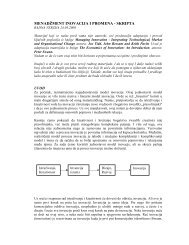
<strong>Mastering</strong> OOAD – Instructor NotesInstructor Notes:Use-Case <strong>Design</strong> in ContextThe focus during Use-Case<strong>Design</strong>, as in Use-Case<strong>Analysis</strong>, is on a specific usecase rather than “the bigpicture,” which is the focus ofthe Architect activities.Use-Case <strong>Design</strong> is where yourefine the use-case realizationsinitially defined in Use-Case<strong>Analysis</strong>. Instead of analysisclasses, you will now describethe use-case realizations interms of design subsystems<strong>and</strong> classes.Use-Case<strong>Design</strong><strong>Design</strong>er[EarlyElaborationIteration]Define a C<strong>and</strong>idateArchitectureRefine theArchitectureDefineComponents[InceptionIteration (Optional)]PerformArchitecturalSynthesisAnalyze Behavior(Optional)<strong>Design</strong> theDatabaseThe difference between Use-Case <strong>Analysis</strong> <strong>and</strong> Use-Case<strong>Design</strong> is scale. <strong>Analysis</strong> classesare quite large (this keeps the<strong>Analysis</strong> Model small). Thismeans that analysis diagramsare quite easy to read <strong>and</strong>underst<strong>and</strong> <strong>and</strong> most of theteam will grasp the wholemodel.Use-Case <strong>Design</strong> focuses onthe externally visible behaviorsof the classes <strong>and</strong> subsystems;the class <strong>and</strong> subsystem designactivities are concerned <strong>with</strong>making sure that the “insides”of the class <strong>and</strong> subsystemscorrectly implement thepublicly visible behaviors.<strong>Mastering</strong> <strong>Object</strong> <strong>Oriented</strong> <strong>Analysis</strong> <strong>and</strong> <strong>Design</strong> <strong>with</strong> <strong>UML</strong>Copyright © 2003 Rational Software, all rights reserved 3As you may recall, the above diagram illustrates the workflow that we areusing in this course. It is a tailored version of the <strong>Analysis</strong> <strong>and</strong> <strong>Design</strong>core workflow of the Rational Unified Process.At this point, you have made an initial attempt at defining thearchitecture. You have defined the major elements of your system (thatis, the subsystems, their interfaces, the design classes, the processes <strong>and</strong>threads) <strong>and</strong> their relationships, <strong>and</strong> you have an underst<strong>and</strong>ing of howthese elements map into the hardware on which the system will run.In Use-Case <strong>Design</strong>, you are going to concentrate on how a use-casehas been implemented <strong>and</strong> make sure that there is consistency frombeginning to end. You will also be verifying that nothing has been missed(that is, you will make sure that what you have done in the previousdesign activities is consistent <strong>with</strong> regards to the use-caseimplementation).Use-Case <strong>Design</strong> is where the design elements (design classes <strong>and</strong>subsystems) meet the architectural mechanisms. The use-case realizationinitially defined in Use-Case <strong>Analysis</strong> is refined to include the designelements, using the patterns of interaction defined for the architecturalmechanisms.You might need to do some Use-Case <strong>Design</strong> before Subsystem <strong>Design</strong>,because after <strong>Analysis</strong> <strong>and</strong> Identify <strong>Design</strong> Elements, you usually onlyhave sketchy notions of responsibilities of classes <strong>and</strong> subsystems. Thereal details need to get worked out in Use-Case <strong>Design</strong>, before you willbe really ready to design the classes <strong>and</strong> subsystems. The detailed designactivities (for example, Subsystem <strong>Design</strong>, Class <strong>Design</strong> <strong>and</strong> Use-Case<strong>Design</strong>) are tightly bound <strong>and</strong> tend to alternate between one another.Module 11 - Use-Case <strong>Design</strong> 11 - 3
<strong>Mastering</strong> OOAD – Instructor NotesInstructor Notes:Use-Case <strong>Design</strong> StepsIn Use-Case <strong>Design</strong>, webasically do two things to theuse-case realizations originallydeveloped during Use-Case<strong>Analysis</strong>:•Replace analysis classes<strong>with</strong> their correspondingdesign elements (forexample, use subsysteminterfaces, whereapplicable).•Incorporate any applicablearchitectural mechanisms,using the sampleinteraction <strong>and</strong> classdiagrams provided by thearchitects.• Describe interaction amongdesign objects• Simplify sequence diagramsusing subsystems• Describe persistence-relatedbehavior• Refine the flow of eventsdescription• Unify classes <strong>and</strong> subsystems<strong>Mastering</strong> <strong>Object</strong> <strong>Oriented</strong> <strong>Analysis</strong> <strong>and</strong> <strong>Design</strong> <strong>with</strong> <strong>UML</strong>Copyright © 2003 Rational Software, all rights reserved 5The above slide shows the major steps of the Use-Case <strong>Design</strong> activity.Use-case realizations evolve from interactions among analysis classes tointeractions among design elements (for example, design classes <strong>and</strong>subsystems).The purpose of Use-Case <strong>Design</strong> is to make sure these are consistent<strong>and</strong> make sense. During Use-Case <strong>Design</strong>, the focus is on the use case,<strong>and</strong> this includes crossing subsystem boundaries. The use-case designerneeds to make sure the use case is implemented completely <strong>and</strong>consistently across the subsystems.Anything done from the use-case perspective is part of Use-Case<strong>Design</strong>.This module will address each of these steps listed on the slide.Module 11 - Use-Case <strong>Design</strong> 11 - 5
<strong>Mastering</strong> OOAD – Instructor NotesInstructor Notes:Use-Case <strong>Design</strong> Steps• Describe interaction among design objects• Simplify sequence diagrams usingsubsystems• Describe persistence-related behavior• Refine the flow of events description• Unify classes <strong>and</strong> subsystems<strong>Mastering</strong> <strong>Object</strong> <strong>Oriented</strong> <strong>Analysis</strong> <strong>and</strong> <strong>Design</strong> <strong>with</strong> <strong>UML</strong>Copyright © 2003 Rational Software, all rights reserved 6In this step, describe the use-case flow of events in terms of the <strong>Design</strong>Model (that is, interactions between design classes <strong>and</strong>/or subsystems).This involves replacing analysis classes <strong>with</strong> the design elements that theywere refined into during Identify <strong>Design</strong> Elements, as well asincorporating any applicable architectural mechanisms.Module 11 - Use-Case <strong>Design</strong> 11 - 6
<strong>Mastering</strong> OOAD – Instructor NotesInstructor Notes:Review: Use-Case RealizationFor details on how to modeluse-case realizations in Rose,see the Instructor Notes for thisslide in the Use-Case <strong>Analysis</strong>module.Use-Case ModelUse Case<strong>Design</strong> ModelUse-Case RealizationSequence DiagramsCollaboration DiagramsUse CaseClass Diagrams<strong>Mastering</strong> <strong>Object</strong> <strong>Oriented</strong> <strong>Analysis</strong> <strong>and</strong> <strong>Design</strong> <strong>with</strong> <strong>UML</strong>Copyright © 2003 Rational Software, all rights reserved 7Before discussing the steps of the Use-Case <strong>Design</strong> activity, it isimportant to review what a use-case realization is, since refining a usecaserealization is the focus of the activity.Use-case realizations were first introduced in the <strong>Analysis</strong> <strong>and</strong> <strong>Design</strong>Overview module. The initial development of use-case realizations wasdiscussed in the Use-Case <strong>Analysis</strong> module. The above diagram isincluded here as a review. For details on the use-case realization, refer tothat module.As stated in that module, a designer is responsible for the integrity of theuse-case realization. He or she must coordinate <strong>with</strong> the designersresponsible for the design elements (that is, classes <strong>and</strong> subsystems) <strong>and</strong>the relationships employed in the use-case realization.Module 11 - Use-Case <strong>Design</strong> 11 - 7
<strong>Mastering</strong> OOAD – Instructor NotesInstructor Notes:Now that we are back in thedesigner activities, this is anopportunity to remind thestudents where we left off inUse-Case <strong>Analysis</strong>. Instead ofworking <strong>with</strong> the <strong>Analysis</strong>classes, we will be working <strong>with</strong>the design elements that wereidentified by the architect in theIdentify <strong>Design</strong> Elementsactivity.Review: From <strong>Analysis</strong> Classes to <strong>Design</strong> Elements<strong>Analysis</strong> Classes<strong>Design</strong> ElementsMany-to-Many Mapping<strong>Mastering</strong> <strong>Object</strong> <strong>Oriented</strong> <strong>Analysis</strong> <strong>and</strong> <strong>Design</strong> <strong>with</strong> <strong>UML</strong>Copyright © 2003 Rational Software, all rights reserved 8Before moving forward in Use-Case <strong>Design</strong>, it is important that yourevisit what happened to the analysis classes that were identified in Use-Case <strong>Analysis</strong>. These analysis classes were mapped to design elementsthat were identified by the architect during the Identify <strong>Design</strong> Elementsactivity. You will be incorporating these design elements into yourmodels in Use-Case <strong>Design</strong>.Identify <strong>Design</strong> Elements is where the analysis classes identified duringUse-Case <strong>Analysis</strong> are refined into design elements (for example, classesor subsystems). <strong>Analysis</strong> classes primarily h<strong>and</strong>le functional requirements<strong>and</strong> model objects from the "problem" domain; design elements h<strong>and</strong>lenonfunctional requirements <strong>and</strong> model objects from the "solution"domain.It is in Identify <strong>Design</strong> Elements that you decide which analysis "classes"are really classes, which are subsystems (that must be furtherdecomposed), <strong>and</strong> which are existing components <strong>and</strong> do not need tobe “designed” at all.Once the design classes <strong>and</strong> subsystems have been created, each mustbe given a name <strong>and</strong> a short description. The responsibilities of theoriginal analysis classes should be transferred to the newly createdsubsystems. In addition, the identified design mechanisms should belinked to design elements.Module 11 - Use-Case <strong>Design</strong> 11 - 8
<strong>Mastering</strong> OOAD – Instructor NotesInstructor Notes:You are essentially taking theuse-case realization diagramsdeveloped in Use-Case<strong>Analysis</strong> <strong>and</strong> redrawing them,using the design elements thatthe analysis classes wererefined into, making sure thatthe responsibility allocation isstill accurate.Collaboration or sequencediagrams may be used tomodel these interactions. RUPrecommends that sequencediagrams be used duringdesign.In the early stages of design,some operations might not bedefined, so you might have toleave this information out <strong>and</strong>give the message a temporaryname; such messages are saidto be "unassigned." Later,when you have found theparticipating objects'operations, you shouldupdate the interactiondiagram by ”mapping" themessages to these operations.Use-Case Realization Refinement• Identify participating objects• Allocate responsibilities among objects• Model messages between objects• Describe processing resulting frommessages• Model associated class relationshipsSequence Diagrams<strong>Mastering</strong> <strong>Object</strong> <strong>Oriented</strong> <strong>Analysis</strong> <strong>and</strong> <strong>Design</strong> <strong>with</strong> <strong>UML</strong>Copyright © 2003 Rational Software, all rights reserved 9Class DiagramsEach use-case realization should be refined to describe the interactionsbetween participating design objects as follows:• Identify each object that participates in the use-case flow of events.These objects can be instances of design classes <strong>and</strong> subsystems, orthey can be instances of actors that the participating objects interact<strong>with</strong>.• Represent each participating object in an interaction diagram.Subsystems can be represented by instances of the subsystem’sinterface(s).• Illustrate the message-sending between objects by creating messages(arrows) between the objects. The name of a message should be thename of the operation invoked by it. For messages going to designclasses, the operation is a class operation. For messages going tosubsystems, the operation is an interface operation.• Describe what an object does when it receives a message. This isdone by attaching a script or note to the corresponding message.When the person responsible for an object's class assigns <strong>and</strong> definesits operations, these notes or scripts will provide a basis for thatwork.For each use-case realization, illustrate the class relationships thatsupport the collaborations modeled in the interaction diagrams bycreating one or more class diagrams.Module 11 - Use-Case <strong>Design</strong> 11 - 9
<strong>Mastering</strong> OOAD – Instructor NotesInstructor Notes:Note: On the presented slide,the items that were added <strong>and</strong>utilized as part ofincorporating the subsysteminterface are shown in yellow,but this does not show up inthe black-<strong>and</strong>-white manuals.Use-Case Realization Refinement Steps• Identify each object that participates in theflow of the use case• Represent each participating object in asequence diagram• Incrementally incorporate applicablearchitectural mechanisms<strong>Mastering</strong> <strong>Object</strong> <strong>Oriented</strong> <strong>Analysis</strong> <strong>and</strong> <strong>Design</strong> <strong>with</strong> <strong>UML</strong>Copyright © 2003 Rational Software, all rights reserved 10Look at the interaction diagrams.For each class that has been refined into a subsystem, replace the class<strong>with</strong> the associated subsystem interface. Any interactions that describehow the subsystem should implement the service should be deferreduntil subsystem design.Incrementally incorporate any applicable architectural mechanisms,using the patterns of behavior defined for them during the architecturalactivities.This may include the introduction of new design elements <strong>and</strong>messages.Any updates need to be reflected in both the static <strong>and</strong> dynamic parts ofthe use-case realization (that is, the interaction diagrams <strong>and</strong> the VOPCclass diagram).Module 11 - Use-Case <strong>Design</strong> 11 - 10
<strong>Mastering</strong> OOAD – Instructor NotesInstructor Notes:There are two ways that thestudent can represent asubsystem on a sequencediagram; <strong>with</strong> an interface ora subsystem proxy. Use theproxy only if you know whatsubsystem is going to be beused to realize the behavior.The first message on the slideis invalid because it comesfrom an interface. The secondmessage is valid because itcomes from a proxy class.Representing Subsystems on a Sequence Diagram• Interfaces• Represent any model element that realizes the interface• No message should be drawn from the interface• Proxy class• Represents a specific subsystem• Messages can be drawn from the proxy<strong>Object</strong> A Interface <strong>Object</strong> B1: Message 1X2: Message 2<strong>Object</strong> A Proxy <strong>Object</strong> B1: Message 12: Message 2Invalid messageValid message<strong>Mastering</strong> <strong>Object</strong> <strong>Oriented</strong> <strong>Analysis</strong> <strong>and</strong> <strong>Design</strong> <strong>with</strong> <strong>UML</strong>Copyright © 2003 Rational Software, all rights reserved 11You have two choices for representing the subsystems:• You can use the interfaces realized by the subsystem. This is thebetter choice in cases where any model element that realizes thesame interface can be used in place of the interface. If you chooseto show interfaces on the sequence diagram, be aware that you willwant to ensure that no messages are sent from the interface to otherobjects. The reason for this is that interfaces completely encapsulatethe internal realization of their operations. Therefore, you cannot becertain that all model elements that realize the interface will in factactually be designed the same way. So on sequence diagrams, nomessages should be shown being sent from interfaces.• You can use a proxy class (which is discussed in the Subsystem<strong>Design</strong> Module) to represent the subsystem on sequence diagrams.This proxy class is contained <strong>with</strong>in the subsystem <strong>and</strong> is used torepresent the subsystem in diagrams that do not support the directuse of packages <strong>and</strong> subsystems as behavioral elements. The proxyclass should be used in cases where a specific subsystem responds toa message. Messages can be sent from the subsystem proxy to otherobjects.For this class, you will use interfaces to represent subsystems in thedesign.Module 11 - Use-Case <strong>Design</strong> 11 - 11
<strong>Mastering</strong> OOAD – Instructor NotesInstructor Notes:Example: Incorporating Subsystem InterfacesEmphasize the rationale forchoosing these subsystems —external system access.<strong>Analysis</strong> ClassesBillingSystem<strong>Design</strong> ElementsBilling System//submit bill()IBillingSystemsubmitBill(forTuition : Double, forStudent : Student)CourseCatalogSystemCourse CatalogSystem//get course offerings()ICourseCatalogSystemgetCourseOfferings(forSemester : Semester, forStudent : Student) : CourseOfferingListinitialize()<strong>Analysis</strong> classes are mapped directly to design classes.<strong>Mastering</strong> <strong>Object</strong> <strong>Oriented</strong> <strong>Analysis</strong> <strong>and</strong> <strong>Design</strong> <strong>with</strong> <strong>UML</strong>Copyright © 2003 Rational Software, all rights reserved 12In Identify <strong>Design</strong> Elements, it was determined by the architects of theCourse Registration System that the interactions to support externalsystem access were going to be more complex than could beimplemented in a single class. Thus, subsystems were identified toencapsulate the access to these external systems. The above diagramincludes these subsystems, as well as their interfaces.The BillingSystem subsystem provides an interface to the external BillingSystem. It is used to submit a bill when registration ends <strong>and</strong> studentshave been registered in courses.The CourseCatalogSystem subsystem encapsulates all the work that goeson in communicating to the legacy Course Catalog System. The systemprovides access to the unabridged catalog of all courses <strong>and</strong> courseofferings offered by the university, including those from previoussemesters.All other analysis classes map directly to design classes in the <strong>Design</strong>Model.Module 11 - Use-Case <strong>Design</strong> 11 - 12
<strong>Mastering</strong> OOAD – Instructor NotesInstructor Notes:Example: Incorporating Subsystem Interfaces (Before)<strong>Analysis</strong> class to be replaced <strong>with</strong> an interface: StudentStudent wishesto create a newschedule: RegisterForCoursesForm : RegistrationController : CourseCatalogSystem : Schedule : Student1. // create schedule( )1.1. // get course offerings( )1.2. // display course offerings( )A list of the availablecourse offerings for thissemester are displayedA blank scheduleis displayed for thestudents to selectofferings1.3. // display blank schedule( )2. // select 4 primary <strong>and</strong> 2 alternate offerings( )1.1.1. // get course offerings(forSemester)2.1. // create schedule <strong>with</strong> offerings( )2.1.1. // create <strong>with</strong> offerings( )2.1.2. // add schedule(Schedule)At this point, the Submit Schedule subflow is executed<strong>Mastering</strong> <strong>Object</strong> <strong>Oriented</strong> <strong>Analysis</strong> <strong>and</strong> <strong>Design</strong> <strong>with</strong> <strong>UML</strong>Copyright © 2003 Rational Software, all rights reserved 13The above slide shows part of the Register for Courses use-caserealization developed during Use-Case <strong>Analysis</strong>.You know from Identify <strong>Design</strong> Elements that a CourseCatalogSystemsubsystem has been defined to encapsulate access to the external legacyCourseCatalogSystem. Thus, you need to refine this interaction diagram<strong>and</strong> replace the original CourseCatalogSystem boundary class <strong>with</strong> theassociated subsystem interface, ICourseCatalogSystem.Module 11 - Use-Case <strong>Design</strong> 11 - 13
<strong>Mastering</strong> OOAD – Instructor NotesInstructor Notes:Example: Incorporating Subsystem Interfaces (After)Replaced <strong>with</strong> subsystem interface: StudentStudent wishesto create a newschedule: RegisterForCoursesForm : RegistrationController : ICourseCatalogSystem : Schedule : Student1. // create schedule( )1.1. // get course offerings( )1.2. // display course offerings( )A list of the availablecourse offerings for thissemester are displayedA blank scheduleis displayed for theStudent to selectofferings1.3. // display blank schedule( )2. // select 4 primary <strong>and</strong> 2 alternate offerings( )1.1.1. getCourseOfferings(Semester)2.1. // create schedule <strong>with</strong> offerings( )2.1.1. // create <strong>with</strong> offerings( )2.1.2. // add schedule(Schedule)At this point, the Submit Schedule subflow is executed<strong>Mastering</strong> <strong>Object</strong> <strong>Oriented</strong> <strong>Analysis</strong> <strong>and</strong> <strong>Design</strong> <strong>with</strong> <strong>UML</strong>Copyright © 2003 Rational Software, all rights reserved 14The above is a fragment of the sequence diagram from the Register forCourses use-case realization. It demonstrates how interactions aremodeled between design elements, where one of the elements is asubsystem.You know from Identify <strong>Design</strong> Elements that a CourseCatalogSystemsubsystem was defined to encapsulate access to the external legacyCourseCatalogSystem. Thus, the original use-case realization (shown onthe previous slide) was refined, <strong>and</strong> the original CourseCatalogSystemboundary class was replaced <strong>with</strong> the associated subsystem interface,ICourseCatalogSystem.In this module, you will not flesh out the internals of theCourseCatalogSystem subsystem. That is the purpose of Subsystem<strong>Design</strong>. The above diagram will become the subsystem context diagramin Subsystem <strong>Design</strong>. In Subsystem <strong>Design</strong>, you will concentrate on theinternals of the subsystem.Module 11 - Use-Case <strong>Design</strong> 11 - 14
<strong>Mastering</strong> OOAD – Instructor NotesInstructor Notes:On the presented slide, theitems that were added <strong>and</strong>utilized as part ofincorporating the subsysteminterface are shown in yellow,but this does not show up inthe black-<strong>and</strong>-white manuals.Example: Incorporating Subsystem Interfaces (VOPC)RegisterForCoursesForm(from Registration)// submit schedule()// display course offerings()// display schedule()// save schedule()// create schedule()// select 4 primary <strong>and</strong> 2 alternate offerings()// display blank schedule()Subsystem interfaceICourseCatalogSystem(from External System Interfaces)RegistrationController(from Registration)0..* 1getCourseOfferings()initialize()// submit schedule()1 1// save schedule()// create schedule <strong>with</strong> offerings() 0..1Schedule// getCourseOfferings()currentSchedule (from University Artifacts)semester0..10..1registrant// submit()0..1// save()0..*// any conflicts?()Student.// new()0..*0..*(from University Artifacts)-name-address1alternateCourses- studentID : int0..2primaryCourses// addSchedule()0..4 CourseOffering// getSchedule()(from University Artifacts)// hasPrerequisites()number// passed()startTimeendTimedays// addStudent()// removeStudent()// new()// setData()<strong>Mastering</strong> <strong>Object</strong> <strong>Oriented</strong> <strong>Analysis</strong> <strong>and</strong> <strong>Design</strong> <strong>with</strong> <strong>UML</strong>Copyright © 2003 Rational Software, all rights reserved 15The above example is the VOPC after incorporating the design elements.The original CourseCatalogSystem boundary class has been replaced<strong>with</strong> the associated subsystem interface, ICourseCatalogSystem.Module 11 - Use-Case <strong>Design</strong> 11 - 15
<strong>Mastering</strong> OOAD – Instructor NotesInstructor Notes:Emphasize to the students thatyou will not be covering theincorporation of the securitymechanism; however, thedetails can be found in theAdditional InformationAppendix.If you choose to present thesecurity mechanism, the slidesfound in the AdditionalInformation Appendix,Security Mechanism section,second part, should beinserted after this slide.Note: On the presented slide,the italicized text is alsoyellow, but this does not showup in the black-<strong>and</strong>-whitemanuals.This module will discussincorporating the distribution<strong>and</strong> persistence mechanisms.Incorporating Architectural Mechanisms: Security• <strong>Analysis</strong>-Class-to-Architectural-MechanismMap from Use-Case <strong>Analysis</strong><strong>Analysis</strong> ClassStudentScheduleCourseOfferingCourseRegistrationControllerDetails are in the appendix.<strong>Mastering</strong> <strong>Object</strong> <strong>Oriented</strong> <strong>Analysis</strong> <strong>and</strong> <strong>Design</strong> <strong>with</strong> <strong>UML</strong>Copyright © 2003 Rational Software, all rights reserved 16<strong>Analysis</strong> Mechanism(s)Persistency, SecurityPersistency, SecurityPersistency, Legacy InterfacePersistency, Legacy InterfaceDistributionDuring Use-Case <strong>Analysis</strong>, applicable mechanisms for each identifiedanalysis class were documented. This information, along <strong>with</strong> theinformation on what analysis classes became what design elements,allows the applicable mechanisms for a design element to be identified.Since we have been concentrating on course registration, the abovetable contains only the classes for the Register for Courses use-caserealization that have analysis mechanisms assigned to them.The details of incorporating the security mechanism are provided in theAdditional Information Appendix in the Security Mechanism section.Module 11 - Use-Case <strong>Design</strong> 11 - 16
<strong>Mastering</strong> OOAD – Instructor NotesInstructor Notes:The distribution mechanismwas last discussed in theDescribe Distributionmodule.Incorporating Architectural Mechanisms: Distribution• <strong>Analysis</strong>-Class-to-Architectural-MechanismMap from Use-Case <strong>Analysis</strong><strong>Analysis</strong> Class<strong>Analysis</strong> Mechanism(s)StudentScheduleCourseOfferingCourseRegistrationControllerPersistency, SecurityPersistency, SecurityPersistency, Legacy InterfacePersistency, Legacy InterfaceDistribution<strong>Mastering</strong> <strong>Object</strong> <strong>Oriented</strong> <strong>Analysis</strong> <strong>and</strong> <strong>Design</strong> <strong>with</strong> <strong>UML</strong>Copyright © 2003 Rational Software, all rights reserved 17We started the discussion of the distribution mechanism in the DescribeDistribution module. Now we will see how to incorporate thismechanism into the use-case realizations.Module 11 - Use-Case <strong>Design</strong> 11 - 17
<strong>Mastering</strong> OOAD – Instructor NotesInstructor Notes:This slide summarizes thesteps that must be taken toincorporate the distributionmechanism.Note: On the presented slide,the italicized text is also blue,but this does not show up inthe black-<strong>and</strong>-white manuals.The checked steps havealready been done, so now wecan see what is left to beaccomplished.Review: Incorporating RMI: Steps• Provide access to RMI support classes (e.g.,Remote <strong>and</strong> Serializable interfaces, NamingService)√ • Use java.rmi <strong>and</strong> java.io package in Middleware layer• For each class to be distributed:√ • Controllers to be distributed are in Application layer√ • Dependency from Application layer to Middleware layeris needed to access java packages• Define interface for class that realizes Remote• Have class inherit from UnicastRemote<strong>Object</strong>√ - Done<strong>Mastering</strong> <strong>Object</strong> <strong>Oriented</strong> <strong>Analysis</strong> <strong>and</strong> <strong>Design</strong> <strong>with</strong> <strong>UML</strong>Copyright © 2003 Rational Software, all rights reserved 18The next few slides contain a summary of the steps that can be used toimplement the RMI distribution mechanism described in this module.The italicized text describes the architectural decisions made <strong>with</strong>regards to RMI for our Course Registration example.These steps were first discussed in the Describe Distribution module.They are repeated here for convenience. The check marks indicate whatsteps have been completed.In Use-Case <strong>Design</strong>, you will continue to incorporate this mechanism.You will define the distributed class interfaces, <strong>and</strong> the supportinggeneralization <strong>and</strong> realization relationships. As pointed out in theDescribe Distribution module, for any class that is to be distributed, aninterface must be defined that realizes the Java Remote interface. Thedistributed class will need to realize that interface, as well as inherit fromUnicastRemote<strong>Object</strong>.As previously decided, for the Course Registration System, the controlclasses will be distributed. (The classes to be distributed were tagged <strong>with</strong>the analysis mechanism, distribution.) The interface classes that will bedefined for the distributed control classes should be placed in the samepackage as the associated distributed control classes.The remaining steps are discussed on the next two slides.Module 11 - Use-Case <strong>Design</strong> 11 - 18
<strong>Mastering</strong> OOAD – Instructor NotesInstructor Notes:This slide summarizes thesteps that must be taken toincorporate the distributionmechanism.Note: On the presented slide,the italicized text is also blue,but this does not show up inthe black-<strong>and</strong>-white manuals.Review: Incorporating RMI: Steps (cont.)• Have classes for data passed to distributedobjects realize the Serializable interface√ • Core data types are in Business Services layer√ • Dependency from Business Services layer toMiddleware layer is needed to get access tojava.rmi• Add the realization relationships• Run pre-processor – out of scope√ - Done<strong>Mastering</strong> <strong>Object</strong> <strong>Oriented</strong> <strong>Analysis</strong> <strong>and</strong> <strong>Design</strong> <strong>with</strong> <strong>UML</strong>Copyright © 2003 Rational Software, all rights reserved 19• Any class whose instances will be passed between the client <strong>and</strong> theserver needs to realize the Serializable interface.For the Course Registration System, most of the data passed is of oneof the core data types. The core data types were allocated to theBusiness Services layer of the architecture (specifically, the UniversityArtifacts package) in Identify <strong>Design</strong> Elements. Thus, a dependencyexists from the Business Services layer to the Middleware layer so thecore data classes can access to Remote interface. Now we willdefine the realization relationships from the classes to be passed <strong>and</strong>the Serializable interface.• The developer must run the compiled distributed class through thermic compiler provide by Sun to generate the stubs <strong>and</strong> skeletons forall classes that realize the Remote interface. These classes h<strong>and</strong>lethe communication that must occur to support distribution (see theprevious slide). Once a class is run through RMIC, you can access itas if it were a local class; the client does not know the difference.This is really implementation, which is out of the scope of thiscourse.The remaining steps are discussed on the next slide.Module 11 - Use-Case <strong>Design</strong> 11 - 19
<strong>Mastering</strong> OOAD – Instructor NotesInstructor Notes:This slide summarizes thesteps that must be taken toincorporate the distributionmechanism.Note: On the presented slide,the italicized text is also blue,but this does not show up inthe black-<strong>and</strong>-white manuals.Review: Incorporating RMI: Steps (cont.)• Have distributed class clients look up theremote objects using the Naming service√ • Most Distributed Class Clients are forms√ • Forms are in Application layer√ • Dependency from Application layer toMiddleware layer is needed to get access tojava.rmi• Add relationship from Distributed Class Clientsto Naming Service• Create/update interaction diagrams <strong>with</strong>distribution processing (optional)√ -Done<strong>Mastering</strong> <strong>Object</strong> <strong>Oriented</strong> <strong>Analysis</strong> <strong>and</strong> <strong>Design</strong> <strong>with</strong> <strong>UML</strong>Copyright © 2003 Rational Software, all rights reserved 20Clients of distributed classes will need to lookup the location of theremote object using the Naming service. The look up returns a referenceto the distributed class interface.Now we will define the dependency relationships from the distributedclass clients <strong>and</strong> the Naming Service. You will also develop interactiondiagrams that model the distribution functionality.Module 11 - Use-Case <strong>Design</strong> 11 - 20
<strong>Mastering</strong> OOAD – Instructor NotesInstructor Notes:Example: Incorporating RMIOn the presented slide, thechanges to supportdistribution are shown <strong>with</strong>red arrows (distributed classclient, distributed class, <strong>and</strong>passed class).Naming(from rmi)+ lookup()DistributedClass ClientRegisterForCoursesForm(from Registration)11IRegistrationController(from Registration)+ getCurrentSchedule(forStudent : Student, forSemester : Semester) : Schedule+ deleteCurrentSchedule()+ submitSchedule()+ saveSchedule()+ getCourseOfferings() : CourseOfferingListPassed ClassRemote(from rmi)CourseOfferingList(from University Artifacts)0..1Student(from University Artifacts)registrant1DistributedClassRegistrationController(from Registration)0..1currentSchedule0..10..1Schedule(from University Artifacts)0..nSerializable(from io)UnicastRemote<strong>Object</strong>(from server)<strong>Mastering</strong> <strong>Object</strong> <strong>Oriented</strong> <strong>Analysis</strong> <strong>and</strong> <strong>Design</strong> <strong>with</strong> <strong>UML</strong>Copyright © 2003 Rational Software, all rights reserved 21The above diagram provides a static view of the classes needed toincorporate the RMI distribution mechanism into the Course RegistrationSystem design.The RegistrationController class is distributed, so an interface wasdefined, IRegistrationController, that realizes the Remote interface. Thedistributed class, RegistrationController realizes this new interface, <strong>and</strong>inherits from the UnicastRemote<strong>Object</strong>.Instances of the Student, Schedule, <strong>and</strong> CourseOfferingList classes arepassed to <strong>and</strong> from the distributed class (note the operation signaturesfor the IRegistrationController interface), so they will realize theSerializable interface.The RegisterForCoursesForm needs to look up the location of theRegistrationController using the Naming service, so a dependency wasadded from the RegisterForCoursesForm to Naming.The remaining steps are discussed on the next two slides.Module 11 - Use-Case <strong>Design</strong> 11 - 21
<strong>Mastering</strong> OOAD – Instructor NotesInstructor Notes:Example: Incorporating RMI (cont.)On the presented slide, thechanges to supportdistribution are shown inyellow, but this does not showup in the black-<strong>and</strong>-whitemanuals.Business ServicesUniversity Artifacts(from Business Services)ApplicationRegistrationPackage(from Application)ApplicationMiddlewareBusinessServicesjava.rmiJava.ioSerializable(from java.io)Naming(from java.rmi)remote(from java.rmi)ServerUnicastRemote<strong>Object</strong>(from Server)Middleware<strong>Mastering</strong> <strong>Object</strong> <strong>Oriented</strong> <strong>Analysis</strong> <strong>and</strong> <strong>Design</strong> <strong>with</strong> <strong>UML</strong>Copyright © 2003 Rational Software, all rights reserved 22The above diagram describes the package dependencies needed tosupport the distribution pattern described in this module (<strong>and</strong> the classrelationships shown on the previous slide). This diagram is very similar tothe one included in the Describe Distribution module, but the genericSample Application package has been replaced <strong>with</strong> the Registrationpackage. The Registration package contains the RegistrationControllerclass that needs to be distributed; the created IRegistrationControllerinterface; <strong>and</strong> the distributed class client, the RegisterForCoursesFormclass. As discussed in the Describe Distribution module, the followingpackage dependencies were added to support distribution:• The java.rmi package contains the classes that implement the RMIdistribution mechanism. This package is commercially available <strong>with</strong>most st<strong>and</strong>ard Java IDEs.• Dependency from the Application packages to java.rmi providesaccess to the Remote interface for distributed controller interfaces,<strong>and</strong> to the Naming service for the distributed controller clients.• Dependency from the Application packages to the Java Serverpackage provides access to the UnicastRemote<strong>Object</strong> class fordistributed controllers.• Dependency from the University Artifacts package to java.ioprovides access to the Serializable interface for classes, whoseinstances must be passed for distributed objects.The layer dependencies that support the package dependencies areshown on the right side of diagram.Note: In the above diagram, only a subset of the packages are shown.The remaining packages have been omitted for clarity. The remainingsteps are discussed on the next slide.Module 11 - Use-Case <strong>Design</strong> 11 - 22
<strong>Mastering</strong> OOAD – Instructor NotesInstructor Notes:This interaction diagramfragment is included forexample purposes only. Itdoes not exist in the exampleCourse Registration model,although the model does usethis method documentingdistribution.Note: On the presented slide,the changes to supportdistribution are shown inwhite, but this does not showup in the black-<strong>and</strong>-whitemanuals.Example: Incorporating RMI (cont.)Added to support distributionRegisterForCoursesForm : Naming. :IRegistrationController1: lookup(string)2: doSomethingLookup remoteobject by specifyingit's URLAll calls to the distributed class interface areforwarded to the remote instance.<strong>Mastering</strong> <strong>Object</strong> <strong>Oriented</strong> <strong>Analysis</strong> <strong>and</strong> <strong>Design</strong> <strong>with</strong> <strong>UML</strong>Copyright © 2003 Rational Software, all rights reserved 23The above diagram provides an example of what you would include inan interaction diagram to model the distribution functionality.Notice the addition of a call to the Naming utility to locate thedistributed class instance as well as the replacement of the originalRegistrationController control class <strong>with</strong> the IRegistrationControllerinterface. (Naming returns a reference to an IRegistrationController.) Theremainder of the interaction diagram remains the same as before thedistribution mechanism was incorporated.Module 11 - Use-Case <strong>Design</strong> 11 - 23
<strong>Mastering</strong> OOAD – Instructor NotesInstructor Notes:Use-Case <strong>Design</strong> Steps• Describe interaction among design objects• Simplify sequence diagrams usingsubsystems• Describe persistence-related behavior• Refine the flow of events description• Unify classes <strong>and</strong> subsystems<strong>Mastering</strong> <strong>Object</strong> <strong>Oriented</strong> <strong>Analysis</strong> <strong>and</strong> <strong>Design</strong> <strong>with</strong> <strong>UML</strong>Copyright © 2003 Rational Software, all rights reserved 24When a use case is realized, the flow of events is usually described interms of the executing objects, that is, as interactions between designobjects. To simplify diagrams <strong>and</strong> to identify reusable behavior, theremight be a need to encapsulate a subflow of events <strong>with</strong>in a subsystem.When this is done, large subsections of the interaction diagram arereplaced <strong>with</strong> a single message to the subsystem. Within the subsystem, aseparate interaction diagram might illustrate the internal interactions<strong>with</strong>in the subsystem that provide the required behavior. Thesesubsystem interaction diagrams are developed during Subsystem <strong>Design</strong>.At first glance, this step may appear similar to the previous one, DescribeInteractions among <strong>Design</strong> <strong>Object</strong>s. However, they differ in perspective.In the case of Describe Interactions among <strong>Design</strong> <strong>Object</strong>s, the commonsubflows are identified outside-in. (Common collaborations have alreadybeen encapsulated <strong>with</strong>in the subsystems identified in Identify <strong>Design</strong>Elements.) In the case of Simplify Interaction Diagrams UsingSubsystems, the common subflows are discovered inside-out — aftermodeling the flows of events using design elements, you recognizecommon subflows. This step is optional if common subflows are notdiscovered.Module 11 - Use-Case <strong>Design</strong> 11 - 24
<strong>Mastering</strong> OOAD – Instructor NotesInstructor Notes:Encapsulating Subsystem Interactions• Interactions can be described at severallevels• Subsystem interactions can be described intheir own interaction diagramsRaises the level of abstraction<strong>Mastering</strong> <strong>Object</strong> <strong>Oriented</strong> <strong>Analysis</strong> <strong>and</strong> <strong>Design</strong> <strong>with</strong> <strong>UML</strong>Copyright © 2003 Rational Software, all rights reserved 25A use-case realization can be described, if necessary, at several levels inthe subsystem hierarchy.In the above example, the lifelines in the middle diagram representsubsystems; the interactions in the circles represent the internalinteraction of subsystem members in response to the message.This approach raises the level of abstraction of the use-case realizationflows of events.The advantages of this approach are described on the next three slides.Module 11 - Use-Case <strong>Design</strong> 11 - 25
<strong>Mastering</strong> OOAD – Instructor NotesInstructor Notes:This slide lists those instanceswhen subsequences ofmessages (a.k.a. subflows)<strong>with</strong>in interaction diagramsshould be encapsulated <strong>with</strong>ina subsystem.Sometimes you see repeatedpatterns of interaction in theseearly use-case realizations thatgive birth to new subsystems<strong>and</strong> some revisions in the usecaserealizations. It isimportant for the architect tolook <strong>with</strong>in <strong>and</strong> acrosssubsystems for commonbehavior (commoncollaboration) <strong>with</strong>in thesubsystems, pulling it outwhere possible. This is areuse scavenging activity thatfalls under the Identify <strong>Design</strong>Elements umbrella.The subflow encapsulated<strong>with</strong>in the subsystem becomesa behavior of that subsystem<strong>and</strong> should be defined in aninterface that the subsystemrealizes. Existingdependencies need to beadjusted to support the newor refined interface.Adjustment or refinement ofsubsystem interfaces <strong>and</strong>dependencies is an Identify<strong>Design</strong> Elements activity thatshould be performed by thearchitect. The modeling ofthe collaborations <strong>with</strong>in asubsystem is a Subsystem<strong>Design</strong> activity that should beperformed by the subsystem<strong>Design</strong>er.When to Encapsulate Subflows in a SubsystemEncapsulate a Subflow when it:• Occurs in multiple use-case realizations• Has reuse potential• Is complex <strong>and</strong> easily encapsulated• Is responsibility of one person or team• Produces a well-defined result• Is encapsulated <strong>with</strong>in a single ImplementationModel component<strong>Mastering</strong> <strong>Object</strong> <strong>Oriented</strong> <strong>Analysis</strong> <strong>and</strong> <strong>Design</strong> <strong>with</strong> <strong>UML</strong>Copyright © 2003 Rational Software, all rights reserved 26Encapsulate a subflow <strong>with</strong>in a subsystem when it:• Occurs repeatedly in different use-case realizations: Similar messagesare sent to similar objects, providing the same end result. The word“similar” is used because some design work may be needed to makethe behavior reusable.• Occurs in only one use-case realization but it is expected to beperformed repeatedly in future iterations, or in similar systems in thefuture. The behavior may make a good reusable component.• Occurs in only one use-case realization but is complex <strong>and</strong> easilyencapsulated, needs to be the responsibility of one person or ateam, <strong>and</strong> provides a well-defined result. In these kinds of situations,the complex behavior usually requires special technical knowledge,or special domain knowledge. As a result, it is wellsuited toencapsulation <strong>with</strong>in a subsystem.• Is encapsulated <strong>with</strong>in a component in the Implementation Model.In this case, a subsystem is the appropriate representation for thecomponent <strong>with</strong>in the <strong>Design</strong> Model.Make sure that what you are abstracting is worth abstracting.Module 11 - Use-Case <strong>Design</strong> 11 - 26
<strong>Mastering</strong> OOAD – Instructor NotesInstructor Notes:Guidelines: Encapsulating Subsystem Interactions• Subsystems should be represented by theirinterfaces on interaction diagrams• Messages to subsystems are modeled asmessages to the subsystem interface• Messages to subsystems correspond tooperations of the subsystem interface• Interactions <strong>with</strong>in subsystems are modeled inSubsystem <strong>Design</strong>MySubsystem:InterfaceAInterfaceAop1()op1()<strong>Mastering</strong> <strong>Object</strong> <strong>Oriented</strong> <strong>Analysis</strong> <strong>and</strong> <strong>Design</strong> <strong>with</strong> <strong>UML</strong>Copyright © 2003 Rational Software, all rights reserved 27To achieve true substitutability of subsystems that realize the sameinterface, only their interfaces can be visible in the interaction diagrams;otherwise all diagrams will need to be changed whenever a subsystem issubstituted for another.On an interaction diagram, sending a message to an interface lifelinemeans that any subsystem that realizes the interface can be substitutedfor the interface in the diagram.In many cases, the interface lifeline does not have messages going outfrom it, since different subsystems realizing the interface may senddifferent messages. However, if you want to describe what messagesshould be sent (or are allowed to be sent) from any subsystem realizingthe interface, such messages can originate from the interface lifeline.With this approach, when describing the interactions, the focus remainson the services, not on how the services are implemented <strong>with</strong>in thedesign elements. This is known as “<strong>Design</strong> by Contract” <strong>and</strong> is one of thecore tenets of robust software development using abstraction <strong>and</strong>encapsulation mechanisms.Describing how the services are implemented is the focus of Subsystem<strong>Design</strong> for the design subsystems <strong>and</strong> Class <strong>Design</strong> for the design classes.Module 11 - Use-Case <strong>Design</strong> 11 - 27
<strong>Mastering</strong> OOAD – Instructor NotesInstructor Notes:Parallel subsystemdevelopment is discussed inmore detail on the next slide.Advantages of Encapsulating Subsystem InteractionsUse-case realizations:• Are less cluttered• Can be created before the internal designs ofsubsystems are created (parallel development)• Are more generic <strong>and</strong> easier to change(Subsystems can be substituted.)<strong>Mastering</strong> <strong>Object</strong> <strong>Oriented</strong> <strong>Analysis</strong> <strong>and</strong> <strong>Design</strong> <strong>with</strong> <strong>UML</strong>Copyright © 2003 Rational Software, all rights reserved 28The advantages of encapsulating subsystem interactions over modelingthe entire system at once are:• Use-case realizations become less cluttered, especially if the internaldesign of some subsystems is complex.• Use-case realizations can be created before the internal designs ofsubsystems are created. This can be used to make sure that use-casefunctionality has not been “lost” between the allocation of use-caseresponsibility in Use-Case <strong>Analysis</strong> <strong>and</strong> the identification of designelements (subsystems <strong>and</strong> design classes) in Identify <strong>Design</strong>Elements, <strong>and</strong> before Subsystem <strong>Design</strong> is performed.• Use-case realizations become more generic <strong>and</strong> easier to change,especially if a subsystem needs to be substituted for anothersubsystem.Encapsulating subsystem interactions raises the level of abstraction of theuse-case realization flows of events.Module 11 - Use-Case <strong>Design</strong> 11 - 28
<strong>Mastering</strong> OOAD – Instructor NotesInstructor Notes:This is critical information. Itreally describes parallelsoftware development, whichis enabled via theestablishment of a welldefined<strong>and</strong> stablearchitecture.Note: This discussion holdstrue for packages if yousubstitute “public classes” for“interfaces.” That being said,anytime you find yourselfwanting to define packages<strong>with</strong> some public classes <strong>and</strong>mostly implementation classes,you may want to considerusing a subsystem instead —to employ a more robustmodeling technique (nodependencies on anythinginside subsystem).Parallel Subsystem Development• Concentrate on requirements that affectsubsystem interfaces• Outline required interfaces• Model messages that cross subsystemboundaries• Draw interaction diagrams in terms ofsubsystem interfaces for each use case• Refine the interfaces needed to providemessages• Develop each subsystem in parallelUse subsystem interfaces as synchronization points<strong>Mastering</strong> <strong>Object</strong> <strong>Oriented</strong> <strong>Analysis</strong> <strong>and</strong> <strong>Design</strong> <strong>with</strong> <strong>UML</strong>Copyright © 2003 Rational Software, all rights reserved 29In some cases, it is appropriate to develop a subsystem more or lessindependently <strong>and</strong> in parallel <strong>with</strong> the development of other subsystems.To achieve this, we must first find subsystem dependencies by identifyingthe interfaces between them.This work can be done as follows:1.Concentrate on the requirements that affect the interfaces betweenthe subsystems.2.Make outlines of the required interfaces, showing the messages thatare going to pass over the subsystem borders.3.Draw interaction diagrams in terms of subsystem interfaces for eachuse case.4.Refine the interfaces needed to provide messages.5.Develop each subsystem in parallel using the interfaces assynchronization instruments between development teams.You can also choose whether to arrange the interaction diagrams interms of subsystems or in terms of their interfaces only. In some projects,it might even be necessary to implement the classes providing theinterfaces before you continue <strong>with</strong> the rest of the modeling.The detailed design of the subsystem “internals” is done duringSubsystem <strong>Design</strong>. The interfaces are what ensure compatibilitybetween the Use-Case <strong>Design</strong> <strong>and</strong> the Subsystem <strong>Design</strong>.Module 11 - Use-Case <strong>Design</strong> 11 - 29
<strong>Mastering</strong> OOAD – Instructor NotesInstructor Notes:Use-Case <strong>Design</strong> Steps• Describe interaction among design objects• Simplify sequence diagrams usingsubsystems• Describe persistence-related behavior• Refine the flow of events description• Unify classes <strong>and</strong> subsystems<strong>Mastering</strong> <strong>Object</strong> <strong>Oriented</strong> <strong>Analysis</strong> <strong>and</strong> <strong>Design</strong> <strong>with</strong> <strong>UML</strong>Copyright © 2003 Rational Software, all rights reserved 30You will now take a closer look at the incorporation of the persistencymechanism.Module 11 - Use-Case <strong>Design</strong> 11 - 30
<strong>Mastering</strong> OOAD – Instructor NotesInstructor Notes:Remind the students thatwe’re not trying to teach themhow to design the persistencymechanism, but that we wantthem to merely be able toproduce designs that caneffectively use the persistencymechanism defined by thearchitect in Identify <strong>Design</strong>Mechanisms.In some cases, there may notbe a visual model (or the visualmodel would add little value,since most of it is h<strong>and</strong>led byimplementation mechanisms).In these cases, annotation ofexisting interaction diagrams<strong>with</strong> notes <strong>and</strong> scripts can beused to describe where themechanisms come into play.In this activity, the abstractpatterns of persistent behavior(examples of which wereprovided in Identify <strong>Design</strong>Mechanisms) get realized interms of the actual designclasses in the system. Theexamples on the slidesdemonstrate howimplementation mechanisms(specifically, the persistencemechanisms) drive designactivities <strong>and</strong> why it’s soimportant to establish suchinfrastructure early in thesoftware lifecycle.Use-Case <strong>Design</strong> Steps: Describe Persistence-Related Behavior• Describe Persistence-Related Behavior• Modeling Transactions• Writing Persistent <strong>Object</strong>s• Reading Persistent <strong>Object</strong>s• Deleting Persistent <strong>Object</strong>s<strong>Mastering</strong> <strong>Object</strong> <strong>Oriented</strong> <strong>Analysis</strong> <strong>and</strong> <strong>Design</strong> <strong>with</strong> <strong>UML</strong>Copyright © 2003 Rational Software, all rights reserved 31In practice, there may be times when the application needs to controlvarious aspects of persistence. These include:• When determining how transactions are managed.• When persistent objects are written — either the initial time whenthe object is written to the persistent object store or the subsequenttimes when the object is updated.• When persistent objects are read. Retrieval of objects from thepersistent object store is necessary before the application can sendmessages to that object. You need to send a message to an objectthat knows how to query the database, retrieve the correct objects,<strong>and</strong> instantiate them.• When persistent objects are deleted. Unlike transient objects, whichsimply disappear when the process that created them dies, persistentobjects exist until they are explicitly deleted. So, it is important todelete the object when it is no longer being used. However, this ishard to determine. Just because one application is done <strong>with</strong> anobject does not mean that all applications, present <strong>and</strong> future, aredone. And, because objects can <strong>and</strong> do have associations that eventhey do not know about, it is not always easy to figure out if it isokay to delete an object. The persistence framework may alsoprovide support for this.We will look at each one of these situations on the next two slides.Module 11 - Use-Case <strong>Design</strong> 11 - 31
<strong>Mastering</strong> OOAD – Instructor NotesInstructor Notes:Every database has transactionmanagement capabilities ofrollback, commit, <strong>and</strong> abort.Simple file-system-basedpersistence mechanisms don't,but hardly anyone uses thesein the context of transactions.For scoping <strong>and</strong> simplicityreasons, we will not discussthe h<strong>and</strong>ling of transactionerror conditions in detail.Modeling Transactions• What is a transaction?• Atomic operation invocations• “All or nothing”• Provide consistency• Modeling options• Textually (scripts)• Explicit messages• Error conditions• Rollback• Failure modes• May require separate interaction diagrams<strong>Mastering</strong> <strong>Object</strong> <strong>Oriented</strong> <strong>Analysis</strong> <strong>and</strong> <strong>Design</strong> <strong>with</strong> <strong>UML</strong>Copyright © 2003 Rational Software, all rights reserved 32Before we discuss the modeling of the persistence-related behavior, weneed to define what transactions are. Transactions define a set ofoperation invocations that are atomic: They are either all performed, ornone of them are performed. In the context of persistence, a transactiondefines a set of changes to a set of objects that are either all performedor none are performed. Transactions provide consistency, ensuring thatsets of objects move from one consistent state to another. If alloperations specified in a transaction cannot be performed (usuallybecause an error occurred), the transaction is aborted, <strong>and</strong> all changesmade during the transaction are reversed.Anticipated error conditions often represent exceptional flows of eventsin use cases. In other situations, error conditions occur because of somefailure in the system. Error conditions should be documented ininteractions. Simple errors <strong>and</strong> exceptions can be shown in theinteraction where they occur; complex errors <strong>and</strong> exceptions mightrequire their own interactions. Failure modes of specific objects can beshown on statecharts. Conditional flow of control h<strong>and</strong>ling of thesefailure modes can be shown in the interaction in which the error orexception occurs.Transactions can be represented either textually using scripts or viaexplicit messages. The examples provided on the next slide demonstratethe use of separate messages.Module 11 - Use-Case <strong>Design</strong> 11 - 32
<strong>Mastering</strong> OOAD – Instructor NotesInstructor Notes:Emphasize to the students thatyou will not be covering theincorporation of the<strong>Object</strong>Store mechanism;however, the details can befound in the AdditionalInformation Appendix.If you choose to present the<strong>Object</strong>Store mechanism, theslides found in the AdditionalInformation Appendix,<strong>Object</strong>Store Mechanismsection, second part, shouldbe inserted after this slide.Note: On the presented slide,the italicized text is also blue,but this does not show up inthe black-<strong>and</strong>-white manuals.Incorporating the Architectural Mechanisms: Persistency• <strong>Analysis</strong>-Class-to-Architectural-MechanismMap from Use-Case <strong>Analysis</strong><strong>Analysis</strong> ClassStudentScheduleCourseOfferingCourseRegistrationController<strong>Mastering</strong> <strong>Object</strong> <strong>Oriented</strong> <strong>Analysis</strong> <strong>and</strong> <strong>Design</strong> <strong>with</strong> <strong>UML</strong>Copyright © 2003 Rational Software, all rights reserved 33<strong>Analysis</strong> Mechanism(s)Persistency, SecurityPersistency, SecurityPersistency, Legacy InterfacePersistency, Legacy InterfaceDistributionLegacy persistency (RDBMS ) isdeferred to Subsystem <strong>Design</strong>.OODBMSPersistencyRDBMSPersistencyDetails in AppendixDuring Use-Case <strong>Analysis</strong>, applicable mechanisms for each identifiedanalysis class were documented. This information, along <strong>with</strong> theinformation on what analysis classes became what design elements,allows the applicable mechanisms for a design element to be identified.In our example, we have been concentrating on course registration.Thus, the above table contains only the classes for the Register forCourses use-case realization that have analysis mechanisms assigned tothem.The legacy interface mechanism distinguishes the type of persistency.Remember, legacy data is stored in an RDBMS. The RDMBS JDBCmechanism is described in the Identify <strong>Design</strong> Mechanisms module.The details of incorporating the <strong>Object</strong>Store mechanism are provided inthe Additional Information Appendix in the <strong>Object</strong>Store Mechanismsection.RDBMS persistency is deferred to Subsystem <strong>Design</strong> since access to thelegacy systems has been encapsulated <strong>with</strong>in a subsystem.Module 11 - Use-Case <strong>Design</strong> 11 - 33
<strong>Mastering</strong> OOAD – Instructor NotesInstructor Notes:Use-Case <strong>Design</strong> Steps• Describe interaction among design objects• Simplify sequence diagrams usingsubsystems• Describe persistence-related behavior• Refine the flow of events description• Unify classes <strong>and</strong> subsystems<strong>Mastering</strong> <strong>Object</strong> <strong>Oriented</strong> <strong>Analysis</strong> <strong>and</strong> <strong>Design</strong> <strong>with</strong> <strong>UML</strong>Copyright © 2003 Rational Software, all rights reserved 34In this step you refine the flow of events originally outlined in Use-Case<strong>Analysis</strong> as needed to clarify the developed interaction diagrams.This will make it easier for external observers to read the diagrams.Module 11 - Use-Case <strong>Design</strong> 11 - 34
<strong>Mastering</strong> OOAD – Instructor NotesInstructor Notes:When fleshing out the detailsof how a use case is going tobe implemented in the system,you may have discoveredadditional details or may havemade some adjustments to theoriginal use-case flow ofevents. If such changes areimportant to the external useror the customer, the originaluse case should be updated.Note: The original use caseshould not be updated toinclude design details, that iswhat the <strong>Design</strong> Model is for.(The clarification of designdetails is also an importantpurpose of the exp<strong>and</strong>eddescriptions being developedin this step.)Detailed Flow of Events Description Options• Annotate the interaction diagramsScriptScripts can beused to describethe detailssurroundingthese messages.Note<strong>Mastering</strong> <strong>Object</strong> <strong>Oriented</strong> <strong>Analysis</strong> <strong>and</strong> <strong>Design</strong> <strong>with</strong> <strong>UML</strong>Copyright © 2003 Rational Software, all rights reserved 35: Actor1 : ClassA : ClassB1: Do SomethingNotes can includemore informationabout a particulardiagram element2: Do Something MoreIn those cases where the flow of events is not fully clear from justexamining the messages sent between participating objects, you mightneed to add additional descriptions to the interaction diagrams.These steps are taken in cases where timing annotations, notes onconditional behavior, or clarification of operation behavior is needed tomake it easier for external observers to read the diagrams.Often, the name of the operation is not sufficient to underst<strong>and</strong> why theoperation is being performed. Textual notes or scripts in the margin ofthe diagram might be needed to clarify the interaction diagram. Textualnotes <strong>and</strong> scripts might also be needed to represent control flow such asdecision steps, looping, <strong>and</strong> branching. In addition, textual tags mightbe needed to correlate extension points in the use case <strong>with</strong> specificlocations in interaction diagrams.Module 11 - Use-Case <strong>Design</strong> 11 - 35
<strong>Mastering</strong> OOAD – Instructor NotesInstructor Notes:This step is the counterpart tothe Unify <strong>Analysis</strong> Classes stepin Use-Case <strong>Analysis</strong>.Mention to the students that itmay be tempting to skip thisstep (like skipping testing ;-)),but this is where they get achance to check their workbefore a more formalwalkthrough <strong>and</strong> evaluation.Use-Case <strong>Design</strong> Steps• Describe interaction among design objects• Simplify sequence diagrams usingsubsystems• Describe persistence-related behavior• Refine the flow of events description• Unify classes <strong>and</strong> subsystems<strong>Mastering</strong> <strong>Object</strong> <strong>Oriented</strong> <strong>Analysis</strong> <strong>and</strong> <strong>Design</strong> <strong>with</strong> <strong>UML</strong>Copyright © 2003 Rational Software, all rights reserved 36At this point, you have a pretty good underst<strong>and</strong>ing of the designelements, their responsibilities, <strong>and</strong> the collaborations required tosupport the functionality described in the use cases. Now you mustreview your work to make sure that it is as complete <strong>and</strong> as consistent aspossible before moving on to the detailed design activities of Subsystem<strong>and</strong> Class <strong>Design</strong>.The purpose of Unify Classes <strong>and</strong> Subsystems is to ensure that eachdesign element represents a single well-defined concept, <strong>with</strong> nonoverlappingresponsibilities. It is important to unify the identified classes<strong>and</strong> subsystems to ensure homogeneity <strong>and</strong> consistency in the model.The next slide describes some of the considerations that a designer for aparticular use case is concerned <strong>with</strong> (for example, consistency amongcollaborating design elements, <strong>and</strong> between the use-case flows of events<strong>and</strong> the <strong>Design</strong> Model). This is where you make sure that everythinghangs together <strong>and</strong> fix it if does not.Module 11 - Use-Case <strong>Design</strong> 11 - 36
<strong>Mastering</strong> OOAD – Instructor NotesInstructor Notes:In this step, we homogenize<strong>and</strong> blend the classes <strong>and</strong>responsibilities discovered forthe different use cases.Homogenization provides asynchronization of the Use-Case <strong>Design</strong> efforts for each ofthe use cases before we moveinto the more detailed designactivities.<strong>Design</strong> Model Unification Considerations• Model element names should describe theirfunction• Merge similar model elements• Use inheritance to abstract model elements• Keep model elements <strong>and</strong> flows of eventsconsistent<strong>Mastering</strong> <strong>Object</strong> <strong>Oriented</strong> <strong>Analysis</strong> <strong>and</strong> <strong>Design</strong> <strong>with</strong> <strong>UML</strong>Copyright © 2003 Rational Software, all rights reserved 37Points to consider:•Names of model elements should describe their function. Avoidsimilar names <strong>and</strong> synonyms, because they make it difficult todistinguish between model elements.•Merge model elements that define similar behaviors or that representthe same phenomenon.•Merge classes that represent the same concept or have the sameattributes, even if their defined behaviors are different.•Use inheritance to abstract model elements, which tends to make themodel more robust.•When updating a model element, also update the affected use-caserealizations.Module 11 - Use-Case <strong>Design</strong> 11 - 37
<strong>Mastering</strong> OOAD – Instructor NotesInstructor Notes:Checkpoints: Use-Case <strong>Design</strong>• Is package/subsystem partitioning logical<strong>and</strong> consistent?• Are the names of thepackages/subsystems descriptive?• Do the public package classes <strong>and</strong>subsystem interfaces provide a single,logically consistent set of services?• Do the package/subsystem dependenciescorrespond to the relationships betweenthe contained classes?• Do the classes contained in a packagebelong there according to the criteria forthe package division?• Are there classes or collaborations ofclasses that can be separated into anindependent package/subsystem?<strong>Mastering</strong> <strong>Object</strong> <strong>Oriented</strong> <strong>Analysis</strong> <strong>and</strong> <strong>Design</strong> <strong>with</strong> <strong>UML</strong>Copyright © 2003 Rational Software, all rights reserved 38The <strong>Design</strong> Model as a whole must be reviewed to detect glaringproblems <strong>with</strong> layering <strong>and</strong> responsibility partitioning. The purpose ofreviewing the model as a whole is to detect large-scale problems that amore detailed review would miss.We want to ensure that the overall structure for the <strong>Design</strong> Model iswell-formed, as well as detect large-scale quality problems that might notbe visible by looking at lower-level elements.The above checkpoints are important, because new packages/subsystemsmight be created when common subflows are identified.Five packages <strong>and</strong> 1,000 classes is probably a sign that something iswrong.Module 11 - Use-Case <strong>Design</strong> 11 - 38
<strong>Mastering</strong> OOAD – Instructor NotesInstructor Notes:Checkpoints: Use-Case <strong>Design</strong>• Have all the main <strong>and</strong>/or subflow forthis iteration been h<strong>and</strong>led?• Has all behavior been distributedamong the participating designelements?• Has behavior been distributed to theright design elements?• If there are several interactiondiagrams for the use-case realization,is it easy to underst<strong>and</strong> whichcollaboration diagrams relate to whichflow of events?<strong>Mastering</strong> <strong>Object</strong> <strong>Oriented</strong> <strong>Analysis</strong> <strong>and</strong> <strong>Design</strong> <strong>with</strong> <strong>UML</strong>Copyright © 2003 Rational Software, all rights reserved 39Once the structure of the <strong>Design</strong> Model is reviewed, the behavior of themodel needs to be scrutinized. First, make sure that there are no missingbehaviors by checking to see that all scenarios for the current iterationhave been completely covered by use-case realizations. All of thebehaviors in the relevant use-case subflow must be described in thecompleted use-case realizations.Next, make sure the behavior of the use-case realization is correctlydistributed between model elements in the realizations. Make sure theoperations are used correctly, that all parameters are passed, <strong>and</strong> thatreturn values are of the correct type.We want to ensure that the behavior of the system (as expressed in usecaserealizations) matches the required behavior of the system (asexpressed in use cases). Is it complete? We also want to ensure that thebehavior is allocated appropriately among model elements, that is, is itcorrect?Participating objects must be present to perform all the behaviors of thecorresponding use case.You need to make sure that the flow of events description clarifies howthe diagrams are related to each other.Module 11 - Use-Case <strong>Design</strong> 11 - 39
<strong>Mastering</strong> OOAD – Instructor NotesInstructor Notes:The following page numberswill help you find the answersto the review questions:Question 1: pp. 3-4Question 2: pp. 25-29Review: Use-Case <strong>Design</strong>• What is the purpose of Use-Case <strong>Design</strong>?• What is meant by encapsulating subsysteminteractions? Why is it a good thing to do?<strong>Mastering</strong> <strong>Object</strong> <strong>Oriented</strong> <strong>Analysis</strong> <strong>and</strong> <strong>Design</strong> <strong>with</strong> <strong>UML</strong>Copyright © 2003 Rational Software, all rights reserved 40Module 11 - Use-Case <strong>Design</strong> 11 - 40
<strong>Mastering</strong> OOAD – Instructor NotesInstructor Notes:Have the use-case teamscomplete the design for theirassigned use case.You can consider using thesame teams as in Use-Case<strong>Analysis</strong> or have the use-caseteams develop the design for ause case that another team didthe analysis for. This approachtests the class’ ability to applyconcepts to someone else’swork (sometimes a veryeffective technique forteaching an important skill).Have the students incorporatethe architectural mechanisms.Have the students incorporatedistribution mechanism. As anoption, you can have thestudents incorporate theSecurity or OODBMSpersistency mechanism that isdescribed in the AdditionalInformation Appendix.Exercise: Use-Case <strong>Design</strong>• Given the following:• <strong>Analysis</strong> use-case realizations(VOPCs <strong>and</strong> interactiondiagrams)• The analysis-class-to-designelementmap• The analysis-class-to-analysismechanismmap• <strong>Analysis</strong>-to-design-mechanismmap• Patterns of use for thearchitectural mechanisms<strong>Mastering</strong> <strong>Object</strong> <strong>Oriented</strong> <strong>Analysis</strong> <strong>and</strong> <strong>Design</strong> <strong>with</strong> <strong>UML</strong>Copyright © 2003 Rational Software, all rights reserved 41(continued)The goal of this exercise is to refine the use-case realizations developedin Use-Case <strong>Analysis</strong> to incorporate the design classes <strong>and</strong> subsystems, aswell as to (optionally) incorporate the patterns of use for the architecturalmechanisms (persistency, security, <strong>and</strong> distribution). This exercise canalso include the incorporation of the implementation mechanism.References to the givens listed on this slide:• Use-case realizations: Payroll Exercise Solution, Use-Case <strong>Analysis</strong>section• <strong>Analysis</strong>-class-to-design-element map: Payroll Exercise Solution,Identify <strong>Design</strong> Elements sectionThe following are not needed if no mechanisms are being applied:• <strong>Analysis</strong>-class to analysis mechanism map: Payroll ExerciseSolution, Use-Case <strong>Analysis</strong>• <strong>Analysis</strong>-to-design-mechanism map: Payroll ArchitectureH<strong>and</strong>book, Architectural Mechanisms section• The patterns of use for the architectural mechanisms:Payroll Architecture H<strong>and</strong>book, Architectural Mechanisms:Implementation Mechanisms section.Additional information on the incorporation of the <strong>Object</strong>StoreOODBMS persistency mechanism for the Payroll System is provided inthe Payroll Architectural H<strong>and</strong>book, Logical View: Architectural <strong>Design</strong>section.Module 11 - Use-Case <strong>Design</strong> 11 - 41
<strong>Mastering</strong> OOAD – Instructor NotesInstructor Notes:Exercise: Use-Case <strong>Design</strong> (cont.)• Identify the following:• The design elements that replacedthe analysis classes in the analysisuse-case realizations• The architectural mechanisms thataffect the use-case realizations• The design element collaborationsneeded to implement the use case• The relationships between the designelements needed to support thecollaborations(continued)<strong>Mastering</strong> <strong>Object</strong> <strong>Oriented</strong> <strong>Analysis</strong> <strong>and</strong> <strong>Design</strong> <strong>with</strong> <strong>UML</strong>Copyright © 2003 Rational Software, all rights reserved 42You can determine which design elements have replaced the originalanalysis classes by referring back to the analysis-class-to-design-elementmap defined in the Identify <strong>Design</strong> Elements module.You can determine which architectural mechanisms affect the use-caserealization, by looking at the:• <strong>Analysis</strong>-class-to-analysis-mechanism map• <strong>Analysis</strong>-class-to-design-element map• <strong>Analysis</strong>-to-design-to-implementation-mechanism mapUsing this information, you can determine which architecturalmechanisms affect the design elements involved in the use-caserealization.Based on what design elements have replaced the analysis classes <strong>and</strong>what architectural mechanisms must be incorporated, the analysis usecaserealizations will need to be refined, including both the interactiondiagrams <strong>and</strong> the VOPCs. As use-case responsibilities were allocatedamong analysis classes in Use-Case <strong>Analysis</strong>, use-case responsibilitiesmust now be reallocated among the defined design elements.Module 11 - Use-Case <strong>Design</strong> 11 - 42
<strong>Mastering</strong> OOAD – Instructor NotesInstructor Notes:The exercise solution is in thePayroll Exercise SolutionAppendix, Use-Case <strong>Design</strong>,Exercise: Use-Case <strong>Design</strong>.See the table of contents forthe page numbers. The Payrollsolution includes thefollowing:•Login use-case realization:Incorporates the Securitymechanism (secure usersetup).•Maintain Timecard use-caserealization: Incorporates asubsystem interface(IProjectManagement), thepersistency (OODBMSupdate), security (secure userpropagation, secure dataaccess), <strong>and</strong> distribution(distributedTimecardController)mechanisms.•Run Payroll use-caserealization: Incorporates asubsystem interface(IBankSystem) <strong>and</strong> thepersistency (OODBMS read)<strong>and</strong> distribution (distributedPayrollController)mechanisms.It does not include the securitymechanism because thePayrollController is meant tobe "all-knowing" <strong>and</strong> thus hasopen access to all secure data.Note: There are separate usecaserealizations that describethe incorporation of thedifferent mechanisms, as wellas use-case realizations thatinclude everything, so you canpick <strong>and</strong> choose, dependingon what mechanisms youcovered in this module.Exercise: Use-Case <strong>Design</strong> (cont.)• Produce the following:• <strong>Design</strong> use-case realization• Interaction diagram(s) per usecaseflow of events thatdescribes the design elementcollaborations required toimplement the use case• Class diagram (VOPC) thatincludes the design elementsthat must collaborate to performthe use case, <strong>and</strong> theirrelationships<strong>Mastering</strong> <strong>Object</strong> <strong>Oriented</strong> <strong>Analysis</strong> <strong>and</strong> <strong>Design</strong> <strong>with</strong> <strong>UML</strong>Copyright © 2003 Rational Software, all rights reserved 43(continued)The produced interaction diagrams might be collaboration or sequencediagrams, but they should show the necessary collaborations. The VOPCclass diagrams should reflect the relationships needed to support thecollaborations.<strong>Design</strong> elements can be either design classes or subsystems.Where the interactions involve subsystems, the interaction diagramshould only “go to” the subsystem interface <strong>and</strong> not “step <strong>with</strong>in” thesubsystem. The interactions <strong>with</strong>in the subsystem will be developed inthe Subsystem <strong>Design</strong> module.Where necessary, include notes <strong>and</strong> scripts to clarify the use-case flow ofevents.Refer to the following slides:• Use-case realization interaction diagram: 11-14• Use-case realization VOPC: 11-15Module 11 - Use-Case <strong>Design</strong> 11 - 43
<strong>Mastering</strong> OOAD – Instructor NotesInstructor Notes:Exercise: Review• Compare your use-case realizations• Have all the main <strong>and</strong> subflows for thisiteration been h<strong>and</strong>led?• Has all behavior been distributedamong the participating designelements?• Has behavior been distributed to theright design elements?• Are there any messages coming fromthe interfaces?<strong>Mastering</strong> <strong>Object</strong> <strong>Oriented</strong> <strong>Analysis</strong> <strong>and</strong> <strong>Design</strong> <strong>with</strong> <strong>UML</strong>Copyright © 2003 Rational Software, all rights reserved 44After completing a model, it is important to step back <strong>and</strong> review yourwork. Some helpful questions are the following:• Have all the main <strong>and</strong> subflows for this iteration been h<strong>and</strong>led?• Has all behavior been distributed among the participating designelements? This includes design classes <strong>and</strong> interfaces.• Has behavior been distributed to the right design elements?• Are there any messages coming from the interface? Remember,messages should not come from an interface, since the behavior isrealized by the subsystem.Module 11 - Use-Case <strong>Design</strong> 11 - 44
<strong>Mastering</strong> OOAD – Instructor NotesInstructor Notes:<strong>Mastering</strong> <strong>Object</strong>-<strong>Oriented</strong> <strong>Analysis</strong><strong>and</strong> <strong>Design</strong> <strong>with</strong> <strong>UML</strong>Module 12: Subsystem <strong>Design</strong>Module 12 - Subsystem <strong>Design</strong> 12 - 1
<strong>Mastering</strong> OOAD – Instructor NotesInstructor Notes:<strong>Object</strong>ives: Subsystem <strong>Design</strong>• Describe the purpose of Subsystem <strong>Design</strong><strong>and</strong> where in the lifecycle it is performed• Define the behaviors specified in thesubsystem's interfaces in terms ofcollaborations of contained classes• Document the internal structure of thesubsystem• Determine the dependencies uponelements external to the subsystem<strong>Mastering</strong> <strong>Object</strong> <strong>Oriented</strong> <strong>Analysis</strong> <strong>and</strong> <strong>Design</strong> <strong>with</strong> <strong>UML</strong>Copyright © 2003 Rational Software, all rights reserved 2Subsystem <strong>Design</strong> is where you flesh out the detailed collaborations ofclasses that are needed to implement the responsibilities documented inthe subsystem interfaces. In order to support these collaborations,additional relationships between subsystems may need to be defined.Module 12 - Subsystem <strong>Design</strong> 12 - 2
<strong>Mastering</strong> OOAD – Instructor NotesInstructor Notes:Subsystem <strong>Design</strong> in ContextSubsystem <strong>Design</strong> is where youdesign the inside of the blackbox that was identified duringIdentify <strong>Design</strong> Elements.As in the saying “EverythingI’ve ever known I learned inkindergarten,” everything youneed to know in Subsystem<strong>Design</strong> you learned in Use-Case <strong>Analysis</strong> <strong>and</strong> Use-Case<strong>Design</strong> — identifyingabstractions <strong>and</strong> allocatingresponsibilities to thoseabstractions, as well asincorporating any necessarymechanisms.You might want to note thatSubsystem <strong>Design</strong> can beapplied to packages. In thatcase, you would concentrateon fleshing out the details ofthe public class operations. Aswas mentioned earlier, inessence, the public classes area package’s interface.Subsystem<strong>Design</strong><strong>Design</strong>er[EarlyElaborationIteration]Define a C<strong>and</strong>idateArchitectureRefine theArchitectureDefineComponents<strong>Mastering</strong> <strong>Object</strong> <strong>Oriented</strong> <strong>Analysis</strong> <strong>and</strong> <strong>Design</strong> <strong>with</strong> <strong>UML</strong>Copyright © 2003 Rational Software, all rights reserved 3[InceptionIteration (Optional)]PerformArchitecturalSynthesisAnalyze Behavior(Optional)<strong>Design</strong> theDatabaseAs you may recall, the above diagram illustrates the workflow that youare using in this course. It is a tailored version of the <strong>Analysis</strong> <strong>and</strong> <strong>Design</strong>core workflow of the Rational Unified Process.At this point, you have defined the design classes, subsystems, theirinterfaces, <strong>and</strong> their dependencies. Some of the things that you haveidentified up to this point are components or subsystems: “containers” ofcomplex behavior that, for simplicity, you treat as a “black box.” At somepoint, you need to flesh out the details of the internal interactions. Thismeans that you need to determine what classes exist in the subsystem<strong>and</strong> how they collaborate to support the responsibilities documented inthe subsystem interfaces. You do this in Subsystem <strong>Design</strong>.In Subsystem <strong>Design</strong>, you look at the responsibilities of a subsystem indetail. You define <strong>and</strong> refine the classes that are needed to implementthe responsibilities, <strong>and</strong> refine subsystem dependencies, as needed. Theinternal interactions are expressed as collaborations of classes <strong>and</strong>possibly other components or subsystems. The focus is on the subsystem.The activity is iterative <strong>and</strong> recursive, but eventually feeds into Class<strong>Design</strong>.Module 12 - Subsystem <strong>Design</strong> 12 - 3
<strong>Mastering</strong> OOAD – Instructor NotesInstructor Notes:Subsystem <strong>Design</strong> OverviewIn Subsystem <strong>Design</strong>, theconcentration is ondeveloping the “interfacerealizations.”<strong>Design</strong> Subsystems<strong>and</strong> InterfacesProject SpecificGuidelinesSubsystem<strong>Design</strong><strong>Design</strong> Classes<strong>Mastering</strong> <strong>Object</strong> <strong>Oriented</strong> <strong>Analysis</strong> <strong>and</strong> <strong>Design</strong> <strong>with</strong> <strong>UML</strong>Copyright © 2003 Rational Software, all rights reserved 4Subsystem <strong>Design</strong> is performed once per <strong>Design</strong> Subsystem.Purpose:• To define the behaviors specified in the subsystem's interfaces interms of collaborations of contained design elements <strong>and</strong> externalsubsystems/interfaces• To document the internal structure of the subsystem• To define realizations between the subsystem's interfaces <strong>and</strong>contained classes• To determine the dependencies upon other subsystemsInput Artifacts:• <strong>Design</strong> Subsystem <strong>with</strong> Interface Definitions• Project Specific Guidelines, which contain detailed usageinformation for the architectural mechanismsResulting Artifacts:• <strong>Design</strong> Subsystem <strong>with</strong> Interface Definitions (updated). Note thatdetailed design of the subsystem may result in changes to thesubsystem <strong>and</strong> interface definitions.•<strong>Design</strong> classesModule 12 - Subsystem <strong>Design</strong> 12 - 4
<strong>Mastering</strong> OOAD – Instructor NotesInstructor Notes:Subsystems <strong>and</strong> interfaceswere first introduced in theConcepts of <strong>Object</strong>Orientation module. Theywere identified <strong>and</strong> modeledin Identify <strong>Design</strong> Elements.The concepts are repeatedhere for review purposes.In the <strong>UML</strong>, any classifier (forexample, class, subsystem,component) can haveinterface(s); however, to keepthings simple, in this coursewe will concentrate oninterfaces for subsystems.Emphasize the following:•Canonical vs. elidednotation.•Multiple interfaces arepossible per subsystem.•Interface can be realizedby multiple subsystems.•Interface is not a part ofthe subsystem, it isexternal.Remember that interfaces <strong>and</strong>abstract classes/generalizationare not the same concept. Aninterface is a full-fledgedcitizen that may be “realized”(excuse the overloaded term)using abstract classes. Therealization of an interfacethough, is not the same asinheriting from an abstractbase class.Review: Subsystems <strong>and</strong> InterfacesA Subsystem:• Is a “cross between” a package <strong>and</strong> a class• Realizes one or more interfaces that defineits behaviorInterfaceInterfaceRealization (Canonical form)InterfaceRealization (Elided form)<strong>Mastering</strong> <strong>Object</strong> <strong>Oriented</strong> <strong>Analysis</strong> <strong>and</strong> <strong>Design</strong> <strong>with</strong> <strong>UML</strong>Copyright © 2003 Rational Software, all rights reserved 5Subsystem NameSubsystem NameSubsystemA subsystem is a model element that has the semantics of a package,such that it can contain other model elements, <strong>and</strong> the semantics of aclass, such that it has behavior. A subsystem realizes one or moreinterfaces, which define the behavior it can perform.A subsystem may be represented as a <strong>UML</strong> package (a tabbed folder)<strong>with</strong> the «subsystem» stereotype.An interface is a model element that defines a set of behaviors (a set ofoperations) offered by a classifier model element (specifically, a class,subsystem or component). A classifier may realize one or moreinterfaces. An interface may be realized by one or more classifiers.Interfaces are not abstract classes, as abstract classes allow you to providedefault behavior for some or all of their methods. Interfaces provide nodefault behavior.Interfaces may be represented as classes <strong>with</strong> the “interface” stereotype,or may be represented as “lollipops.”Realization is a semantic relationship between two classifiers. Oneclassifier serves as the contract that the other classifier agrees to carry out.The realization relationship may be modeled as a dashed line <strong>with</strong> ahollow arrowhead pointing at the contract classifier (canonical form), orwhen combined <strong>with</strong> an interface, as a “lollipop” (elided form).Module 12 - Subsystem <strong>Design</strong> 12 - 5
<strong>Mastering</strong> OOAD – Instructor NotesInstructor Notes:Discuss some of the benefits ofdoing this well: portability,reuse, insulation from change,<strong>and</strong> so on.There should not be any publicclasses <strong>with</strong>in a subsystem; theonly thing a subsystem shouldexpose to the outside world isits interfaces.These guidelines will be appliedthroughout this module as wedescribe how to perform thedetailed design of a subsystem.This slide is meant to providethe student <strong>with</strong> an “overallvision” for the subsystemdesign.Subsystem Guidelines• Goals• Loose coupling• Portability, plug-<strong>and</strong>-playcompatibility• Insulation from change• Independent evolution• Strong Suggestions• Do not expose details, only interfaces• Depend only on other interfacesKey is abstraction <strong>and</strong> encapsulation<strong>Mastering</strong> <strong>Object</strong> <strong>Oriented</strong> <strong>Analysis</strong> <strong>and</strong> <strong>Design</strong> <strong>with</strong> <strong>UML</strong>Copyright © 2003 Rational Software, all rights reserved 6ABCEach subsystem should be as independent as possible from other parts ofthe system. It should be possible to evolve different parts of the systemindependently from other parts. This minimizes the impact of changes<strong>and</strong> eases maintenance efforts.It should be possible to replace any part of the system <strong>with</strong> a new part,provided the new part supports the same interfaces. In order to ensurethat subsystems are replaceable elements in the model, the followingconditions are necessary:• A subsystem should not expose any of its contents. No elementcontained by a subsystem should have “public” visibility. Noelement outside the subsystem should depend on the existence of aparticular element inside the subsystem.• A subsystem should depend only on the interfaces of other modelelements, so that it is not directly dependent on any specific modelelements outside the subsystem. The exceptions are cases where anumber of subsystems share a set of class definitions in common, inwhich case those subsystems “import” the contents of the packagesthat contain the common classes. This should be done only <strong>with</strong>packages in lower layers in the architecture, <strong>and</strong> only to ensure thatcommon definitions of classes that must pass between subsystemsare consistently defined.• All dependencies on a subsystem should be dependencies on thesubsystem interfaces. Clients of a subsystem are dependent on thesubsystem interface(s), not on elements <strong>with</strong>in the subsystem. Inthat way, the subsystem can be replaced by any other subsystem thatrealizes the same interfaces.Module 12 - Subsystem <strong>Design</strong> 12 - 6
<strong>Mastering</strong> OOAD – Instructor NotesInstructor Notes:This modeling convention waspresented in Identify <strong>Design</strong>Elements. It is repeated herefor review purposes.There may be some concernover the use of “proxy.”However, using should remove anyambiguous confusion <strong>with</strong> the"proxy" design pattern(although it is, in a loose way,an instance of the designpattern, at least at design time).The subsystem proxy class mayact in place of the subsystem insequence diagrams, orcollaboration diagrams. Use asubsystem proxy when youwant to indicate use of aspecific subsystem. Thesubsystem proxy realizes theinterfaces realized by thesubsystem.Review: Modeling Convention for Subsystems <strong>and</strong> InterfacesICourseCatalogSystem packageInterfaces start <strong>with</strong> an “I”ICourseCatalogSystem<strong>Mastering</strong> <strong>Object</strong> <strong>Oriented</strong> <strong>Analysis</strong> <strong>and</strong> <strong>Design</strong> <strong>with</strong> <strong>UML</strong>Copyright © 2003 Rational Software, all rights reserved 7CourseCatalogSystemCourseCatalogSystemInterfaces are EXTERNAL to the subsystem. classAs discussed in Identify <strong>Design</strong> Elements, for this course, you willrepresent subsystems as three items in the model:• A package (package <strong>with</strong> a stereotype of),• A class (class <strong>with</strong> a stereotype of), <strong>and</strong>• A subsystem interface (class <strong>with</strong> a stereotype of ).The interface names should start <strong>with</strong> an “I.”The package provides a container for the elementsthat comprise the subsystem, the interaction diagrams that describe howthe subsystem elements collaborate to implement the operations of theinterfaces the subsystem realizes, <strong>and</strong> other diagrams that clarify thesubsystem elements.The class actually realizes the interface <strong>and</strong> willorchestrate the implementation of the subsystem interface operations.Such conventions make the consistent modeling of subsystems easier. Inthis course, we will use this convention to represent subsystems on ourdiagrams.Remember, interfaces are external to the subsystem.Module 12 - Subsystem <strong>Design</strong> 12 - 7
<strong>Mastering</strong> OOAD – Instructor NotesInstructor Notes:The process is similar to thatdefined in Use-Case <strong>Analysis</strong>,but instead of use cases weare working <strong>with</strong> interfaceoperations. In Subsystem<strong>Design</strong>, we concentrate ondeveloping “interfacerealizations” rather than “usecaserealizations.”Ask the students where thesubsystem responsibilities aredocumented.Answer: In the interfaces thatthe subsystem realizes.Subsystem <strong>Design</strong> Steps• Distribute subsystem behavior tosubsystem elements• Document subsystem elements• Describe subsystem dependencies• Checkpoints<strong>Mastering</strong> <strong>Object</strong> <strong>Oriented</strong> <strong>Analysis</strong> <strong>and</strong> <strong>Design</strong> <strong>with</strong> <strong>UML</strong>Copyright © 2003 Rational Software, all rights reserved 8This slide shows the major steps involved in the Subsystem <strong>Design</strong>activity.We first must take the responsibilities allocated to the subsystems <strong>and</strong>further allocate those responsibilities to the subsystem elements.Once the subsystem elements have been identified, the internal structureof the subsystems (a.k.a. subsystem element relationships) must bedocumented.Once you know how the subsystem will implement its responsibilities,you need to document the interfaces upon which the subsystem isdependent.Finally, we will discuss the kinds of things you should look for whenreviewing the results of Subsystem <strong>Design</strong>.Module 12 - Subsystem <strong>Design</strong> 12 - 8
<strong>Mastering</strong> OOAD – Instructor NotesInstructor Notes:In Subsystem <strong>Design</strong>, youdefine subsystem elements toimplement subsystemresponsibilities.Note: The design mechanismswere mapped to the designelements in the Identify<strong>Design</strong> Mechanisms module.Subsystem <strong>Design</strong> Steps• Distribute subsystem behavior tosubsystem elements• Document subsystem elements• Describe subsystem dependencies• Checkpoints<strong>Mastering</strong> <strong>Object</strong> <strong>Oriented</strong> <strong>Analysis</strong> <strong>and</strong> <strong>Design</strong> <strong>with</strong> <strong>UML</strong>Copyright © 2003 Rational Software, all rights reserved 9You first must take the responsibilities allocated to the subsystems <strong>and</strong>further allocate those responsibilities to the subsystem elements.The purpose of this step is to:• Specify the internal behaviors of the subsystem• Identify new classes or subsystems needed to satisfy subsystembehavioral requirements.In designing the internals of the subsystem interactions, you will need totake into consideration the use-case details; the architectural framework,including defined subsystems, their interfaces <strong>and</strong> dependencies; <strong>and</strong>the design <strong>and</strong> implementation mechanisms selected for the system.Up to this point, you have created interaction diagrams in terms ofdesign elements (that is, design classes <strong>and</strong> subsystem interfaces). In thisactivity, you will describe the "local" interactions <strong>with</strong>in a subsystem toclarify its internal design.Module 12 - Subsystem <strong>Design</strong> 12 - 9
<strong>Mastering</strong> OOAD – Instructor NotesInstructor Notes:Subsystem ResponsibilitiesIn Rose, interface realizationscan be documented using avariant of the use-caserealization idea. Essentially,an stereotyped use case is createdinside the package <strong>with</strong> the same nameas the interface it models.Thus, there is oneuse case (for example, <strong>UML</strong>collaboration) for eachinterface the subsystemrealizes. The interfacerealization contains the static<strong>and</strong> dynamic models thatdescribe how the subsystemrealizes the interfaces (forexample, a class diagram <strong>and</strong>interaction diagrams — atleast one interaction diagramper interface operation). As<strong>with</strong> use-case realizations, theinterface realization does notcontain any classes; they “live”in the package or in other designelement packages.This fits well <strong>with</strong> the largescale“systems-of-systems”development idea where youwould have subsystem usecases <strong>and</strong> their correspondingrealizations; it also keeps thediagrams neat.This convention is not part ofthe tool mentors yet, but itwas used in the samplemodels provided <strong>with</strong> theOOAD course materials.• Subsystem responsibilities defined byinterface operations• Model interface realizations• Interface operations may be realized by• Internal class operations• Internal subsystem operationsICourseCatalogSystemgetCourseOfferings()subsystem responsibility<strong>Mastering</strong> <strong>Object</strong> <strong>Oriented</strong> <strong>Analysis</strong> <strong>and</strong> <strong>Design</strong> <strong>with</strong> <strong>UML</strong>Copyright © 2003 Rational Software, all rights reserved 10CourseCatalogSystemThe external behaviors of the subsystem are defined by the interfaces itrealizes. When a subsystem realizes an interface, it makes a commitmentto support each <strong>and</strong> every operation defined by the interface.The operation may be in turn realized by:•An operation on a class contained by the subsystem; this operationmay require collaboration <strong>with</strong> other classes or subsystems.•An operation on an interface realized by a contained subsystem.The collaborations of model elements <strong>with</strong>in the subsystem should bedocumented using sequence diagrams that show how the subsystembehavior is realized. Each operation on an interface realized by thesubsystem should have one or more documenting sequence diagrams.This diagram is owned by the subsystem, <strong>and</strong> is used to design theinternal behavior of that subsystem.Module 12 - Subsystem <strong>Design</strong> 12 - 10
<strong>Mastering</strong> OOAD – Instructor NotesInstructor Notes:You may find additional classesor subsystems during thisactivity. If so, the added classes<strong>and</strong> relationships must beconsistent <strong>with</strong> the establishedarchitecture.Sometimes you see repeatedpatterns of interaction in theseearly interface realizations thatgive birth to new subsystems<strong>and</strong> some revisions in theinterface realizations. It isimportant for the architect tolook <strong>with</strong>in <strong>and</strong> acrosssubsystems for commonbehaviors (commoncollaborations) <strong>with</strong>in thesubsystems, pulling it outwhere possible. This is a reusescavenging activity that fallsunder the Identify <strong>Design</strong>Elements umbrella.It is important to describe thecollaborations to support thedesign <strong>and</strong> implementationmechanisms defined in Identify<strong>Design</strong> Mechanisms.Distributing Subsystem Responsibilities• Identify new, or reuse existing, design elements (forexample, classes <strong>and</strong>/or subsystems)• Allocate subsystem responsibilities to design elements• Incorporate applicable mechanisms (for example,persistence, distribution)• Document design element collaborations in “interfacerealizations”• One or more interaction diagrams per interfaceoperation• Class diagram(s) containing the required designelement relationships• Revisit “Identify <strong>Design</strong> Elements”• Adjust subsystem boundaries <strong>and</strong> dependencies, asneeded<strong>Mastering</strong> <strong>Object</strong> <strong>Oriented</strong> <strong>Analysis</strong> <strong>and</strong> <strong>Design</strong> <strong>with</strong> <strong>UML</strong>Copyright © 2003 Rational Software, all rights reserved 11For each interface operation, identify the classes (or, where the requiredbehavior is complex, a contained subsystem) <strong>with</strong>in the currentsubsystem that are needed to perform the operation. Create newclasses/subsystems where existing classes/subsystems cannot provide therequired behavior (but try to reuse first).Creation of new classes <strong>and</strong> subsystems should force reconsideration ofsubsystem content <strong>and</strong> boundary. Be careful to avoid having effectivelythe same class in two different subsystems. Existence of such a classimplies that the subsystem boundaries may not be well-drawn.Periodically revisit Identify <strong>Design</strong> Elements to re-balance subsystemresponsibilities.The collaborations of model elements <strong>with</strong>in the subsystem should bedocumented using interaction diagrams that show how the subsystembehavior is realized. Each operation on an interface realized by thesubsystem should have one or more documenting interaction diagrams.This "internal" interaction diagram shows exactly what classes provide theinterface, what needs to happen internally to provide the subsystem’sfunctionality, <strong>and</strong> which classes send messages out from the subsystem.These diagrams are owned by the subsystem, <strong>and</strong> are used to design theinternal behavior of the subsystem. The diagrams are essential forsubsystems <strong>with</strong> complex internal designs. They also enable thesubsystem behavior to be easily understood, rendering it reusable acrosscontexts.These internal interaction diagrams should incorporate any applicablemechanisms initially identified in Identify <strong>Design</strong> Mechanisms (forexample, persistence, distribution, <strong>and</strong> so on.)Module 12 - Subsystem <strong>Design</strong> 12 - 11
<strong>Mastering</strong> OOAD – Instructor NotesInstructor Notes:Modeling Convention: Subsystem Interaction DiagramsNote: RUP recommends tostart the interaction diagram<strong>with</strong> the class. We havechosen to enhance thatrecommendation <strong>and</strong>include the subsystem clienton the diagram for clarity (itmakes it obvious whatinterface operation is beingmodeled).The subsystem client speaksdirectly <strong>with</strong> theclass, as opposed to thesubsystem interface, as theinteraction diagram is meantto show the subsystemimplementation, <strong>and</strong> in theimplementation there is nointerface (it has been“compiled away”).The Subsystem Client <strong>and</strong>Subsystem Proxy arepresented in white text onthe slide. This is toemphasize these two objects.This does not show up in theblack-<strong>and</strong>-white books.SubsystemresponsibilitySubsystemClientSubsystemProxyperformResponsibility( )Op1( )Op3( )<strong>Mastering</strong> <strong>Object</strong> <strong>Oriented</strong> <strong>Analysis</strong> <strong>and</strong> <strong>Design</strong> <strong>with</strong> <strong>UML</strong>Copyright © 2003 Rational Software, all rights reserved 12<strong>Design</strong>Element1Op2( )Op4( )<strong>Design</strong>Element2Subsystem interface not shownInternalsubsysteminteractionsThis slide describes the modeling conventions we will be using to modelthe subsystem element interactions.As discussed earlier, there should be at least one interaction diagram perinterface operation to illustrate how the operations offered by theinterfaces of the subsystem are performed by model elements containedin the subsystem.These interaction diagrams should start <strong>with</strong> a generic, unmappedobject, <strong>with</strong> the name of Client, where isthe name of the subsystem whose interactions are being modeled.A message should be drawn from the Client to the class defined for the subsystem. The messageshould be mapped to/associated <strong>with</strong> the interface operation that isbeing modeled in the interaction diagram.The remainder of the diagram should model how the class delegates responsibility for performing the invokedoperation to the other subsystem elements.It is recommended that you name the interaction diagram "::." This naming convention simplifies futuretracing of interface behaviors to the classes that implement the interfaceoperations.Note: The interface does not appear on the internal subsysteminteraction diagram.Module 12 - Subsystem <strong>Design</strong> 12 - 12
<strong>Mastering</strong> OOAD – Instructor NotesInstructor Notes:Example: CourseCatalogSystem Subsystem in ContextThis is the same diagram thatappeared in the Use-Case<strong>Design</strong> module.Emphasize that we will beincorporating legacy RDBMSpersistency, specifically,retrieving the course offeringsfor a particular semester fromthe legacy Course CatalogSystem.On the presented slide, thesubsystem interface is shownin white, but this does notshow up in the black-<strong>and</strong>whitemanuals.The requirements documentsfor the Course RegistrationSystem do not really includeany specific requirements forthe Course Catalog System,beyond the fact that it is aread-only legacy system <strong>with</strong>an RDBMS database. Thus,for the rest of the Subsystem<strong>Design</strong> module, we willconcentrate on the applicationof the RDBMS persistencymechanism, <strong>and</strong> not on any ofthe other subsystem designdetails.The Subsystem Interface <strong>and</strong>Subsystem Responsibility arepresented in white text on theslide. This is to emphasizethese two objects. This doesnot show up in the black <strong>and</strong>white books.: RegistrarStudent wishes tocreate a newscheduleA list of theavailable courseofferings for thissemester…: RegisterForCoursesForm: RegistrationControllerA blank scheduledisplayed for thestudents to selectofferings<strong>Mastering</strong> <strong>Object</strong> <strong>Oriented</strong> <strong>Analysis</strong> <strong>and</strong> <strong>Design</strong> <strong>with</strong> <strong>UML</strong>Copyright © 2003 Rational Software, all rights reserved 13: ICourseCatalogSystem1://create schedule( )2://get course offerings( )3://get course offerings( )4://display course offerings( )5://display blank schedule( )6://select 4 primary <strong>and</strong> 2 alternate offerings( )7://create schedule <strong>with</strong> offerings( )8://create <strong>with</strong> offerings( )9://add schedule(Schedule)Legacy RDBMS Database Access: Schedule : StudentSubsysteminterfaceSubsystem responsibilityThe above sequence diagram is the same as was shown in the Use-Case<strong>Design</strong> module. It demonstrates how interactions are modeled betweendesign elements, where one of the elements is a subsystem. In the Use-Case <strong>Design</strong> module, we did not flesh out the internals of theCourseCatalog subsystem. That is the purpose of this activity, Subsystem<strong>Design</strong>.The sequence diagram sets the context of what will be performed inSubsystem <strong>Design</strong>. It puts requirements on the subsystem, <strong>and</strong> is theprimary input specification to the task of creating local interactions forthe subsystem.In the above example we see the operations that the CourseCatalogsubsystem must support. This shows the simple way that a client(RegistrationController here) deals <strong>with</strong> the task of requesting the courseofferings from the legacy course catalog system. TheICourseCatalogSystem::getCourseOfferings() documentation specifies thefollowing: “Retrieve the course offerings available for the specifiedsemester.” Thus, the retrieval of the course offerings from the legacydatabase is the responsibility of the CourseCatalog subsystem. It is now,in Subsystem <strong>Design</strong>, that we will describe exactly how this is done,using the defined RDBMS persistency mechanism.Module 12 - Subsystem <strong>Design</strong> 12 - 13
<strong>Mastering</strong> OOAD – Instructor NotesInstructor Notes:If you do not want to cover all ofthe persistency interactiondiagrams, you can use therationale that the key scenarios weare focusing on for this iterationdo not require all database CRUDbehaviours.If you are teaching an introductoryaudience, or If you skipped theintroduction of the RDBMSmechanism in the Identify <strong>Design</strong>Mechanisms module, then youshould skip these next few slideson incorporating the RDBMSpersistency mechanism.Note: On the presented slide, theitalicized text is also blue, but thisdoes not show up in the black<strong>and</strong>-whitemanuals.Incorporating the Architectural Mechanisms: Persistency• <strong>Analysis</strong>-Class-to-Architectural-MechanismMap from Use-Case <strong>Analysis</strong><strong>Analysis</strong> ClassStudentScheduleCourseOfferingCourseRegistrationController<strong>Mastering</strong> <strong>Object</strong> <strong>Oriented</strong> <strong>Analysis</strong> <strong>and</strong> <strong>Design</strong> <strong>with</strong> <strong>UML</strong>Copyright © 2003 Rational Software, all rights reserved 14<strong>Analysis</strong> Mechanism(s)Persistency, SecurityPersistency, SecurityOODBMS Persistency wasdiscussed in Use-Case <strong>Design</strong>Persistency, Legacy InterfacePersistency, Legacy InterfaceDistributionOODBMSPersistencyRDBMSPersistencyDuring Use-Case <strong>Analysis</strong>, applicable mechanisms for each identifiedanalysis class were documented. This information, along <strong>with</strong> theinformation on what analysis classes became what design elementsallows the applicable mechanisms to identify a design element.In this example, you have been concentrating on course registration.Thus, the above table contains only the classes for the Register forCourses Use-Case Realization that have analysis mechanisms assigned tothem.In this section, you will incorporate the legacy RDBMS persistencymechanism because access to the legacy systems has been encapsulated<strong>with</strong>in a subsystem (the CourseCatalog subsystem). The legacy interfacemechanism distinguishes the type of persistency. Remember, legacydata is stored in an RDBMS.Module 12 - Subsystem <strong>Design</strong> 12 - 14
<strong>Mastering</strong> OOAD – Instructor NotesInstructor Notes:The italicized text reflects theRDBMS incorporation designdecisions made for the currentdesign.On the presented slide, theitalicized text is also blue, butthis does not show up in theblack-<strong>and</strong>-white manuals.The check mark indicateswhat steps have already beencompleted (in Identify <strong>Design</strong>Mechanisms).Review: Incorporating JDBC: Steps• Provide access to the class libraries needed toimplement JDBC√ • Provide java.sql package• Create the necessary DBClasses• One DBClass per persistent class• Course Offering persistent class =>DBCourseOffering√ - Done<strong>Mastering</strong> <strong>Object</strong> <strong>Oriented</strong> <strong>Analysis</strong> <strong>and</strong> <strong>Design</strong> <strong>with</strong> <strong>UML</strong>Copyright © 2003 Rational Software, all rights reserved 15This slide summarizes the steps that can be used to implement theRDBMS Persistency mechanism (JDBC) described in this module. Theitalicized text describes the architectural decisions made <strong>with</strong> regard toJDBC for our Course Registration example.These steps were first introduced in the Identify <strong>Design</strong> Mechanismsmodule. They are repeated here for convenience (<strong>with</strong> some additions).The check marks indicate what steps have already been completed.It is here, in Subsystem <strong>Design</strong>, where you actually incorporate thismechanism. Now you will define the actual DBClasses (<strong>and</strong> theirdependency on the java.sql package) <strong>and</strong> develop the detailedinteraction diagrams.• The java.sql package contains the design elements that support theRDBMS persistency mechanism. For our example, theCourseCatalogSystem subsystem will depend on it since that iswhere the created DBCourseOffering class will be placed (seebelow). Thus, a dependency will need to be added fromCourseCatalogSystem to java.sql.• There is one DBClass per persistent class. For our example, there is apersistent class, CourseOffering. Thus, a DBCourseOffering class willbe created.See the next slide for the rest of the steps.Module 12 - Subsystem <strong>Design</strong> 12 - 15
<strong>Mastering</strong> OOAD – Instructor NotesInstructor Notes:The italicized text reflects theRDBMS incorporation designdecisions made for the currentdesign.On the presented slide, theitalicized text is also blue, butthis does not show up in theblack-<strong>and</strong>-white manuals.Review: Incorporating JDBC: Steps (cont.)• Incorporate DBClasses into the design• Allocate to package/layer• DBCourseOffering placed inCourseCatalogSystem subsystem• Add relationships from persistency clients• Persistency clients are theCourseCatalogSystem subsystem clients• Create/Update interaction diagrams that describe:• Database initialization• Persistent class access: Create, Read, Update,Delete<strong>Mastering</strong> <strong>Object</strong> <strong>Oriented</strong> <strong>Analysis</strong> <strong>and</strong> <strong>Design</strong> <strong>with</strong> <strong>UML</strong>Copyright © 2003 Rational Software, all rights reserved 16This slide continues the summary of the steps that use the RDBMSPersistency mechanism (JDBC).The italicized text describes thearchitectural decisions made <strong>with</strong> regard to JDBC for our CourseRegistration example.• Once created, the DBClasses must be incorporated into the existingdesign.They must be allocated to a package/layer. For our example,the DBCourseOffering class will be placed in theCourseCatalogSystem subsystem.• Once the DBClasses have been allocated to packages/layers, therelationships to the DBClasses from all classes requiring persistencesupport (that is, the persistency clients) will need to be added. Forour example, the persistency clients are the clients of theCourseCatalogSystem subsystem. These dependencies have alreadybeen established (see earlier context diagram).• The interaction diagrams provide a means to verify that all requireddatabase functionality is supported by the design elements.Thesample interaction diagrams provided for the persistencyarchitectural mechanisms during Identify <strong>Design</strong> Mechanisms shouldserve as a starting point for the specific interaction diagrams definedin detailed design.Module 12 - Subsystem <strong>Design</strong> 12 - 16
<strong>Mastering</strong> OOAD – Instructor NotesInstructor Notes:Example: Local CourseCatalogSystem Subsystem InteractionPoint out the use of theSubsystem Interaction diagrammodeling conventions(described on the “Review:Modeling Convention forSubsystems <strong>and</strong> Interfaces”slide): the use of thesubsystem client <strong>and</strong> thesubsystem proxy instances.Also describe to the studentshow the RDBMS persistencymechanism has been applied:the use of theDBCourseOffering,Connection, Statement, <strong>and</strong>ResultSet instances.CourseCatalogSystem Client: CourseCatalogSystem1. getCourseOfferings(Semester)Subsystem Proxy1.1. read(string)sql statement is passed inspecifying the search criteriacourse offerings in thecurrent semesterRepeat these operations foreach element returned fromthe executeQuery()comm<strong>and</strong>.The CourseOfferingList isloaded <strong>with</strong> the dataretrieved from the database.The getData <strong>and</strong> setDataoperations are called foreach attribute in the eachretrieved class instance.: DBCourseOfferringRetrieve all available courseofferings for the currentsemester<strong>Mastering</strong> <strong>Object</strong> <strong>Oriented</strong> <strong>Analysis</strong> <strong>and</strong> <strong>Design</strong> <strong>with</strong> <strong>UML</strong>Copyright © 2003 Rational Software, all rights reserved 17: Connection : Statement1.1.1. createStatement( ): Course Catalog1.1.2. executeQuery(String)1.1.2.1. // executeQuery( )1.1.3. new( )1.1.4. new( )3. setData( ):CourseOfferingList: CourseOfferingCreate a list to hold allretrieved course offerings2. getString( )4. add(CourseOffering)Add the retrieved courseoffering to the list to be returned: ResultSetRDBMSRead<strong>Design</strong>ing the internals of a subsystem should yield (local) interactiondiagrams like the sequence diagram shown above.This example “looks inside” the CourseCatalogSystem subsystem <strong>and</strong>shows the collaborations required to implement the getCourseOfferingsoperation of the ICourseCatalogSystem interface. If you remember, inour example, the legacy system that stores the course offerings is anRDBMS. Thus, the above sequence diagram demonstrates how theRDBMS persistency mechanism identified in Identify <strong>Design</strong> Mechanismsis realized in the design.The client object initiating the interaction is abstracted to be an untypedobject here. That is because, <strong>with</strong>in the scope of the design of this onesubsystem, we do not care who the client is.The CourseCatalogSystem subsystem proxy class actually realizes theICourseCatalogSystem interface. It is the class that delegates theimplementation of the interface to the subsystem elements.To read the course offerings, the persistency client, theCourseCatalogSystem subsystem proxy, asks the DBCourseOffering classto retrieve a course offering for the specified semester. TheDBCourseOffering creates a new statement using the Connection classcreateStatement() operation. The statement is executed, <strong>and</strong> the data isreturned in a ResultSet object. The DBCourseOffering then creates a listof CourseOffering instances, called CourseOfferingList, populates it <strong>with</strong>the retrieved data, <strong>and</strong> returns it to the client.Module 12 - Subsystem <strong>Design</strong> 12 - 17
<strong>Mastering</strong> OOAD – Instructor NotesInstructor Notes:On the presented slide, thesubsystem interface is shownin white, but this does notshow up in the black-<strong>and</strong>whitemanuals.The requirements do notinclude any specificrequirements for the BillingSystem. Thus, for thepurposes of the Subsystem<strong>Design</strong> module, we willconcentrate on the basics ofbuilding a transaction to theBilling System <strong>and</strong>communicating <strong>with</strong> theBilling System through aspecific boundary class.Example: Billing System Subsystem In Context: Registrar: CloseRegistrationForm: CloseRegistrationController1. // close registration( )1.1. // is registration open?( )2. // close registration( )Repeat twice thisis for simplicity;realistically, anindefinite numberof iterations couldoccur)Finally commit orcancel the courseoffering once allleveling has occurredSend student <strong>and</strong> tuition tothe Billing System, which willdo the actual billing to thestudent for the schedule.: ICourseCatalogSystemRetrieve a list of courseofferings for the currentsemester<strong>Mastering</strong> <strong>Object</strong> <strong>Oriented</strong> <strong>Analysis</strong> <strong>and</strong> <strong>Design</strong> <strong>with</strong> <strong>UML</strong>Copyright © 2003 Rational Software, all rights reserved 18: CourseOfferingCloseregistration foreach courseoffering2.2. // close registration( )2.1. getCourseOfferings(Semester)2.4. // close( )2.3. // level( )2.5. getTuition( )subsystem interface: Schedule : Student. : IbillingSystemIf the maximum number ofselected primary courses havenot been committed, selectalternate course offerings).Currently assuming tuition based onnumber of offerings taken <strong>and</strong> certainattributes of students. If different offeringsget different prices this will change slightly.2.6. submitBill(Student, double)subsystem responsibilityIn this example, we will demonstrate the design of a subsystem that doesnot require the incorporation of an architectural mechanism.The above sequence diagram is a portion of the Close Registration usecaserealization sequence diagram. The internals of the Billing Systemsubsystem have not been designed yet. That is the purpose of thisactivity, Subsystem <strong>Design</strong>.This diagram sets the context of what will be performed in Subsystem<strong>Design</strong>. It puts requirements on the subsystem, <strong>and</strong> is the primary inputspecification for the task of creating local interactions for the subsystem.In the above example for the BillingSystem subsystem, we see theoperations the subsystem must support. This shows the simple way thatsome client (CloseRegistrationController here) deals <strong>with</strong> the task ofsubmitting a student bill to the legacy Billing System. TheIBillingsystem:submitBill() operation documentation specifies thefollowing: “Billing information must be converted into a formatunderstood by the external Billing System, <strong>and</strong> then submitted to theexternal Billing System.” Thus, the actual generation <strong>and</strong> submission ofthe bill is the responsibility of the Billing System subsystem. InSubsystem <strong>Design</strong>, we will describe exactly how this is done.Module 12 - Subsystem <strong>Design</strong> 12 - 18
<strong>Mastering</strong> OOAD – Instructor NotesInstructor Notes:Message Parameters: Inmost cases, we want todirect the student to use theparameter name(theTuition), rather than thetype (double) whendescribing the parameters ofa message. Parameters aremore meaningful in mostcases. If you look at theexample submitBill(Student,double), this would be muchmore descriptive displayedas submitBill(aStudent,theTuition).If there are cases where theparameter name does notadd any value, then it wouldbe acceptable to just use theType.Example: Local BillingSystem Subsystem InteractionSubsystem ProxyBilling SystemClient1. submitBill(Student, double): BillingSystem : StudentBillingTransaction : Student :BillingSystemInterface : Billing System1.1. create(Student, double)1.2. submit(StudentBillingTransaction)<strong>Mastering</strong> <strong>Object</strong> <strong>Oriented</strong> <strong>Analysis</strong> <strong>and</strong> <strong>Design</strong> <strong>with</strong> <strong>UML</strong>Copyright © 2003 Rational Software, all rights reserved 19Retrieve theinformation that mustbe included on the bill1.1.1. // get contact info( )1.2.1. // open connection( )1.2.2. // process transaction( )1.2.3. // close connection( )<strong>Design</strong>ing the internals of a subsystem should yield (local) interactiondiagrams like the sequence diagram shown above.This example “looks inside” the BillingSystem subsystem <strong>and</strong> shows thecollaborations required to implement the submitBill() operation of theIBillingSystem interface.The client object initiating the interaction is abstracted to be an untypedobject here.That is because, <strong>with</strong>in the scope of the design of this onesubsystem, we do not care who the client is.The BillingSystem subsystem proxy class actually realizes theIBillingSystem interface. It is the class that delegates the implementationof the interface to the subsystem elements.The BillingSystem proxy class instance creates aStudentBillingTransaction specific to the external Billing System. Thistransaction will be in a format that the Billing System can process. TheStudentBillingTransaction knows how to create itself using informationfrom the given Student. After creating the StudentBillingTransaction, theBillingSystem proxy class instance submits the transaction to the classinstance that actually communicates <strong>with</strong> the Billing System.Module 12 - Subsystem <strong>Design</strong> 12 - 19
<strong>Mastering</strong> OOAD – Instructor NotesInstructor Notes:This is like generating the Viewof Participating Classes (VOPC)class diagram for thesubsystem.Note: Rose does not supportthe definition of state diagramsfor subsystems. Workaround:Attach the state diagram for thesubsystem to the subsystemproxy class, or to an interfaceclass.Subsystem <strong>Design</strong> Steps• Distribute subsystem behavior tosubsystem elements• Document subsystem elements• Describe subsystem dependencies• Checkpoints<strong>Mastering</strong> <strong>Object</strong> <strong>Oriented</strong> <strong>Analysis</strong> <strong>and</strong> <strong>Design</strong> <strong>with</strong> <strong>UML</strong>Copyright © 2003 Rational Software, all rights reserved 20At this point, the responsibilities allocated to the subsystems have beenfurther allocated to subsystem elements, <strong>and</strong> the collaborations betweenthe subsystem elements have been modeled using interaction diagrams.Now you must document <strong>and</strong> model the internal structure of thesubsystem. This internal structure is driven by what is required tosupport the collaborations to implement the subsystem interfaces, asdocumented in the previous step.This is where you model the subsystem element relationships.To document the internal structure of the subsystem, create one or moreclass diagrams showing the elements contained by the subsystem <strong>and</strong>their associations <strong>with</strong> one another. One class diagram should besufficient, but more can be used to reduce complexity <strong>and</strong> improvereadability.In addition, a state diagram might be needed to document the possiblestates the subsystem can assume (interfaces <strong>and</strong> subsystems are“stateful”).It is also important to document any order dependencies betweensubsystem interface operations (for example, op1 must be executedbefore op2, <strong>and</strong> so on).Module 12 - Subsystem <strong>Design</strong> 12 - 20
<strong>Mastering</strong> OOAD – Instructor NotesInstructor Notes:Emphasize the modeling ofthe interface <strong>and</strong> subsystemproxy, as well as theincorporation of the JDBCRDBMS Persistencymechanism.Stress how the subsystemelement collaborations drivethe relationships definedbetween them by flippingback to the sequence diagramshown earlier.If nested subsystems aredefined, the class diagramsshould show the relationshipsto the subsystem interfaces.The internals of thosesubsystems will, in turn, bedesigned during theSubsystem <strong>Design</strong> activity forthose subsystems.DBCourseOfferingunderst<strong>and</strong>s the OO-to-DBMSmapping <strong>and</strong> can interface<strong>with</strong> the DBMS. This databaseinterface class is usedwhenever a CourseOfferinginstance needs to be created,accessed, or deleted.DBCourseOffering “flattens”the object <strong>and</strong> writes it to theDBMS <strong>and</strong> reads the objectdata from the DBMS <strong>and</strong>builds the object.The advantages of thisapproach is that the OOmodel is separable from theDBMS model <strong>and</strong> theCourseOffering class does notknow it is persistent. TheCourseOffering class can bereused in an application inwhich its objects are notpersistent.Example: CourseCatalogSystem Subsystem ElementsSubsystem InterfaceICourseCatalogSystem(from External System Interfaces)getCourseOfferings(forSemester : Semester) : CourseOfferingListCourseOfferingList(from University Artifacts)new()add()<strong>Mastering</strong> <strong>Object</strong> <strong>Oriented</strong> <strong>Analysis</strong> <strong>and</strong> <strong>Design</strong> <strong>with</strong> <strong>UML</strong>Copyright © 2003 Rational Software, all rights reserved 2110..*CourseOffering(from University Artifacts)new()setData()1Connection(from java.sql)createStatement()1CourseCatalogSystemDBCourseOfferringStatement(from java.sql)executeQuery()executeUpdate()Subsystem ProxygetCourseOfferings(forSemester : Semester) : CourseOfferingListcreate() : CourseOfferingread(searchCriteria : string) : CourseOfferingListResultSet(from java.sql)getString()This diagram models the subsystem elements <strong>and</strong> their relationships.These relationships support the required collaborations between thedesign elements to support the behavior of the subsystem (asdocumented in the subsystem interfaces). For our purposes, weconcentrated on the getCourseOfferings() interface operation.CourseCatalogSystem works <strong>with</strong> DBCourseOffering to read <strong>and</strong> writepersistent data from the Course Catalog System RDBMS.DBCourseOffering is responsible for accessing the JDBC database usingthe previously established Connection (see JDBC Initialize interactiondiagram). Once a database connection is opened, DBCourseOffering canthen create SQL statements that will be sent to the underlying RDBMS<strong>and</strong> executed using the Statement class. The results of the SQL query isreturned in a ResultSet class object.Note: Elements outside of the subsystem are shown, as well, to providecontext. These elements can be identified because their owning packageis listed in parentheses below the class name (for example, “fromUniversity Artifacts”).Just as in Use-Case <strong>Analysis</strong> <strong>and</strong> Use-Case <strong>Design</strong>, the subsystem elementcollaborations modeled previously in the interaction diagrams drive therelationships defined between the participating design elements.This is exactly the same approach we used to identify analysis classrelationships in Use-Case <strong>Analysis</strong> <strong>and</strong> to identify design elementrelationships in Use-Case <strong>Design</strong>.Module 12 - Subsystem <strong>Design</strong> 12 - 21
<strong>Mastering</strong> OOAD – Instructor NotesInstructor Notes:Example: Billing System Subsystem ElementsEmphasize the modeling ofthe interface <strong>and</strong> subsystemproxy.Stress how the subsystemelement collaborations drivethe relationships definedbetween them by flippingback to the sequence diagramshown earlier.If nested subsystems aredefined, the class diagramsshould show the relationshipsto the subsystem interfaces.The internals of thosesubsystems will, in turn, bedesigned during theSubsystem <strong>Design</strong> activity forthose subsystems.Subsystem InterfaceSubsystem ProxyIBillingSystem(from External System Interfaces)submitBill()BillingSystemsubmitBill(forStudent : Student, forTuition : double)<strong>Mastering</strong> <strong>Object</strong> <strong>Oriented</strong> <strong>Analysis</strong> <strong>and</strong> <strong>Design</strong> <strong>with</strong> <strong>UML</strong>Copyright © 2003 Rational Software, all rights reserved 221StudentBillingTransactioncreate(forStudent : Student, forAmount : double)0..1BillingSystemInterfacesubmit(theTransaction : StudentBillingTransaction)Student(from University Artifacts)// get contact info()This diagram models the subsystem elements <strong>and</strong> their relationships.These relationships support the required collaborations between thedesign elements to support the behavior of the subsystem (asdocumented in the subsystem interfaces). For our purposes, weconcentrated on the submitBill() interface operation.Note: Elements outside of the subsystem are shown, as well, to providecontext. These elements can be identified because their owning packageis listed in parentheses below the class name (for example, “fromUniversity Artifacts”).Just as in Use-Case <strong>Analysis</strong> <strong>and</strong> Use-Case <strong>Design</strong>, the subsystem elementcollaborations modeled previously in the interaction diagrams drive therelationships defined between the participating design elements.This is exactly the same approach we used to identify analysis classrelationships in Use-Case <strong>Analysis</strong> <strong>and</strong> to identify design elementrelationships in Use-Case <strong>Design</strong>.Module 12 - Subsystem <strong>Design</strong> 12 - 22
<strong>Mastering</strong> OOAD – Instructor NotesInstructor Notes:Subsystem <strong>Design</strong> Steps• Distribute subsystem behavior tosubsystem elements• Document subsystem elements• Describe subsystem dependencies• Checkpoints<strong>Mastering</strong> <strong>Object</strong> <strong>Oriented</strong> <strong>Analysis</strong> <strong>and</strong> <strong>Design</strong> <strong>with</strong> <strong>UML</strong>Copyright © 2003 Rational Software, all rights reserved 23At this point, subsystem elements have been defined to implement thesubsystem responsibilities, the resulting collaborations between theelements have been modeled using interaction diagrams, <strong>and</strong> theinternal structure of the subsystem (that is, the relationships betweensubsystem elements) has been modeled using class diagrams.Now we must document the elements external to the subsystem, uponwhich the subsystem is dependent. These dependencies may have beenintroduced when designing the internals of the subsystem as describedearlier in this module.Note: Subsystems might not be able to st<strong>and</strong> alone; they might need theservices of other subsystems. Rather than forcing all the definition workonto the architect (or architecture team), which could become ratherbureaucratic <strong>and</strong> cumbersome, the subsystem designer should feel freeto use the services of other subsystems. However, the architectestablishes the ground rules for such referencing (through design <strong>and</strong>layering guidelines), <strong>and</strong> ultimately must agree <strong>with</strong> the dependencies.Module 12 - Subsystem <strong>Design</strong> 12 - 23
<strong>Mastering</strong> OOAD – Instructor NotesInstructor Notes:Create a dependencyassociation between thesubsystem <strong>and</strong> eachpackage/subsystem interfacethe subsystem is dependentupon. As a result, existingsubsystem relationships <strong>and</strong>possibly subsystem interfacesmay need to be refined.Using interface dependenciesallows flexible frameworks tobe designed using replaceabledesign elements.Note: Any changes tosubsystem interfaces or torelationships betweensubsystems must be evaluatedfrom an architectureperspective (see Identify<strong>Design</strong> Elements).Subsystem Dependencies: Guidelines• Subsystem dependency on a subsystemClient SupportServer• Subsystem dependency on a packageClient Support<strong>Mastering</strong> <strong>Object</strong> <strong>Oriented</strong> <strong>Analysis</strong> <strong>and</strong> <strong>Design</strong> <strong>with</strong> <strong>UML</strong>Copyright © 2003 Rational Software, all rights reserved 24Server SupportSupportingTypesFlexible,PreferredUse <strong>with</strong> careWhen a subsystem element uses some behavior of an element containedby another subsystem or package, a dependency on the externalelement is needed.If the element on which the subsystem is dependent is <strong>with</strong>in asubsystem, the dependency should be on the subsystem interface, noton the subsystem itself or on any element in the subsystem. This allowsthe design elements to be substituted for one another as long as theyoffer the same behavior. It also gives the designer total freedom indesigning the internal behavior of the subsystem, as long as it providesthe correct external behavior. If a model element directly references amodel element in another subsystem, the designer is no longer free toremove that model element or redistribute the behavior of that modelelement to other elements. As a result, the system is more brittle.If the element the subsystem element is dependent on is <strong>with</strong>in apackage, the dependency should be on the package itself. Ideally, asubsystem should only depend on the interfaces of other modelelements for the reasons stated above.The exception is where a numberof subsystems share a set of common class definitions, in which casethose subsystems “import” the contents of the packages containing thecommon classes. This should be done only <strong>with</strong> packages in lower layersin the architecture to ensure that common class definitions are definedconsistently. The disadvantage is that the subsystem cannot be reusedindependent of the depended-on package.Module 12 - Subsystem <strong>Design</strong> 12 - 24
<strong>Mastering</strong> OOAD – Instructor NotesInstructor Notes:Example: CourseCatalogSystem Subsystem DependenciesYou may want to demonstratehow these dependencies supportthe relationships between theenclosed classes by flipping backto the class diagram for theCourseCatalogSystem subsystem.CourseCatalogSystem(from Business Services)External SystemInterfaces(from Business Services)University Artifacts(from Business Services)java.sql(from Middleware)<strong>Mastering</strong> <strong>Object</strong> <strong>Oriented</strong> <strong>Analysis</strong> <strong>and</strong> <strong>Design</strong> <strong>with</strong> <strong>UML</strong>Copyright © 2003 Rational Software, all rights reserved 25This diagram models the dependencies that the CourseCatalogSystemsubsystem has <strong>with</strong> other design elements. These dependencies supportthe relationships of the enclosed classes as modeled on the earliersubsystem class diagrams. They are on st<strong>and</strong>ard packages that do nothave a specific interface. Thus, the CourseCatalogSystem subsystemcannot be reused <strong>with</strong>out the packages it depends on.The CourseCatalogSystem subsystem is dependent on the java.sqlpackage in order to gain access to the design elements that implementthe RDBMS persistency mechanism.The CourseCatalogSystem subsystem is dependent on the ExternalSystem Interfaces package for gaining access to the subsystem interfaceitself (ICourseCatalogSystem). Remember, the subsystem interfaces werenot packaged <strong>with</strong> the subsystems themselves.The CourseCatalogSystem subsystem is dependent on the UniversityArtifacts package in order to gain access to the core types of the CourseRegistration System.Module 12 - Subsystem <strong>Design</strong> 12 - 25
<strong>Mastering</strong> OOAD – Instructor NotesInstructor Notes:You may want to demonstratehow these dependenciessupport the relationshipsbetween the enclosed classesby flipping back to the classdiagram for the BillingSystemsubsystem.Example: BillingSystem Subsystem DependenciesBillingSystem(from Business Services)External SystemInterfaces(from Business Services)University Artifacts(from Business Services)<strong>Mastering</strong> <strong>Object</strong> <strong>Oriented</strong> <strong>Analysis</strong> <strong>and</strong> <strong>Design</strong> <strong>with</strong> <strong>UML</strong>Copyright © 2003 Rational Software, all rights reserved 26This diagram models the dependencies that the BillingSystem subsystemhas <strong>with</strong> other design elements. These dependencies support therelationships of the enclosed classes as modeled on the earlier subsystemclass diagrams. They are on st<strong>and</strong>ard packages that do not have aspecific interface. Thus, the BillingSystem subsystem cannot be reused<strong>with</strong>out the packages it depends on.The BillingSystem subsystem is dependent on the External SystemInterfaces package in order to gain access to the subsystem interface itself(IBillingSystem). Remember, the subsystem interfaces were notpackaged <strong>with</strong> the subsystems themselves.The BillingSystem subsystem is dependent on the University Artifactspackage in order to gain access to the core types of the CourseRegistration System.Module 12 - Subsystem <strong>Design</strong> 12 - 26
<strong>Mastering</strong> OOAD – Instructor NotesInstructor Notes:Subsystem <strong>Design</strong> Steps• Distribute subsystem behavior tosubsystem elements• Document subsystem elements• Describe subsystem dependencies• Checkpoints<strong>Mastering</strong> <strong>Object</strong> <strong>Oriented</strong> <strong>Analysis</strong> <strong>and</strong> <strong>Design</strong> <strong>with</strong> <strong>UML</strong>Copyright © 2003 Rational Software, all rights reserved 27Now we will discuss the kinds of things you should look for whenreviewing the results of Subsystem <strong>Design</strong>.Module 12 - Subsystem <strong>Design</strong> 12 - 27
<strong>Mastering</strong> OOAD – Instructor NotesInstructor Notes:Checkpoints: <strong>Design</strong> Subsystems• Is a realization association defined for eachinterface offered by the subsystem?• Is a dependency association defined foreach interface used by the subsystem?• Are you sure that none of the elements<strong>with</strong>in the subsystem have public visibility?• Is each operation on an interface realized bythe subsystem documented in a interactiondiagram? If not, is the operation realized bya single class, so that it is easy to see thatthere is a simple 1:1 mapping between theclass operation <strong>and</strong> the interface operation?<strong>Mastering</strong> <strong>Object</strong> <strong>Oriented</strong> <strong>Analysis</strong> <strong>and</strong> <strong>Design</strong> <strong>with</strong> <strong>UML</strong>Copyright © 2003 Rational Software, all rights reserved 28This checklist includes the key things to look for when assessing theresults of Subsystem <strong>Design</strong>.A designer is responsible for the integrity of the design subsystem,ensuring that:• The subsystem encapsulates its contents, only exposing containedbehavior through interfaces it realizes.• The operations of the interfaces the subsystem realizes aredistributed to contained classes or subsystems.• The subsystem properly implements its interfaces.Module 12 - Subsystem <strong>Design</strong> 12 - 28
<strong>Mastering</strong> OOAD – Instructor NotesInstructor Notes:The following page numberswill help you find the answersto the review questions:Question 1: pp. 3-4Question 2: p. 11Question 3: p. 24Review: Subsystem <strong>Design</strong>• What is the purpose ofSubsystem <strong>Design</strong>?• How many interactiondiagrams should beproduced duringSubsystem <strong>Design</strong>?• Why should dependencieson a subsystem be on thesubsystem interface?<strong>Mastering</strong> <strong>Object</strong> <strong>Oriented</strong> <strong>Analysis</strong> <strong>and</strong> <strong>Design</strong> <strong>with</strong> <strong>UML</strong>Copyright © 2003 Rational Software, all rights reserved 29Module 12 - Subsystem <strong>Design</strong> 12 - 29
<strong>Mastering</strong> OOAD – Instructor NotesInstructor Notes:Divide the class into teams (oruse the previously establishedteams). Assign one subsystemto each team (or have multipleteams work on the samesubsystem).If the students are a littleoverwhelmed at this point, youcan choose to give them themechanisms that they are toapply for the specificsubsystems (see the InstructorNotes for Slide 32 for the list ofwhat mechanisms should beapplied to each subsystem).Exercise: Subsystem <strong>Design</strong>• Given the following:• The defined subsystems, theirinterfaces <strong>and</strong> their relationships<strong>with</strong> other design elements (thesubsystem context diagrams)• Patterns of use for thearchitectural mechanisms(continued)<strong>Mastering</strong> <strong>Object</strong> <strong>Oriented</strong> <strong>Analysis</strong> <strong>and</strong> <strong>Design</strong> <strong>with</strong> <strong>UML</strong>Copyright © 2003 Rational Software, all rights reserved 30The goal is to perform the subsystem design of one of the previouslyidentified subsystems. There are not really any specific requirements forthese subsystems, so, for the purpose of this exercise, concentrate onincorporating the applicable architectural mechanisms (for example,persistency, security, distribution), <strong>and</strong> just some basic functionality thesubsystem may perform. Do not worry about developing a detailedsubsystem design. For such a design, you would need more detailedrequirements.• Subsystem context class diagrams: Payroll Exercise Solution,Identify <strong>Design</strong> Elements,• Exercise: Identify <strong>Design</strong> Elements, Subsystem Context Diagramssection. Note the operations descriptions.• The patterns of use for the architectural mechanisms: PayrollArchitecture H<strong>and</strong>book, Architectural Mechanisms, ImplementationMechanisms section.Module 12 - Subsystem <strong>Design</strong> 12 - 30
<strong>Mastering</strong> OOAD – Instructor NotesInstructor Notes:Walk the students through theprocess used to develop theinterface realizations.Emphasize that it’s no differentfrom what we did in Use-Case<strong>Analysis</strong>.If the students get stuck onwhat the internals of thesubsystems should be, tellthem to look at the samplesubsystem designs in thismodule for ideas.For this exercise, the studentsshould concentrate on theapplication of the RDBMSpersistency mechanism for theProject Management DatabaseSystem subsystem (the PayrollSystem is a read-only legacysystem <strong>with</strong> an RDBMSdatabase), the general idea ofbuilding a bank transaction forthe Bank System subsystem,the general idea oftransforming an internal classinto a representation suitablefor printing, <strong>and</strong> not on any ofthe other subsystem designdetails.If you skipped the RDBMSpersistency mechanism, thendo not assign the ProjectManagement Database Systemsubsystem to anyone.Exercise: Subsystem <strong>Design</strong> (cont.)• Identify the following for aparticular subsystem(s):• The design elements contained<strong>with</strong>in the subsystem <strong>and</strong> theirrelationships• The applicable architecturalmechanisms• The interactions needed toimplement the subsysteminterface operations<strong>Mastering</strong> <strong>Object</strong> <strong>Oriented</strong> <strong>Analysis</strong> <strong>and</strong> <strong>Design</strong> <strong>with</strong> <strong>UML</strong>Copyright © 2003 Rational Software, all rights reserved 31(continued)The process used in Subsystem <strong>Design</strong> is no different from that used inUse-Case <strong>Analysis</strong> <strong>and</strong> Use-Case <strong>Design</strong>, except instead of allocating usecaseresponsibilities, you are allocating subsystem interfaceresponsibilities. For each subsystem interface operation, you identifydesign elements that are needed to implement the interface, <strong>and</strong> thenyou allocate some responsibilities to it. Next, you develop interactiondiagrams to illustrate the necessary collaborations, <strong>and</strong> class diagrams tomodel the supporting relationships. You are, in fact, developing“interface realizations” rather than Use-Case Realizations.There are no explicit requirements for the details of the subsystem (that’swhat detailed design is all about ;-)). In any case, use the documentationfor the interface <strong>and</strong> interface operations to guide you.Remember, design elements can be classes <strong>and</strong>/or subsystems.When developing the interactions, do not forget to incorporate anyapplicable architectural mechanisms. In this course, we are concentratingon the following architectural mechanisms: persistency, security,distribution, <strong>and</strong> legacy interface.The defined design element relationships should support the interactionsrequired to implement the subsystem interface responsibilities/interfaces.Module 12 - Subsystem <strong>Design</strong> 12 - 31
<strong>Mastering</strong> OOAD – Instructor NotesInstructor Notes:The exercise solution can befound in the Payroll ExerciseSolution Appendix, Subsystem<strong>Design</strong> section. See the tableof contents for the specificpage numbers.The Payroll Solution containsthe design for the followingsubsystems:•Bank System (does notrequire the application ofany mechanism).•PrintService (does notrequire the application ofany mechanism). This hasthe most interesting design.•Project ManagementDatabase (RDBMSPersistency - Readmechanism).When reviewing the studentsubsystem designs, don’tconcentrate on the details oftheir subsystem design. Justmake sure that the designs areconsistent <strong>with</strong> theinterface/subsystemdescriptions <strong>and</strong> that their class<strong>and</strong> interaction diagrams areconsistent.Exercise: Subsystem <strong>Design</strong> (cont.)• Produce the following diagrams for aparticular subsystem(s):• “Interface realizations”• Interaction diagram for each interfaceoperation• Class diagram containing the subsystemdesign elements that realize the interfaceresponsibilities <strong>and</strong> their relationships• Class diagram that shows the subsystem <strong>and</strong>any dependencies on external package(s)<strong>and</strong>/or subsystem(s) (subsystem dependenciesclass diagram)<strong>Mastering</strong> <strong>Object</strong> <strong>Oriented</strong> <strong>Analysis</strong> <strong>and</strong> <strong>Design</strong> <strong>with</strong> <strong>UML</strong>Copyright © 2003 Rational Software, all rights reserved 32There is one interaction diagram per interface operation to ensure thatall responsibilities have been allocated to a subsystem element. Namingthe diagrams to reflect the operation they model helps <strong>with</strong> traceability.The interaction diagrams may be collaboration or sequence diagrams.As <strong>with</strong> Use-Case Realizations, for interface realizations there is a classdiagram that contains the design elements that realize the interfaceresponsibilities. Just like the VOPC for use-case realizations, for every linkon the interaction diagrams, there should be a relationship on the classdiagram.During detailed design, we may have found that the subsystem needsthe services of something outside of the subsystem in order to fulfill itsresponsibilities. In such a case, the subsystem must have a dependencyon that element (or the containing package or subsystem). Theseelements are “suppliers” of the subsystem. Such dependencies areusually monitored <strong>and</strong> regulated by the architecture team.The subsystem dependencies class diagram should contain the subsystem<strong>and</strong> any dependencies on external packag(es) <strong>and</strong>/or subsystem(s). Thisdiagram is meant to show the subsystem dependencies on externaldesign elements.Remember to use the conventions recommended in the course.References to sample diagrams <strong>with</strong>in the course that are similar to whatshould be produced are:• Subsystem class diagram: Slides 21-22.• Subsystem interface operation interaction diagram: Slides 17, 19.• Subsystem dependencies class diagram: Slides 25-26.Module 12 - Subsystem <strong>Design</strong> 12 - 32
<strong>Mastering</strong> OOAD – Instructor NotesInstructor Notes:Exercise: Review• Compare your Subsystem InterfaceRealizations• Have all the main <strong>and</strong>/or subflows forthe interface operations been h<strong>and</strong>led?• Has all behavior been distributedamong the participating designelements?• Has behavior been distributed to theright design elements?• Are there any messages coming fromthe interfaces?<strong>Mastering</strong> <strong>Object</strong> <strong>Oriented</strong> <strong>Analysis</strong> <strong>and</strong> <strong>Design</strong> <strong>with</strong> <strong>UML</strong>Copyright © 2003 Rational Software, all rights reserved 33After completing a model, it is important to step back <strong>and</strong> review yourwork. Some helpful questions are:• Have all the main <strong>and</strong>/or subflows for the interface operations beenh<strong>and</strong>led?• Has all behavior been distributed among the participating designelements? This includes design classes <strong>and</strong> interfaces.• Has behavior been distributed to the right design elements?• Are there any messages coming from the interface? Remember,messages should not come from an interface because the behavior isrealized by the subsystem.Module 12 - Subsystem <strong>Design</strong> 12 - 33
<strong>Mastering</strong> OOAD – Instructor NotesInstructor Notes:<strong>Mastering</strong> <strong>Object</strong> <strong>Oriented</strong> <strong>Analysis</strong> <strong>and</strong> <strong>Design</strong> <strong>with</strong> <strong>UML</strong>Copyright © 2003 Rational Software, all rights reserved 34Module 12 - Subsystem <strong>Design</strong> 12 - 34
<strong>Mastering</strong> OOAD – Instructor NotesInstructor Notes:<strong>Mastering</strong> <strong>Object</strong>-<strong>Oriented</strong> <strong>Analysis</strong><strong>and</strong> <strong>Design</strong> <strong>with</strong> <strong>UML</strong>Module 13: Class <strong>Design</strong>Module 13 - Class <strong>Design</strong> 13 - 1
<strong>Mastering</strong> OOAD – Instructor NotesInstructor Notes:<strong>Object</strong>ives: Class <strong>Design</strong>• Define the purpose of Class <strong>Design</strong> <strong>and</strong>where in the lifecycle it is performed• Identify additional classes <strong>and</strong> relationshipsneeded to support implementation of thechosen architectural mechanisms• Identify <strong>and</strong> analyze state transitions inobjects of state-controlled classes• Refine relationships, operations, <strong>and</strong>attributes<strong>Mastering</strong> <strong>Object</strong> <strong>Oriented</strong> <strong>Analysis</strong> <strong>and</strong> <strong>Design</strong> <strong>with</strong> <strong>UML</strong>Copyright © 2003 Rational Software, all rights reserved 2In Class <strong>Design</strong>, the focus is on fleshing out the details of a particularclass (for example, what operations <strong>and</strong> classes need to be added tosupport, <strong>and</strong> how do they collaborate to support, the responsibilitiesallocated to the class).Module 13 - Class <strong>Design</strong> 13 - 2
<strong>Mastering</strong> OOAD – Instructor NotesInstructor Notes:Class <strong>Design</strong> in ContextWhile Class <strong>Design</strong> is notalways easy, a lot of it is . All ofthe hard work has been done— the definition of thearchitectural views, thedevelopment of the Use-CaseRealizations (the identificationof the abstractions/classes thatwill implement the system, <strong>and</strong>their responsibilities). Class<strong>Design</strong> is where you put the“icing on the cake,” fleshingout signatures <strong>and</strong> class details.Class<strong>Design</strong><strong>Design</strong>er[EarlyElaborationIteration]Define a C<strong>and</strong>idateArchitectureRefine theArchitectureDefineComponents[InceptionIteration (Optional)]PerformArchitecturalSynthesisAnalyze Behavior(Optional)<strong>Design</strong> theDatabase<strong>Mastering</strong> <strong>Object</strong> <strong>Oriented</strong> <strong>Analysis</strong> <strong>and</strong> <strong>Design</strong> <strong>with</strong> <strong>UML</strong>Copyright © 2003 Rational Software, all rights reserved 3As you may recall, the above diagram illustrates the workflow that we areusing in this course. It is a tailored version of the <strong>Analysis</strong> <strong>and</strong> <strong>Design</strong>core workflow of the Rational Unified Process.Identify <strong>Design</strong> Elements is where you decide what the infrastructure is.The infrastructure is the pieces of the architecture, if you will, <strong>and</strong> howthey interact. Use-Case <strong>Design</strong> is where the responsibilities of the systemare allocated to the pieces. Subsystem <strong>Design</strong> <strong>and</strong> Class <strong>Design</strong> arewhere you detail the specifics of the pieces.During Class <strong>Design</strong>, you take into account the implementation <strong>and</strong>deployment environments. You may need to adjust the classes to theparticular products in use, the programming languages, distribution,adaptation to physical constraints (for example, limited memory),performance, use of component environments such as COM or CORBA,<strong>and</strong> other implementation technologies.There is frequent iteration between Class <strong>Design</strong>, Subsystem <strong>Design</strong>,<strong>and</strong> Use-Case <strong>Design</strong>.Class <strong>Design</strong> is performed for each class in the current iteration.Module 13 - Class <strong>Design</strong> 13 - 3
<strong>Mastering</strong> OOAD – Instructor NotesInstructor Notes:Class <strong>Design</strong> OverviewRemember, analysis classes(originally identified in Use-Case <strong>Analysis</strong>) were morphedinto design classes duringIdentify <strong>Design</strong> Elements.Project SpecificGuidelinesClass<strong>Design</strong><strong>Design</strong> ClassesSupplementarySpecifications<strong>Mastering</strong> <strong>Object</strong> <strong>Oriented</strong> <strong>Analysis</strong> <strong>and</strong> <strong>Design</strong> <strong>with</strong> <strong>UML</strong>Copyright © 2003 Rational Software, all rights reserved 4Purpose:• Ensure that the classes provide the behavior the Use-CaseRealizations require.• Ensure that sufficient information is provided to implement the class.• H<strong>and</strong>le non-functional requirements related to the class.• Incorporate the design mechanisms used by the class.Input Artifacts:• Supplementary Specifications• Project Specific GuidelinesResulting Artifacts:•<strong>Design</strong> classesThe detailed steps performed during this activity are summarized on thenext page, <strong>and</strong> described in the remainder of this module.Module 13 - Class <strong>Design</strong> 13 - 4
<strong>Mastering</strong> OOAD – Instructor NotesInstructor Notes:Class <strong>Design</strong> Steps• Create Initial <strong>Design</strong> Classes• Define Operations• Define Methods• Define States• Define Attributes• Define Dependencies• Define Associations• Define Generalizations• Resolve Use-Case Collisions• H<strong>and</strong>le Nonfunctional Requirements in General• Checkpoints<strong>Mastering</strong> <strong>Object</strong> <strong>Oriented</strong> <strong>Analysis</strong> <strong>and</strong> <strong>Design</strong> <strong>with</strong> <strong>UML</strong>Copyright © 2003 Rational Software, all rights reserved 5The Class <strong>Design</strong> steps that you will address in this module are listedabove.Module 13 - Class <strong>Design</strong> 13 - 5
<strong>Mastering</strong> OOAD – Instructor NotesInstructor Notes:Class <strong>Design</strong> Steps• Create Initial <strong>Design</strong> Classes• Define Operations• Define Methods• Define States• Define Attributes• Define Dependencies• Define Associations• Define Generalizations• Resolve Use-Case Collisions• H<strong>and</strong>le Non-Functional Requirements in General• Checkpoints<strong>Mastering</strong> <strong>Object</strong> <strong>Oriented</strong> <strong>Analysis</strong> <strong>and</strong> <strong>Design</strong> <strong>with</strong> <strong>UML</strong>Copyright © 2003 Rational Software, all rights reserved 6At this point, we create one or several (initial) design classes from theoriginal design classes given as input to this activity. The design classescreated in this step will be refined, adjusted, split <strong>and</strong>/or merged in thesubsequent steps when assigned various "design" properties, such asoperations, methods, <strong>and</strong> a state machine, describing how the class isdesigned.Module 13 - Class <strong>Design</strong> 13 - 6
<strong>Mastering</strong> OOAD – Instructor NotesInstructor Notes:During design, you are moreconcerned <strong>with</strong> taking theanalysis model <strong>and</strong> refining itto meet implementationdem<strong>and</strong>s such as language <strong>and</strong>environment. Thus, theanalysis stereotypes becomeless of an issue. Once you getinto design, down to thewidget <strong>and</strong> gizmo level, manyof the “analysis” classes havelong since morphed into otherthings, or their responsibilitieshave been scattered among ah<strong>and</strong>ful of classes.An analogy might be cells in anorganism. From a high-levelperspective, it's useful tocharacterize them according totheir role: epidermal, neuron,<strong>and</strong> muscle. At a cellularchemistry level, thesedistinctions are not asimportant when we are lookingat how each cell works, sincethere are many kinds ofneurons, etc.The available designmechanisms were identified,characterized, <strong>and</strong> mapped tothe analysis mechanisms by thearchitect during the Identify<strong>Design</strong> Mechanisms activity.Class <strong>Design</strong> Considerations• Class stereotype• Boundary• Entity• Control• Applicable design patterns• Architectural mechanisms• Persistence• Distribution• etc.<strong>Mastering</strong> <strong>Object</strong> <strong>Oriented</strong> <strong>Analysis</strong> <strong>and</strong> <strong>Design</strong> <strong>with</strong> <strong>UML</strong>Copyright © 2003 Rational Software, all rights reserved 7When performing Class <strong>Design</strong>, you need to consider:• How the classes that were identified in analysis as boundary, control,<strong>and</strong> entity classes will be realized in the implementation.• How design patterns can be used to help solve implementationissues.• How the architectural mechanisms will be realized in terms of thedefined design classes.Specific strategies can be used to design a class, depending on its originalanalysis stereotype (boundary, control, <strong>and</strong> entity). These stereotypesare most useful during Use-Case <strong>Analysis</strong> when identifying classes <strong>and</strong>allocating responsibility. At this point in design, you really no longerneed to make the distinction — the purpose of the distinction was to getyou to think about the roles objects play, <strong>and</strong> make sure that youseparate behavior according to the forces that cause objects to change.Once you have considered these forces <strong>and</strong> have a good classdecomposition, the distinction is no longer really useful.Here the class is refined to incorporate the architectural mechanisms.When you identify a new class, make an initial pass at its relationships.These are just the initial associations that tie the new classes into theexisting class structure. These will be refined throughout Class <strong>Design</strong>.Module 13 - Class <strong>Design</strong> 13 - 7
<strong>Mastering</strong> OOAD – Instructor NotesInstructor Notes:How Many Classes Are Needed?• Many, simple classes means that each class• Encapsulates less of the overall systemintelligence• Is more reusable• Is easier to implement• A few, complex classes means that each class• Encapsulates a large portion of the overallsystem intelligence• Is less likely to be reusable• Is more difficult to implementA class should have a single well-focused purpose. Aclass should do one thing <strong>and</strong> do it well!<strong>Mastering</strong> <strong>Object</strong> <strong>Oriented</strong> <strong>Analysis</strong> <strong>and</strong> <strong>Design</strong> <strong>with</strong> <strong>UML</strong>Copyright © 2003 Rational Software, all rights reserved 8These are some things you should think about as you define additionalclasses.The proper size of a class depends heavily on the implementationenvironment. Classes should map directly to some phenomenon in theimplementation language in such a way that the mapping results in goodcode.With that said, you should design as if you had classes <strong>and</strong> encapsulationeven if your implementation language does not support it. This will helpkeep the structure easy to underst<strong>and</strong> <strong>and</strong> modify.Module 13 - Class <strong>Design</strong> 13 - 8
<strong>Mastering</strong> OOAD – Instructor NotesInstructor Notes:Remember: Boundary classesmanage the interfacecommunications betweenactors <strong>and</strong> the system.Theyprovide the capability to send<strong>and</strong> receive information fromoutside the system.Interaction diagrams provide agood source for interfacerequirements: Something inthe system must provide thecapability to receive all“messages” coming from anactor, <strong>and</strong> something in thesystem must provide thecapability to send all“messages” going to an actor.This “something” is thedefined boundary classes.GUI design can actually bestarted early in the project. UIprototyping is sometimes donein conjunction <strong>with</strong> use-casedevelopment — it can be anexcellent requirementselicitation technique.GUI design could be done in a4GL, reverse engineered (usingRose) <strong>and</strong> then incorporatedinto your application designmodel. The goal is to use thetool best suited for the job(Rose is not meant to be a GUIdesign tool). GUI design is outof the scope of this course, sofor our examples, the analysisboundary classes will remain“as is” design.Remind the students of thedesign of the Main applicationforms in Identify <strong>Design</strong>Elements.Strategies for <strong>Design</strong>ing Boundary Classes• User interface (UI) boundary classes• What user interface development tools will be used?• How much of the interface can be created by thedevelopment tool?• External system interface boundary classes• Usually model as subsystemMainForm<strong>Mastering</strong> <strong>Object</strong> <strong>Oriented</strong> <strong>Analysis</strong> <strong>and</strong> <strong>Design</strong> <strong>with</strong> <strong>UML</strong>Copyright © 2003 Rational Software, all rights reserved 9MainWindowButtonSubWindowDropDownListDuring <strong>Analysis</strong>, high-level boundary classes are identified. During<strong>Design</strong>, the design must be completed. You may need to createadditional classes to support actual GUI <strong>and</strong> external system interactions.Some mechanisms used to implement the UI can be architecturallysignificant. These should be identified <strong>and</strong> described by the architect inthe Identify <strong>Design</strong> Mechanisms activity, <strong>and</strong> applied by the designerhere in the Class <strong>Design</strong> activity. <strong>Design</strong> of user interface boundaryclasses will depend on the user interface development tools being usedon the project. You only need design what the developmentenvironment will not automatically create for you. All GUI builders aredifferent. Some create objects containing the information from thewindow. Others create data structures <strong>with</strong> the information. Anyprototyping of the user interface done earlier is a good starting point forthis phase of design.Since interfaces to external systems usually have complex internalbehavior, they are typically modeled as subsystems. If the interface is lesscomplex, such as a pass through to an existing API, you may represent it<strong>with</strong> one or more design classes. In the latter case, use a single designclass per protocol, interface, or API.Module 13 - Class <strong>Design</strong> 13 - 9
<strong>Mastering</strong> OOAD – Instructor NotesInstructor Notes:Persistence mechanisms mayalso require some re-factoring– for example, when some ofthe data is to be stored in oneplace (for example, a relationaldatabase) <strong>and</strong> some is to bestored in another place (an OOdatabase).A broader discussion of designissues for persistent classes ispresented later in this modulein the Identify PersistentClasses step.Strategies for <strong>Design</strong>ing Entity Classes• Entity objects are often passive <strong>and</strong> persistent• Performance requirements may force some re-factoring• See the Identify Persistent Classes step<strong>Analysis</strong>>FatClass- privateAttr- commonlyUsedAttr1- commonlyUsedAttr2- rarelyUsed1- rarelyUsed2<strong>Design</strong>FatClass- privateAttr+ getCommonlyUsedAttr1()+ getCommonlyUsedAttr2()+ getRarelyUsedAtt1()+ getRarelyUsedAtt2()1 0..1FatClassDataHelper FatClassLazyDataHelper- commonlyUsedAttr1- commonlyUsedAttr2- rarelyUsedAttr1- rarelyUsedAttr2<strong>Mastering</strong> <strong>Object</strong> <strong>Oriented</strong> <strong>Analysis</strong> <strong>and</strong> <strong>Design</strong> <strong>with</strong> <strong>UML</strong>Copyright © 2003 Rational Software, all rights reserved 10During <strong>Analysis</strong>, entity classes may have been identified <strong>and</strong> associated<strong>with</strong> the analysis mechanism for persistence, representing manipulatedunits of information. Performance considerations may force some refactoringof persistent classes, causing changes to the <strong>Design</strong> Model thatare discussed jointly between the database designer <strong>and</strong> the designerresponsible for the class. The details of a database-based persistencemechanism are designed during Database <strong>Design</strong>, which is beyond thescope of this course.Here we have a persistent class <strong>with</strong> five attributes. One attribute is notreally persistent; it is used at runtime for bookkeeping. From examiningthe use cases, we know that two of the attributes are used frequently.Two other attributes are used less frequently. During <strong>Design</strong>, we decidethat we’d like to retrieve the commonly used attributes right away, butretrieve the rarely used ones only if some client asks for them. We donot want to make a complex design for the client, so, from a datast<strong>and</strong>point, we will consider the FatClass to be a proxy in front of tworeal persistent data classes. It will retrieve the FatClassDataHelper fromthe database when it is first retrieved. It will only retrieve theFatClassLazyDataHelper from the database in the rare occasion that aclient asks for one of the rarely used attributes.Such behind-the-scenes implementation is an important part of tuningthe system from a data-oriented perspective while retaining a logicalobject-oriented view for clients to use.Module 13 - Class <strong>Design</strong> 13 - 10
<strong>Mastering</strong> OOAD – Instructor NotesInstructor Notes:Strategies for <strong>Design</strong>ing Control Classes• What happens to Control Classes?• Are they really needed?• Should they be split?• How do you decide?• Complexity• Change probability• Distribution <strong>and</strong> performance• Transaction management<strong>Mastering</strong> <strong>Object</strong> <strong>Oriented</strong> <strong>Analysis</strong> <strong>and</strong> <strong>Design</strong> <strong>with</strong> <strong>UML</strong>Copyright © 2003 Rational Software, all rights reserved 11If control classes seem to be just “pass-throughs” from the boundaryclasses to the entity classes, they may be eliminated.Control classes may become true design classes for any of the followingreasons:• They encapsulate significant control flow behavior.• The behavior they encapsulate is likely to change.• The behavior must be distributed across multiple processes <strong>and</strong>/orprocessors.• The behavior they encapsulate requires some transactionmanagement.We saw in the Describe Distribution module how a single control class in<strong>Analysis</strong> became two classes in <strong>Design</strong> (a proxy <strong>and</strong> a remote). For ourexample, the control classes were needed in <strong>Design</strong>.Module 13 - Class <strong>Design</strong> 13 - 11
<strong>Mastering</strong> OOAD – Instructor NotesInstructor Notes:Class <strong>Design</strong> Steps• Create Initial <strong>Design</strong> Classes• Define Operations• Define Methods• Define States• Define Attributes• Define Dependencies• Define Associations• Define Generalizations• Resolve Use-Case Collisions• H<strong>and</strong>le Non-Functional Requirements in General• Checkpoints<strong>Mastering</strong> <strong>Object</strong> <strong>Oriented</strong> <strong>Analysis</strong> <strong>and</strong> <strong>Design</strong> <strong>with</strong> <strong>UML</strong>Copyright © 2003 Rational Software, all rights reserved 12At this point, an initial set of design classes has been identified. Now wecan turn our attention to finalizing the responsibilities that have beenallocated to those classes.Module 13 - Class <strong>Design</strong> 13 - 12
<strong>Mastering</strong> OOAD – Instructor NotesInstructor Notes:Emphasize how operations<strong>and</strong> attributes are domaindependent. As a quick in-classexercise: Pick a class, pick twodifferent domains, pick twostudents, one for each domain,<strong>and</strong> have them chooserelevant operations <strong>and</strong>attributes for the class.Stress that because the processis use-case-driven, alldiscovered operations <strong>and</strong>attributes should support atleast one use case. Thus, theattributes/operations that arediscovered are affected bywhat functionality/domain youare modeling.While discussing where to findoperations, it is worthexploring <strong>with</strong> which object anoperation belongs. You willfind that the operation alwaysgoes in the supplier object.On the interaction diagram,the client is initiating a requestfrom the supplier, so thesupplier object/class has theoperation. Some people,especially people used tofunctional decomposition, getthis confused initially.Operations: Where Do You Find Them?• Messages displayed in interaction diagrams: ClassA1 : V/Perform Responsibility\: ClassB : ClassA• Other implementation dependent functionality• Manager functions• Need for class copies• Need to test for equality<strong>Mastering</strong> <strong>Object</strong> <strong>Oriented</strong> <strong>Analysis</strong> <strong>and</strong> <strong>Design</strong> <strong>with</strong> <strong>UML</strong>Copyright © 2003 Rational Software, all rights reserved 13: ClassB1 : \performResponsibility (): result\To identify operations on design classes:• Study the responsibilities of each corresponding analysis class,creating an operation for each responsibility. Use the description ofthe responsibility as the initial description of the operation.• Study the Use-Case Realizations in the class participations to seehow the operations are used by the Use-Case Realizations. Extendthe operations, one Use-Case Realization at a time, refining theoperations, their descriptions, return types <strong>and</strong> parameters. EachUse-Case Realization's requirements, as regards classes, are textuallydescribed in the Flow of Events of the Use-Case Realization.• Study the use-case Special Requirements, to make sure that you donot miss implicit requirements on the operation that might be statedthere.Use-Case Realizations cannot provide enough information to identify alloperations. To find the remaining operations, consider the following:• Is there a way to initialize a new instance of the class, includingconnecting it to instances of other classes to which it is associated?• Is there a need to test to see if two instances of the class areequivalent?• Is there a need to create a copy of a class instance?• Are any operations required on the class by mechanisms which theyuse? (Example: a “garbage collection” mechanism may require thatan object be able to drop all of its references to all other objects inorder for unused resources to be freed.)Module 13 - Class <strong>Design</strong> 13 - 13
<strong>Mastering</strong> OOAD – Instructor NotesInstructor Notes:You can foreshadow adiscussion of polymorphismhere. Operations across classesthat have the same signature<strong>and</strong> semantics should returnthe same type of result <strong>and</strong>have the same name, even iftheir implementation isdifferent in each class.Name <strong>and</strong> Describe the Operations• Create appropriate operation names• Indicate the outcome• Use client perspective• Are consistent across classes• Define operation signatures• operationName([direction]parameter : class,..) :returnType• Direction is in, out or inout <strong>with</strong> the default inif absent• Provide short description, includingmeaning of all parameters<strong>Mastering</strong> <strong>Object</strong> <strong>Oriented</strong> <strong>Analysis</strong> <strong>and</strong> <strong>Design</strong> <strong>with</strong> <strong>UML</strong>Copyright © 2003 Rational Software, all rights reserved 14Operations should be named to indicate their outcome. For example,getBalance() versus calculateBalance(). One approach for namingoperations that get <strong>and</strong> set properties is to simply name the operationthe same name as the property. If there is a parameter, it sets theproperty; if not, it returns the current value.You should name operations from the perspective of the client asking fora service to be performed by the class. For example, getBalance() versusreceiveBalance(). The same applies to the operation descriptions.Descriptions should always be written from the operation USER’sperspective. What service does the operation provide?It is best to specify the operations <strong>and</strong> their parameters usingimplementation language syntax <strong>and</strong> semantics. This way the interfaceswill already be specified in terms of the implementation language whencoding starts.Module 13 - Class <strong>Design</strong> 13 - 14
<strong>Mastering</strong> OOAD – Instructor NotesInstructor Notes:Guidelines: <strong>Design</strong>ing Operation Signatures• When designing operation signatures,consider if parameters are:• Passed by value or by reference• Changed by the operation• Optional• Set to default values• In valid parameter ranges• The fewer the parameters, the better• Pass objects instead of “data bits”<strong>Mastering</strong> <strong>Object</strong> <strong>Oriented</strong> <strong>Analysis</strong> <strong>and</strong> <strong>Design</strong> <strong>with</strong> <strong>UML</strong>Copyright © 2003 Rational Software, all rights reserved 15In addition to the short description of the parameter, be sure to includethings like:• Whether the parameter should be passed by value or by reference,<strong>and</strong> if by reference, is the parameter changed by the operation? Byvalue means that the actual object is passed. By reference meansthat a pointer or reference to the object is passed.The signature of the operation defines the interface to objects of thatclass, <strong>and</strong> the parameters should therefore be designed to promote<strong>and</strong> define what that interface is. For example, if a parameter shouldnever be changed by the operation, then design it so that it is notpossible to change it — if the implementation environment supportsthat type of design.• Whether parameters may be optional <strong>and</strong>/or have default valueswhen no value is provided.• Whether the parameter has ranges of valid values.The fewer parameters you have, the better. Fewer parameters help topromote underst<strong>and</strong>ability, as well as maintainability. The moreparameters clients need to underst<strong>and</strong>, the more tightly coupled theobjects are likely to be conceptually.One of the strengths of OO is that you can manipulate very rich datastructures, complete <strong>with</strong> associated behavior. Rather than pass aroundindividual data fields (for example, StudentID), strive to pass around theactual object (for example, Student). Then the recipient has access to allthe properties <strong>and</strong> behavior of that object.Module 13 - Class <strong>Design</strong> 13 - 15
<strong>Mastering</strong> OOAD – Instructor NotesInstructor Notes:The <strong>UML</strong> defines onlypublic/protected/privatevisibility, not implementationvisibility. Implementationvisibility should be defined as aproperty string or by a toolspecificconvention (<strong>UML</strong> 1.3,Notation Guide 3.25).Re-emphasize that you mustdefine a good abstraction —you must think about whatoperations are public <strong>and</strong>private <strong>and</strong> you must thinkabout encapsulation.Operation Visibility• Visibility is used to enforce encapsulation• May be public, protected, or privatePublicoperationsPrivateoperationsProtectedoperations<strong>Mastering</strong> <strong>Object</strong> <strong>Oriented</strong> <strong>Analysis</strong> <strong>and</strong> <strong>Design</strong> <strong>with</strong> <strong>UML</strong>Copyright © 2003 Rational Software, all rights reserved 16Operation visibility is the realization of the key object-orientationprinciple of encapsulation.Public members are accessible directly by any client.Protected members are directly accessible only by instances ofsubclasses.Private members are directly accessible only by instances of the class towhich they are defined.How do you decide what visibility to use? Look at the Interactiondiagrams on which the operation is referenced. If the message is fromoutside of the object, use public. If it is from a subclass, use protected. Ifit’s from itself, use private. You should define the most restrictive visibilitypossible that will still accomplish the objectives of the class. Client accessshould be granted explicitly by the class <strong>and</strong> not taken forcibly.Visibility applies to attributes as well as operations. Attributes arediscussed later in this module.Module 13 - Class <strong>Design</strong> 13 - 16
<strong>Mastering</strong> OOAD – Instructor NotesInstructor Notes:Note that the <strong>UML</strong> 1.3Notation Guide explicitly states,“A tool may show the visibilityindication in a different way,such as by using a special icon.”So, the usage of the graphicalicons for export control is valid<strong>UML</strong>.How Is Visibility Noted?• The following symbols are used to specifyexport control:• + Public access• # Protected access• - Private accessClass1- privateAttribute+ publicAttribute# protectedAttribute- privateOperation ()+ publicOPeration ()# protecteOperation ()<strong>Mastering</strong> <strong>Object</strong> <strong>Oriented</strong> <strong>Analysis</strong> <strong>and</strong> <strong>Design</strong> <strong>with</strong> <strong>UML</strong>Copyright © 2003 Rational Software, all rights reserved 17In the <strong>UML</strong>, you can specify the access clients have to attributes <strong>and</strong>operations.Export control is specified for attributes <strong>and</strong> operations by preceding thename of the member <strong>with</strong> the following symbols:+ Public# Protected- PrivateModule 13 - Class <strong>Design</strong> 13 - 17
<strong>Mastering</strong> OOAD – Instructor NotesInstructor Notes:In Rose, you cannot underlinethe class scope operation <strong>and</strong>attribute names, but you canuse an attribute <strong>and</strong> operationstereotype (for example,) to denote classscope attributes <strong>and</strong> operationson a diagram.Scope• Determines number of instances of theattribute/operation• Instance: one instance for each class instance• Classifier: one instance for all class instances• Classifier scope is denoted by underlining theattribute/operation nameClass1- classifierScopeAttr- instanceScopeAttr+ classifierScopeOp ()+ instanceScopeOp ()<strong>Mastering</strong> <strong>Object</strong> <strong>Oriented</strong> <strong>Analysis</strong> <strong>and</strong> <strong>Design</strong> <strong>with</strong> <strong>UML</strong>Copyright © 2003 Rational Software, all rights reserved 18The owner scope of an attribute/operation determines whether or notthe attribute/operation appears in each instance of the class (instancescoped), or if there is only one instance for all instances of the class(classifier scoped).Classifier-scoped attributes <strong>and</strong> operations are denoted by underliningtheir names. Lack of an underline indicates instance-scoped attributes<strong>and</strong> operations.Classifier-scoped attributes are shared among all instances of the classifiertype.In most cases, attributes <strong>and</strong> operations are instance scoped. However,if there is a need to have a single instance of an operation, say togenerate a unique ID among class instances, or to create a class instance,the classifier scope operations can be used.Classifier-scoped operations can only access classifier-scoped attributes.Module 13 - Class <strong>Design</strong> 13 - 18
<strong>Mastering</strong> OOAD – Instructor NotesInstructor Notes:Example: Scope- name- address- studentID- nextAvailID : intStudent+ addSchedule ([in] theSchedule : Schedule, [in] forSemester : Semester)+ getSchedule ([in] forSemester : Semester) : Schedule+ hasPrerequisites ([in] forCourseOffering : CourseOffering) : boolean# passed ([in] theCourseOffering : CourseOffering) : boolean+ getNextAvailID () : int<strong>Mastering</strong> <strong>Object</strong> <strong>Oriented</strong> <strong>Analysis</strong> <strong>and</strong> <strong>Design</strong> <strong>with</strong> <strong>UML</strong>Copyright © 2003 Rational Software, all rights reserved 19In the above example, there is a single classifier-scoped attribute,nextAvailID, <strong>and</strong> a single classifier-scoped operation, getNextAvailID().These classifier-scoped class features support the generation of a uniqueID for each Student.Each Student instance has its own unique StudentID, whereas, there isonly one nextAvailID for all Student instances.The getNextAvailID() classifier-scoped operation can only access theclassifier scope attribute nextAvailID.Module 13 - Class <strong>Design</strong> 13 - 19
<strong>Mastering</strong> OOAD – Instructor NotesInstructor Notes:Example: Define OperationsRegistrationController+ submitSchedule()+ saveSchedule()+ getCourseOfferings() : CourseOfferingList+ getCurrentSchedule ( [in] forStudent : Student, [in] forSemester : Semester) : Schedule+ deleteCurrentSchedule()+ new ( [in] forStudentID : String)+ getStudent ( [in] anID : int) : Student0..1+ registrant 0..10..*Student0..*0..11ICourseCatalogSystem+ getCourseOfferings()+ initialize()+currentSchedule0..1Schedule0..*0..*+ getTuition() : double+ addSchedule ( [in] aSchedule : Schedule)+ getSchedule ( [in] forSemester : Semester) : Schedule+ deleteSchedule ( [in] forSemester : Semester)+ hasPrerequisites ( [in] forCourseOffering : CourseOffering) : boolean# hasPassed ( [in] aCourseOffering : CourseOffering) : boolean+ getNextAvailID() : int+ getStudentID() : int+ getName() : String+ getAddress() : String1+alternateCourses0..2CourseOffering+primaryCourses0..4<strong>Mastering</strong> <strong>Object</strong> <strong>Oriented</strong> <strong>Analysis</strong> <strong>and</strong> <strong>Design</strong> <strong>with</strong> <strong>UML</strong>Copyright © 2003 Rational Software, all rights reserved 20This example is a portion of the VOPC for the Register for Courses Use-Case Realization.Notice the operations.Those operations marked <strong>with</strong> a ‘+’ are public <strong>and</strong> can be invoked byclients of the class.Those operations marked <strong>with</strong> a # are protected <strong>and</strong> can only beinvoked by the defining class <strong>and</strong> any subclasses. These operationsusually correspond to reflexive operations on the interaction diagrams.The dependency from the Student class to the CourseOfferingClass wasadded to support the inclusion of the CourseOffering as a parameter tooperations <strong>with</strong>in the Student class.Semester is included as the type for several parameters in the Studentoperations. For the Course Registration System, it is considered to be anabstract data type that has no significant behavior <strong>and</strong> thus is notmodeled as a separate class.Note: The attribute compartment has been suppressed in the abovediagram.Module 13 - Class <strong>Design</strong> 13 - 20
<strong>Mastering</strong> OOAD – Instructor NotesInstructor Notes:Class <strong>Design</strong> Steps• Create Initial <strong>Design</strong> Classes• Define Operations• Define Methods• Define States• Define Attributes• Define Dependencies• Define Associations• Define Generalizations• Resolve Use-Case Collisions• H<strong>and</strong>le Non-Functional Requirements in General• Checkpoints<strong>Mastering</strong> <strong>Object</strong> <strong>Oriented</strong> <strong>Analysis</strong> <strong>and</strong> <strong>Design</strong> <strong>with</strong> <strong>UML</strong>Copyright © 2003 Rational Software, all rights reserved 21Once the operations have been defined, some additional informationmay need to be documented for the class implementers.Module 13 - Class <strong>Design</strong> 13 - 21
<strong>Mastering</strong> OOAD – Instructor NotesInstructor Notes:Operations define thesignature for the behavior,while the method defines theimplementation.Define Methods• What is a method?• Describes operation implementation• Purpose• Define special aspects of operationimplementation• Things to consider:• Special algorithms• Other objects <strong>and</strong> operations to be used• How attributes <strong>and</strong> parameters are to beimplemented <strong>and</strong> used• How relationships are to be implemented <strong>and</strong>used<strong>Mastering</strong> <strong>Object</strong> <strong>Oriented</strong> <strong>Analysis</strong> <strong>and</strong> <strong>Design</strong> <strong>with</strong> <strong>UML</strong>Copyright © 2003 Rational Software, all rights reserved 22A method specifies the implementation of an operation. It describes howthe operation works, not just what it does.The method, if described, should discuss:•How operations are to be implemented.•How attributes are to be implemented <strong>and</strong> used to implementoperations.•How relationships are to be implemented <strong>and</strong> used to implementoperations.The requirements will naturally vary from case to case. However, themethod specifications for a class should always state:•What is to be done according to the requirements.•What other objects <strong>and</strong> operations are to be used.More specific requirements may concern:•How parameters are to be implemented.•Any special algorithms to be used.In many cases, where the behavior required by the operation issufficiently defined by the operation name, description <strong>and</strong> parameters,the methods are implemented directly in the programming language.Where the implementation of an operation requires use of a specificalgorithm, or requires more information than is presented in theoperation's description, a separate method description is required.Module 13 - Class <strong>Design</strong> 13 - 22
<strong>Mastering</strong> OOAD – Instructor NotesInstructor Notes:Class <strong>Design</strong> Steps• Create Initial <strong>Design</strong> Classes• Define Operations• Define Methods• Define States• Define Attributes• Define Dependencies• Define Associations• Define Generalizations• Resolve Use-Case Collisions• H<strong>and</strong>le Non-Functional Requirements in General• Checkpoints<strong>Mastering</strong> <strong>Object</strong> <strong>Oriented</strong> <strong>Analysis</strong> <strong>and</strong> <strong>Design</strong> <strong>with</strong> <strong>UML</strong>Copyright © 2003 Rational Software, all rights reserved 23Now that we have a pretty clear underst<strong>and</strong>ing of the functionalityprovided by each of the classes, we can determine which of these classeshave significant state behavior <strong>and</strong> model that behavior.Note: Statechart diagrams are specific to a class <strong>and</strong> are important duringdetailed design, so they are presented here in Class <strong>Design</strong>. However,statecharts may be developed at any point in the software developmentlifecycle.Module 13 - Class <strong>Design</strong> 13 - 23
<strong>Mastering</strong> OOAD – Instructor NotesInstructor Notes:This is a good point to getsome interactive review, byasking the class to define whata state is <strong>and</strong> why it isimportant.The state of an object is one ofthe possible conditions inwhich an object may exist.Define States• Purpose• <strong>Design</strong> how an object’s state affects itsbehavior• Develop statecharts to model this behavior• Things to consider :• Which objects have significant state?• How to determine an object’s possible states?• How do statecharts map to the rest of themodel?<strong>Mastering</strong> <strong>Object</strong> <strong>Oriented</strong> <strong>Analysis</strong> <strong>and</strong> <strong>Design</strong> <strong>with</strong> <strong>UML</strong>Copyright © 2003 Rational Software, all rights reserved 24The state an object resides in is a computational state, <strong>and</strong> is defined bythe stimuli the object can receive <strong>and</strong> what operations can be performedas a result. An object that can reside in many computational states isstate-controlled.For each class exhibiting state-controlled behavior, describe the relationsbetween an object’s states <strong>and</strong> an object’s operations.Module 13 - Class <strong>Design</strong> 13 - 24
<strong>Mastering</strong> OOAD – Instructor NotesInstructor Notes:The use of statecharts varieswidely: Some projects usethem very extensively, whileother projects may have onlyone or two, maybe even none.Statecharts should be usedwhen they help to betterunderst<strong>and</strong> <strong>and</strong> communicatethe analysis <strong>and</strong> design of theproject. Not all objects requirestate machines. If an object'sbehavior is simple, such that itsimply stores or retrieves data,the behavior of the object isstate-invariant <strong>and</strong> its statemachine is of little interest.Statecharts may be specifiedfor classes, subsystems,interfaces, protocols, usecases, <strong>and</strong> entire systems.Statecharts can also be usedduring early analysis if youneed to model the statecontrolledbehavior of ananalysis class.Briefly describe the iconrepresentations in the diagram.Each of the statechart elementswill be discussed onsubsequent slides.What is a Statechart?• A directed graph of states (nodes) connected bytransitions (directed arcs)• Describes the life history of a reactive objectStateState1Event<strong>Mastering</strong> <strong>Object</strong> <strong>Oriented</strong> <strong>Analysis</strong> <strong>and</strong> <strong>Design</strong> <strong>with</strong> <strong>UML</strong>Copyright © 2003 Rational Software, all rights reserved 25Guard ConditionTransitionActionEvent(args)[guard condition]/actionState2StateA statechart is a tool for describing:• States the object can assume.• Events that cause an object to transition from state to state.• Significant activities <strong>and</strong> actions that occur as a result.A statechart is a diagram used to show the life history of a given class, theevents that cause a transition from one state to another, <strong>and</strong> the actionsthat result from a state change. Statecharts emphasize the event-orderedbehavior of a class instance.The state space of a given class is the enumeration of all the possiblestates of an object.A state is a condition in the life of an object. The state of an objectdetermines its response to different events.An event is a specific occurrence (in time <strong>and</strong> space) of a stimulus thatcan trigger a state transition.A transition is a change from an originating state to a successor state as aresult of some stimulus. The successor state could possibly be theoriginating state. A transition may take place in response to an event, <strong>and</strong>can be labeled <strong>with</strong> an event.A guard condition is a Boolean expression of attribute values that allowsa transition only if the condition is true.An action is an atomic execution that results in a change in state, or thereturn of a value.An activity is a non-atomic execution <strong>with</strong>in a state machine.Module 13 - Class <strong>Design</strong> 13 - 25
<strong>Mastering</strong> OOAD – Instructor NotesInstructor Notes:Special StatesThere is exactly one start state<strong>and</strong> 0..* end states.To emphasize why a start stateis m<strong>and</strong>atory, ask the studentsto think about how they wouldread a diagram <strong>with</strong> no startstate.Re: "Only one initial state ispermitted." This is not strictlytrue. When you have nestedstates, there can be an initialstate <strong>with</strong>in each nested state inaddition to the one outside ofthem. Note that, <strong>with</strong> thiscaveat, Rose enforces this.• Initial state• The state entered when anobject is created• M<strong>and</strong>atory• Can only have one initialstate• Final state• Indicates the object’s endof life• Optional• May have more than one<strong>Mastering</strong> <strong>Object</strong> <strong>Oriented</strong> <strong>Analysis</strong> <strong>and</strong> <strong>Design</strong> <strong>with</strong> <strong>UML</strong>Copyright © 2003 Rational Software, all rights reserved 26State2State1The initial state is the state entered when an object is created• An initial state is m<strong>and</strong>atory.• Only one initial state is permitted.• The initial state is represented as a solid circle.A final state indicates the end of life for an object•A final state is optional.• More than one final state may exist.• A final state is indicated by a bull’s eye.Module 13 - Class <strong>Design</strong> 13 - 26
<strong>Mastering</strong> OOAD – Instructor NotesInstructor Notes:Identify <strong>and</strong> Define the States• Significant, dynamic attributesThe maximum number of students per course offering is 10numStudents < 10 numStudents < = 10OpenClosed• Existence <strong>and</strong> non-existence of certain links>ProfessorLink to ProfessorExistsLink to ProfessorDoesn’t Exist0..1 Assigned Unassigned0..*>CourseOffering<strong>Mastering</strong> <strong>Object</strong> <strong>Oriented</strong> <strong>Analysis</strong> <strong>and</strong> <strong>Design</strong> <strong>with</strong> <strong>UML</strong>Copyright © 2003 Rational Software, all rights reserved 27The states of an object can be found by looking at its class’ attributes <strong>and</strong>relationships <strong>with</strong> other classes.Do not forget to establish the initial <strong>and</strong> final states for the object. Ifthere are pre-conditions or post-conditions of the initial <strong>and</strong> final states,define those as well.It is important not only to identify the different states, but also toexplicitly define what it means to be in a particular state.The above example demonstrates two states of a CourseOffering classinstance. A CourseOffering instance may have a Professor assigned toteach it or not (hence the multiplicity of 0..1 on the Professor end of theCourseOffering-Professor association). If a Professor has been assigned tothe CourseOffering instance, the state of the CourseOffering instance is“Assigned.” If a Professor has not been assigned to the CourseOfferinginstance, the state of the CourseOffering instance is “Unassigned.”Module 13 - Class <strong>Design</strong> 13 - 27
<strong>Mastering</strong> OOAD – Instructor NotesInstructor Notes:Identify the Events• Look at the class interface operations>CourseOffering+ addProfessor()+ removeProfessor()0..*0..1>ProfessorEvents: addProfessor, removeProfessor<strong>Mastering</strong> <strong>Object</strong> <strong>Oriented</strong> <strong>Analysis</strong> <strong>and</strong> <strong>Design</strong> <strong>with</strong> <strong>UML</strong>Copyright © 2003 Rational Software, all rights reserved 28Determine the events to which the object responds. These can be foundin the object's interfaces or protocols.The class must respond to all messages coming into the class instances onall of the interaction diagrams. These messages should correspond tooperations on the associated classes. Thus, looking at the class interfaceoperations provides an excellent source for the events the class instancemust respond to.In the above example, two of the CourseOffering operations areaddProfessor() <strong>and</strong> removeProfessor. Each of these operations can beconsidered an event that a CourseOffering instance must respond to.Note: A subset of the CourseOffering behavior is shown above.Events are not operations, although they often map 1 to 1. Remember:Events <strong>and</strong> operations are not the same thing.Module 13 - Class <strong>Design</strong> 13 - 28
<strong>Mastering</strong> OOAD – Instructor NotesInstructor Notes:The dashed lines show howthe transition events can betraced to an operation. Thisis not <strong>UML</strong>.Identify the Transitions• For each state, determine what events causetransitions to what states, including guardconditions, when needed• Transitions describe what happens in responseto the receipt of an event>CourseOffering+ addProfessor()+ removeProfessor()0..*0..1>ProfessorUnassignedremoveProfessoraddProfessorAssigned<strong>Mastering</strong> <strong>Object</strong> <strong>Oriented</strong> <strong>Analysis</strong> <strong>and</strong> <strong>Design</strong> <strong>with</strong> <strong>UML</strong>Copyright © 2003 Rational Software, all rights reserved 29From the initial state to the final state, lay out the top-level states theobject may be in. Connect these states <strong>with</strong> transitions triggered by theappropriate events. Continue by adding these transitions.If there are multiple automatic transitions, each transition needs a guardcondition. The conditions must be mutually exclusive.Each state transition event can be associated <strong>with</strong> an operation.Depending on the object's state, the operation may have a differentbehavior. The transition events describe how this occurs.In the above example, when a CourseOffering instance is Unassigned(meaning a Professor has not been assigned to teach it yet), <strong>and</strong> theinstance receives an addProfessor event, the CourseOffering instancetransitions into the Assigned state. Conversely, when a CourseOfferinginstance is Assigned (meaning a Professor has been assigned to teach it),<strong>and</strong> the instance receives a “removeProfessor” event, the CourseOfferinginstance transitions into the Unassigned state.Note: A subset of the CourseOffering behavior is shown above.Module 13 - Class <strong>Design</strong> 13 - 29
<strong>Mastering</strong> OOAD – Instructor NotesInstructor Notes:Key concepts:•Actions•Entry <strong>and</strong> Exit Actions•Activities•Automatic transitionsActivities are interruptible;actions are not. If an actioncan be interrupted by anevent, a new state must bedefined. Activities areassociated <strong>with</strong> a state; actionsare associated <strong>with</strong> transitions.This holds for entry <strong>and</strong> exitactions – entry actions occurfor every transition into a state,<strong>and</strong> exit actions occur for everytransition out of a state.Mealy <strong>and</strong> Moore diagrams arekinds of state machines. AMealy machine is a statemachine whose actions areattached to transitions; aMoore machine is a statemachine whose actions areattached to states. In practice,you typically have a mixture.The <strong>UML</strong>’s statecharts supporteither style.Add Activities <strong>and</strong> Actions• Activities• Are associated <strong>with</strong> a state• Start when the state isentered• Take time to complete• Interruptible• Actions• Associated <strong>with</strong> a transition• Take an insignificant amountof time to complete• Are non-interruptible<strong>Mastering</strong> <strong>Object</strong> <strong>Oriented</strong> <strong>Analysis</strong> <strong>and</strong> <strong>Design</strong> <strong>with</strong> <strong>UML</strong>Copyright © 2003 Rational Software, all rights reserved 30StateAEntry/anActionStateBDo/anActivityEvent[condition]/actionActivityActionStateCExit/someActionAn activity is:•A non-atomic execution <strong>with</strong>in a state machine.•An operation that takes time to complete.•Interruptible (that is, an event may be received during the activity,which may result in a state change).Activities are associated <strong>with</strong> a state. An activity starts as soon as the stateis entered, <strong>and</strong> can run to completion or, as noted above, can beinterrupted by an outgoing transition.Sometimes, the sole purpose of a state is to perform an activity. Anautomatic transition occurs when the activity is complete.An action is:•An atomic execution that results in a change in state, or the return ofa value.•An operation that is associated <strong>with</strong> a transition.Actions conceptually take an insignificant amount of time to complete,<strong>and</strong> are considered non-interruptible. Action names are shown on thetransition arrow preceded by a slash.When an action must occur no matter how a state is entered or exited,the action can be associated <strong>with</strong> the state. In reality, the action isassociated <strong>with</strong> every transition entering or exiting the state. The actionis shown inside the state icon preceded by the keyword “entry” or “exit.”Module 13 - Class <strong>Design</strong> 13 - 30
<strong>Mastering</strong> OOAD – Instructor NotesInstructor Notes:This diagram is not in theexample model. (The examplemodel has nested states <strong>with</strong>history statechart.)Example: StatechartaddStudent / numStudents = numStudents + 1/ numStudents = 0removeStudent [numStudents >0]/ numStudents = numStudents - 1UnassignedcloseRegistrationremoveProfessoraddProfessorcancelclosecancelCanceleddo: Send cancellation noticescancel[ numStudents = 10 ]Fullclose[ numStudents < 3 ]closeaddStudent /numStudents = numStudents + 1[ numStudents = 10 ]closeRegistration [ has Professor assigned ]AssignedcloseRegistration[ numStudents >= 3 ]close[ numStudents >= 3 ]Committeddo: Generate class rosterremoveStudent[ numStudents > 0] / numStudents = numStudents - 1<strong>Mastering</strong> <strong>Object</strong> <strong>Oriented</strong> <strong>Analysis</strong> <strong>and</strong> <strong>Design</strong> <strong>with</strong> <strong>UML</strong>Copyright © 2003 Rational Software, all rights reserved 31The above is a statechart for the CourseOffering class. Here are somethings to note about it:• A student can be added or removed from the course offering whenthe course offering is in the assigned or unassigned state.• The closing of a course occurs in two phases:Close registration is where course offerings are committed if they have aprofessor <strong>and</strong> enough students or canceled if there is no professor. Atthis point, the course offering is not closed due to low enrollmentbecause during schedule leveling, students may be added or removedfrom the course offering. Leveling is where it is verified that themaximum number of selected course offerings have been committed byselecting alternates, where necessary.Close is where the final status of a course offering is determined. If thereis a professor <strong>and</strong> there are enough students, the course offering iscommitted. If not, the course offering is canceled. This is meant to occurafter leveling.Module 13 - Class <strong>Design</strong> 13 - 31
<strong>Mastering</strong> OOAD – Instructor NotesInstructor Notes:This is the statechart that is inthe example model.Nested states can lead tosubstantial reduction ofgraphical complexity, allowingus to model larger <strong>and</strong> morecomplex problems.The Closed superstate wasdefined to simplify the diagram(no add or remove eventssupported by this superstate<strong>and</strong> its substates). The Closedsuperstate is used for packagingreasons only (“Canceled” <strong>and</strong>“Committed” are two “flavors”of Closed).“From a source outside anenclosing composite state, atransition may target thecomposite state or it may targeta substate. If its target is thecomposite state, the nestedstate machine must include aninitial state, to which controlpasses after entering thecomposite state <strong>and</strong> afterdispatching its entry action (ifany). If the target is the nestedstate, control passes to thenested state”. (Booch, p. 300)Example: Statechart <strong>with</strong> Nested States <strong>and</strong> History/ numStudents = 0substatesuperstateaddStudent /numStudents = numStudents + 1HOpenUnassignedremove a professoradd a professorAssignedcloseRegistration<strong>Mastering</strong> <strong>Object</strong> <strong>Oriented</strong> <strong>Analysis</strong> <strong>and</strong> <strong>Design</strong> <strong>with</strong> <strong>UML</strong>Copyright © 2003 Rational Software, all rights reserved 32closecancelclose[ numStudents < 3 ][ numStudents = 10 ]closeRegistration[ numStudents >= 3 ]removeStudent[ numStudents > 0] / numStudents = numStudents - 1close[ numStudents >= 3 ]ClosedCanceleddo: Send cancellation noticesFullcancelclosecloseRegistration [ has Professor assigned ]Committeddo: Generate class rosterStatecharts can become unmanageably large <strong>and</strong> complex. Nested statesmay be used to simplify complex diagrams. A superstate is a state thatencloses nested states called substates. Common transitions of thesubstates are represented at the level of the superstate. Any number oflevels of nesting is permitted.The history indicator supports the modeling of “memorized” states. Ahistory indicator (circled H) is placed in the state region whose lastexecuted state needs to be “remembered” after an activity has beeninterrupted. The use of the history feature indicates that upon return toa superstate, the most recently visited substate will be entered.The history indicator is a “pseudo-state,” similar to the stop state. Statesthat make use of history must have their transition arrows going to thehistory pseudo-state. Transitions to the history indicator cause the laststate that was executed in the enclosing state region to be resumed.Transitions to the outer boundary of the state region cause a transitionback to the start state of the region. If the history feature is not used, theinitial substate will always be entered when the superstate is entered.The above is the CourseOffering class statechart where nested states <strong>with</strong>history have been used to simplify the diagram. The Open superstatewas created to leverage the common transitions of the Unassigned <strong>and</strong>Assigned states. The use of the history indicator demonstrates that whenthe common transitions occur, the CourseOffering returns to the substatethat it was in when the event was received.Module 13 - Class <strong>Design</strong> 13 - 32
<strong>Mastering</strong> OOAD – Instructor NotesInstructor Notes:Which <strong>Object</strong>s Have Significant State?• <strong>Object</strong>s whose role is clarified by statetransitions• Complex use cases that are state-controlled• It is not necessary to model objects suchas:• <strong>Object</strong>s <strong>with</strong> straightforward mapping toimplementation• <strong>Object</strong>s that are not state-controlled• <strong>Object</strong>s <strong>with</strong> only one computational state<strong>Mastering</strong> <strong>Object</strong> <strong>Oriented</strong> <strong>Analysis</strong> <strong>and</strong> <strong>Design</strong> <strong>with</strong> <strong>UML</strong>Copyright © 2003 Rational Software, all rights reserved 33The state an object resides in is a computational state. It is defined by thestimuli the object can receive <strong>and</strong> what operations can be performed asa result. An object that can reside in many computational states is statecontrolled.The complexity of an object depends on:• The number of different states.• The number of different events it reacts to.• The number of different actions it performs that depend on its state.• The degree of interaction <strong>with</strong> its environment (other objects).• The complexity of conditional, repetitive transitions.Module 13 - Class <strong>Design</strong> 13 - 33
<strong>Mastering</strong> OOAD – Instructor NotesInstructor Notes:Derived attributes will bediscussed in the DefineAttributes step.How Do Statecharts Map to the Rest of the Model?• Events may map to operations• Methods should be updated <strong>with</strong> state-specificinformation• States are often represented using attributes• This serves as input into the “Define Attributes” stepOpen[numStudents=10]FulladdStudent / numStudents = numStudents + 1>CourseOffering- numStudents+ addStudent()(Stay tuned for derived attributes)<strong>Mastering</strong> <strong>Object</strong> <strong>Oriented</strong> <strong>Analysis</strong> <strong>and</strong> <strong>Design</strong> <strong>with</strong> <strong>UML</strong>Copyright © 2003 Rational Software, all rights reserved 34Some state transition events can be associated <strong>with</strong> an operation.Depending on the object's state, the operation may have a differentbehavior. The transition events describe how this occurs.The method description for the associated operation should be updated<strong>with</strong> the state-specific information, indicating what the operation shoulddo for each relevant state.Operation calls are not the only source of events. In the <strong>UML</strong>, you canmodel four different kinds of events:•Signals• Calls•Passing of time•Change in stateStates are often represented using attributes.The state charts serve asinput into the attribute identification step.Module 13 - Class <strong>Design</strong> 13 - 34
<strong>Mastering</strong> OOAD – Instructor NotesInstructor Notes:Class <strong>Design</strong> Steps• Create Initial <strong>Design</strong> Classes• Define Operations• Define Methods• Define States• Define Attributes• Define Dependencies• Define Associations• Define Generalizations• Resolve Use-Case Collisions• H<strong>and</strong>le Non-Functional Requirements in General• Checkpoints<strong>Mastering</strong> <strong>Object</strong> <strong>Oriented</strong> <strong>Analysis</strong> <strong>and</strong> <strong>Design</strong> <strong>with</strong> <strong>UML</strong>Copyright © 2003 Rational Software, all rights reserved 35At this point, we have a pretty good underst<strong>and</strong>ing of the design classes,their functionality, <strong>and</strong> their states. All of this information affects whatattributes are defined.Module 13 - Class <strong>Design</strong> 13 - 35
<strong>Mastering</strong> OOAD – Instructor NotesInstructor Notes:Attributes: How Do You Find Them?• Examine method descriptions• Examine states• Examine any information the class itselfneeds to maintain<strong>Mastering</strong> <strong>Object</strong> <strong>Oriented</strong> <strong>Analysis</strong> <strong>and</strong> <strong>Design</strong> <strong>with</strong> <strong>UML</strong>Copyright © 2003 Rational Software, all rights reserved 36Attributes the class needs to carry out its operations <strong>and</strong> the states of theclass are identified during the definition of methods. Attributes provideinformation storage for the class instance <strong>and</strong> are often used to representthe state of the class instance. Any information the class itself maintains isdone through its attributes.You may need to add additional attributes to support theimplementation <strong>and</strong> establish any new relationships that the attributesrequire.Check to make sure all attributes are needed. Attributes should bejustified — it is easy for attributes to be added early in the process <strong>and</strong>survive long after they are no longer needed due to shortsightedness.Extra attributes, multiplied by thous<strong>and</strong>s or millions of instances, canhave a large effect on the performance <strong>and</strong> storage requirements of thesystem.Module 13 - Class <strong>Design</strong> 13 - 36
<strong>Mastering</strong> OOAD – Instructor NotesInstructor Notes:The use of attributes versuscomposition will be discussedlater in this module.Attribute Representations• Specify name, type, <strong>and</strong> optional default value• attributeName : Type = Default• Follow naming conventions of implementationlanguage <strong>and</strong> project• Type should be an elementary data type inimplementation language• Built-in data type, user-defined data type, oruser-defined class• Specify visibility• Public: +• Private: -• Protected: #<strong>Mastering</strong> <strong>Object</strong> <strong>Oriented</strong> <strong>Analysis</strong> <strong>and</strong> <strong>Design</strong> <strong>with</strong> <strong>UML</strong>Copyright © 2003 Rational Software, all rights reserved 37In analysis, it was sufficient to specify the attribute name only, unless therepresentation was a requirement that was to constrain the designer.During <strong>Design</strong>, for each attribute, define the following:•Its name, which should follow the naming conventions of both theimplementation language <strong>and</strong> the project.•Its type, which will be an elementary data type supported by theimplementation language.•Its default or initial value, to which it is initialized when newinstances of the class are created.•Its visibility, which will take one of the following values:• Public: The attribute is visible both inside <strong>and</strong> outside thepackage containing the class.• Protected: The attribute is visible only to the class itself, to itssubclasses, or to friends of the class (language dependent)• Private: The attribute is visible only to the class itself <strong>and</strong> tofriends of the class.For persistent classes, also include whether the attribute is persistent (thedefault) or transient. Even though the class itself may be persistent, not allattributes of the class need to be persistent.Module 13 - Class <strong>Design</strong> 13 - 37
<strong>Mastering</strong> OOAD – Instructor NotesInstructor Notes:Derived attributes <strong>and</strong> derivedoperations are not explicitlydefined as part of the <strong>UML</strong>.An example of a derivedattribute is a class, Person, <strong>with</strong>a derived attribute, Age.Derived Attributes• What is a derived attribute?• An attribute whose value may be calculatedbased on the value of other attribute(s)• When do you use it?• When there is not enough time to re-calculatethe value every time it is needed• When you must trade-off runtime performanceversus memory required<strong>Mastering</strong> <strong>Object</strong> <strong>Oriented</strong> <strong>Analysis</strong> <strong>and</strong> <strong>Design</strong> <strong>with</strong> <strong>UML</strong>Copyright © 2003 Rational Software, all rights reserved 38Derived attributes <strong>and</strong> operations indicate a constraint between values.They can be used to describe a dependency between attribute valuesthat must be maintained by the class. They do not necessarily mean thatthe attribute value is always calculated from the other attributes.Module 13 - Class <strong>Design</strong> 13 - 38
<strong>Mastering</strong> OOAD – Instructor NotesInstructor Notes:Remember, there is not adirect relationship betweenStudent <strong>and</strong> CourseOffering.Thus, the value ofnumStudents equals thenumber of links that exist froma CourseOffering instance toSchedule instances.You don’t have to share thisthought <strong>with</strong> the students ifyou think it will confuse them.Example: Define Attributes>RegistrationController0..10..1>Student-name- address- nextAvailID : int- studentID : int- dateOfBirth : Date0..1+ registrant + currentSchedule10..10..*>ICourseCatalogSystem>Schedule- semester : Semester0..*0..*+ alternateCourses+ primaryCourses0..20..4>CourseOffering- number : String = “100”- startTime : Time- endTime : Time- day : String- /numStudents : int = ()<strong>Mastering</strong> <strong>Object</strong> <strong>Oriented</strong> <strong>Analysis</strong> <strong>and</strong> <strong>Design</strong> <strong>with</strong> <strong>UML</strong>Copyright © 2003 Rational Software, all rights reserved 39The above example is a portion of the VOPC for the Register for CoursesUse-Case Realization. It is the same diagram that was provided earlier inthe Define Operations section, except now the operation compartmenthas been suppressed.Notice the attribute.In this example, all attributes are private (marked <strong>with</strong> a “-”) to supportencapsulation.The number of students currently enrolled in the CourseOffering isrepresented by the derived attribute, numStudents, which has a defaultvalue of 0.Semester, Time, <strong>and</strong> Date are included as the type for some of theattributes. For the Course Registration System, they are considered to beabstract data types that have no significant behavior <strong>and</strong> thus are notmodeled as separate classes.Module 13 - Class <strong>Design</strong> 13 - 39
<strong>Mastering</strong> OOAD – Instructor NotesInstructor Notes:Exercise 1: Class <strong>Design</strong>Have each use-case teamdefine the operations that areused in their Use-CaseRealizations.The reason that we have thestudents do the operation <strong>and</strong>attribute design of the classesfor a Use-Case Realization isthat these operation signatures<strong>and</strong> attributes are useful whenperforming the relationshipdesign later in this module.In any case, it is important thatthe operation <strong>and</strong> attributedesign be done for at least thefollowing classes:•Employee•TimecardA recommended class for thestatecharts is Employee. If youassign the class Employee, youcan give the students thefollowing hint: Think aboutyour own “lifecycle” as anEmployee (from hired to fired).Also consider your employeecategory/type (full or part time)<strong>and</strong> the ability to change it.• Given the following:• The architectural layers, their packages,<strong>and</strong> their dependencies• <strong>Design</strong> classes for a particular use case<strong>Mastering</strong> <strong>Object</strong> <strong>Oriented</strong> <strong>Analysis</strong> <strong>and</strong> <strong>Design</strong> <strong>with</strong> <strong>UML</strong>Copyright © 2003 Rational Software, all rights reserved 40(continued)The goal of this exercise is to design the attributes <strong>and</strong> operations ofdesign classes for a use case. This exercise will also require the studentsto model state-controlled behavior of a design class in a statechart.References to the givens on the slide:• The architectural layers, their packages, <strong>and</strong> their dependencies:Payroll Exercise Solution, Architectural <strong>Design</strong>, Packages <strong>and</strong> TheirDependencies section• <strong>Design</strong> classes for a particular use case: Payroll Exercise Solution,Class <strong>Design</strong>, Exercise: Class <strong>Design</strong>, Exercise: Define Operationssection.Module 13 - Class <strong>Design</strong> 13 - 40
<strong>Mastering</strong> OOAD – Instructor NotesInstructor Notes:Exercise 1: Class <strong>Design</strong> (cont.)• Identify the following:• Attributes, operations, <strong>and</strong> theircomplete attribute signatures• Attribute <strong>and</strong> operation scope<strong>and</strong> visibility• Any additional relationships<strong>and</strong>/or classes to support thedefined attributes <strong>and</strong> attributesignatures• Class(es) <strong>with</strong> significant statecontrolledbehavior• The important states <strong>and</strong>transitions for the identified class(continued)<strong>Mastering</strong> <strong>Object</strong> <strong>Oriented</strong> <strong>Analysis</strong> <strong>and</strong> <strong>Design</strong> <strong>with</strong> <strong>UML</strong>Copyright © 2003 Rational Software, all rights reserved 41A complete operation signature includes the operation name, operationparameters, <strong>and</strong> operation return value. This may drive the identificationof new classes <strong>and</strong> relationships.Operation visibility may be public, private, or protected.A complete attribute signature includes the attribute name, attributetype, <strong>and</strong> attribute default value (optional). This may drive theidentification of new classes <strong>and</strong> relationships.Attribute visibility may be public, private, or protected.When adding relationships <strong>and</strong>/or classes, the package/subsysteminterrelationships may need to be refined. Such a refinement can beapproved only by the architecture team.The produced statechart should include states, transitions, events, <strong>and</strong>guard conditions.Module 13 - Class <strong>Design</strong> 13 - 41
<strong>Mastering</strong> OOAD – Instructor NotesInstructor Notes:The exercise solution can befound in the Payroll ExerciseSolution appendix, Class<strong>Design</strong>, Exercise: Define Statessection.A recommended class from thesolution is Employee. If youassign the class Employee, youcan give the students thefollowing hint: Think aboutyour own “lifecycle” as anEmployee (from hired to fired).Also, consider your employeecategory (full or part time) <strong>and</strong>the ability to change it.Exercise 1: Class <strong>Design</strong>• Produce the following:• <strong>Design</strong> Use-Case Realization• Statechart for one of theclasses that exhibitsstate-controlled behavior• Class diagram (VOPC) thatincludes all operations, operationsignatures, attributes, <strong>and</strong>attribute signatures<strong>Mastering</strong> <strong>Object</strong> <strong>Oriented</strong> <strong>Analysis</strong> <strong>and</strong> <strong>Design</strong> <strong>with</strong> <strong>UML</strong>Copyright © 2003 Rational Software, all rights reserved 42One of the goals of this exercise is to model state-controlled behavior ofa design class in a statechart.The produced statechart should include states, transitions, events, <strong>and</strong>guard conditions.A complete operation signature includes the operation name, operationparameters, <strong>and</strong> operation return value. This may drive theidentification of new classes <strong>and</strong> relationships.References to sample diagrams <strong>with</strong>in the course that are similar to whatshould be produced are:• Operations: p.13-20• Statecharts: p. 13-32• Attributes: p. 13-39Module 13 - Class <strong>Design</strong> 13 - 42
<strong>Mastering</strong> OOAD – Instructor NotesInstructor Notes:Exercise 1: Review• Compare your results• Is the name of each operationdescriptive <strong>and</strong> underst<strong>and</strong>able? Doesthe name of the operation indicate itsoutcome?• Does each attribute represent a singleconceptual thing? Is the name of eachattribute descriptive <strong>and</strong> does itcorrectly convey the information itstores?• Is the state machine underst<strong>and</strong>able?Do state names <strong>and</strong> transitions reflectthe context of the domain of thesystem? Does the state machinecontain any superfluous states ortransitions?Payroll System<strong>Mastering</strong> <strong>Object</strong> <strong>Oriented</strong> <strong>Analysis</strong> <strong>and</strong> <strong>Design</strong> <strong>with</strong> <strong>UML</strong>Copyright © 2003 Rational Software, all rights reserved 43After completing a model, it is important to step back <strong>and</strong> review yourwork. Here are some helpful questions:• Is the name of each operation descriptive <strong>and</strong> underst<strong>and</strong>able? Theoperation should be named from the perspective of the user, so thename of the operation should indicate its outcome.• Does each attribute represent a single conceptual thing? Is the nameof each attribute descriptive <strong>and</strong> does it correctly convey theinformation it stores?• Is the state machine underst<strong>and</strong>able? Do the state names <strong>and</strong>transitions accurately reflect the domain of the system? The statemachine should accurately reflect the lifetime of an object.• Does the state machine contain any superfluous states or transitions?States <strong>and</strong> transitions should reflect the object’s attributes,operations, <strong>and</strong> relationships. Do not read anything extra into thelifetime of the object that cannot be supported by the class structure.Module 13 - Class <strong>Design</strong> 13 - 43
<strong>Mastering</strong> OOAD – Instructor NotesInstructor Notes:Class <strong>Design</strong> Steps• Create Initial <strong>Design</strong> Classes• Define Operations• Define Methods• Define States• Define Attributes• Define Dependencies• Define Associations• Define Generalizations• Resolve Use-Case Collisions• H<strong>and</strong>le Non-Functional Requirements in General• Checkpoints<strong>Mastering</strong> <strong>Object</strong> <strong>Oriented</strong> <strong>Analysis</strong> <strong>and</strong> <strong>Design</strong> <strong>with</strong> <strong>UML</strong>Copyright © 2003 Rational Software, all rights reserved 44Prior to <strong>Design</strong>, many of the relationships were modeled as associations.Now, <strong>with</strong> the added knowledge you have gained throughout <strong>Design</strong>,you are in a position to refine some of those relationships intodependencies.Module 13 - Class <strong>Design</strong> 13 - 44
<strong>Mastering</strong> OOAD – Instructor NotesInstructor Notes:Define Dependency• What Is a Dependency?• A relationship between two objectsClientSupplier• Purpose• Determine where structural relationships areNOT required• Things to look for :• What causes the supplier to be visible to theclient<strong>Mastering</strong> <strong>Object</strong> <strong>Oriented</strong> <strong>Analysis</strong> <strong>and</strong> <strong>Design</strong> <strong>with</strong> <strong>UML</strong>Copyright © 2003 Rational Software, all rights reserved 45During <strong>Analysis</strong>, we assumed that all relationships were structural(associations or aggregations). In <strong>Design</strong>, we must decide what type ofcommunication pathway is required.A dependency relationship denotes a semantic relationship betweenmodel elements, where a change in the supplier may cause a change inthe client.Module 13 - Class <strong>Design</strong> 13 - 45
<strong>Mastering</strong> OOAD – Instructor NotesInstructor Notes:Dependencies vs. Associations• Associations are structuralrelationships• Dependencies are nonstructuralrelationships• In order for objects to “knoweach other” they must be visible• Local variable reference• Parameter reference• Global reference• Field referenceDependencyAssociationSupplier2ClientSupplier1<strong>Mastering</strong> <strong>Object</strong> <strong>Oriented</strong> <strong>Analysis</strong> <strong>and</strong> <strong>Design</strong> <strong>with</strong> <strong>UML</strong>Copyright © 2003 Rational Software, all rights reserved 46There are four options for creating a communication pathway to asupplier object:• Global: The supplier object is a global object.• Parameter: The supplier object is a parameter to, or the return classof, an operation in the client object.• Local: The supplier object is declared locally (that is, createdtemporarily during execution of an operation).• Field: The supplier object is a data member in the client object.A dependency is a type of communication pathway that is a transienttype of relationship. These occur when the visibility is global, parameter,or local.Look at each association relationship <strong>and</strong> determine whether it shouldremain an association or become a dependency. Associations <strong>and</strong>aggregations are structural relationships (field visibility). Associationrelationships are realized by variables that exist in the data membersection of the class definition. Any other relationships (global, local, <strong>and</strong>parameter visibility) are dependency relationships.Module 13 - Class <strong>Design</strong> 13 - 46
<strong>Mastering</strong> OOAD – Instructor NotesInstructor Notes:These guidelines should help toremove some of the mystery ofdetermining if a relationship isa dependency or anassociation.Emphasize that the designerneeds to go back to thecollaboration diagram todetermine if the link is adependency or not.Associations vs. Dependencies in Collaborations• An instance of an association is a link• All links become associations unless they haveglobal, local, or parameter visibility• Relationships are context-dependent• Dependencies are transient links <strong>with</strong>:• A limited duration• A context-independent relationship• A summary relationshipA dependency is a secondary type of relationship in that it doesn't tellyou much about the relationship. For details you need to consult thecollaborations.<strong>Mastering</strong> <strong>Object</strong> <strong>Oriented</strong> <strong>Analysis</strong> <strong>and</strong> <strong>Design</strong> <strong>with</strong> <strong>UML</strong>Copyright © 2003 Rational Software, all rights reserved 47According to the <strong>UML</strong> 1.3 Specification, a link is an instance of anassociation. Specifically, an association declares a connection (link)between instances of the associated classifiers (classes). A dependencyrelationship indicates that the implementation or functioning of one ormore elements requires the presence of one or more other elements.Note that links modeled as parameter, global, or local are transient links.They exist only for a limited duration <strong>and</strong> in the specific context of thecollaboration; in that sense, they are instances of the association role inthe collaboration. However, the relationship in a class model(independent of context) should be, as stated above, a dependency. InThe <strong>UML</strong> Reference Manual, the definition of a transient link is: "It ispossible to model all such links as associations, but then the conditionson the associations must be stated very broadly, <strong>and</strong> they lose much oftheir precision in constraining combinations of objects." In this situation,the modeling of a dependency is less important than the modeling of therelationship in the collaboration, because the dependency does notdescribe the relationship completely, only that it exists.If you believe that a link in a collaboration is a transient link, it indicatesthat the context-independent relationship between the classes is adependency. Dependency is a “summary” relationship — for details youhave to consult the behavioral model.Context is defined as "a view of a set of related modeling elements for aparticular purpose."Module 13 - Class <strong>Design</strong> 13 - 47
<strong>Mastering</strong> OOAD – Instructor NotesInstructor Notes:The key thing here is that thedesigner look at theCollaboration diagram todetermine if the relationship isa dependency. If the link istransient then a dependencyshould be created instead of anassociation.The Collaboration diagramswere created using Rose <strong>and</strong>refining the link visibilityadornments.Local Variable Visibility• The op1() operation contains a localvariable of type ClassBClass DiagramClassA+ op1 ( )ClassBCollaboration Diagram:ClassAL:ClassB<strong>Mastering</strong> <strong>Object</strong> <strong>Oriented</strong> <strong>Analysis</strong> <strong>and</strong> <strong>Design</strong> <strong>with</strong> <strong>UML</strong>Copyright © 2003 Rational Software, all rights reserved 48Is the receiver a temporary object created <strong>and</strong> destroyed during theoperation itself? If so, establish a dependency between the sender <strong>and</strong>receiver classes in a class diagram containing the two classes. In addition,if the Collaboration diagram format for interactions is used, qualify thelink visibility, setting it to “local.”The “L” on the link in the associated Collaboration diagram indicatesthat the supplier object is local to an operation of the client object. Thistype of relationship would be modeled as a dependency if this localvisibility link is the only type of link that exists between the two classes.Module 13 - Class <strong>Design</strong> 13 - 48
<strong>Mastering</strong> OOAD – Instructor NotesInstructor Notes:Parameter Visibility• The ClassB instance is passed to theClassA instanceClass DiagramCollaboration DiagramClassA:ClassA+ op1 ( [in] aParam : ClassB )ClassBP:ClassB<strong>Mastering</strong> <strong>Object</strong> <strong>Oriented</strong> <strong>Analysis</strong> <strong>and</strong> <strong>Design</strong> <strong>with</strong> <strong>UML</strong>Copyright © 2003 Rational Software, all rights reserved 49Is the reference to the receiver passed as a parameter to the operation? Ifso, establish a dependency between the sender <strong>and</strong> receiver classes in aClass diagram containing the two classes. In addition, if theCollaboration diagram format for interactions is used, qualify the linkvisibility, setting it to “parameter.”The “P” on the link in the associated collaboration diagram indicates thatthe supplier object is visible to the client object because it is a parameterfor one of the client's operations. This type of relationship would bemodeled as a dependency if this parameter visibility link is the only typeof link that exists between the two classes.Module 13 - Class <strong>Design</strong> 13 - 49
<strong>Mastering</strong> OOAD – Instructor NotesInstructor Notes:Global Visibility• The ClassUtility instance is visible becauseit is globalClass DiagramCollaboration DiagramClassA:ClassA+ op1 ( )ClassBG:ClassB+ utilityOp ( )<strong>Mastering</strong> <strong>Object</strong> <strong>Oriented</strong> <strong>Analysis</strong> <strong>and</strong> <strong>Design</strong> <strong>with</strong> <strong>UML</strong>Copyright © 2003 Rational Software, all rights reserved 50Is the receiver a “global?” If so, establish a dependency between thesender <strong>and</strong> receiver classes in a class diagram containing the two classes.In addition, if the Collaboration diagram format for interactions is used,qualify the link visibility, setting it to “global.”The “G” on the link in the associated Collaboration diagram indicatesthat the supplier object is global to the client object. This type ofrelationship would be modeled as a dependency if this parametervisibility link is the only type of link that exists between the two classes.Module 13 - Class <strong>Design</strong> 13 - 50
<strong>Mastering</strong> OOAD – Instructor NotesInstructor Notes:If it is going to be a parametervisibility, you have to look backup the food chain to see wherethe class passing it as aparameter got it. For example,maybe it is used on some entityclass as a parameter, but is afield on the controller.Identifying Dependencies: Considerations• Permanent relationships — Association (field visibility)• Transient relationships — Dependency• Multiple objects share the same instance• Pass instance as a parameter (parameter visibility)• Make instance a managed global (global visibility)• Multiple objects don’t share the same instance (localvisibility)• How long does it take to create/destroy?• Expensive? Use field, parameter, or global visibility• Strive for the lightest relationships possible<strong>Mastering</strong> <strong>Object</strong> <strong>Oriented</strong> <strong>Analysis</strong> <strong>and</strong> <strong>Design</strong> <strong>with</strong> <strong>UML</strong>Copyright © 2003 Rational Software, all rights reserved 51Strive for real-world relationships. Semantic, structural relationshipsshould be associations.Strive for the lightest relationships possible. Dependency is the cheapestto keep, easiest to use, <strong>and</strong> benefits from encapsulation.Is the relationship transient? Will you need this relationship again <strong>and</strong>again, or do you just need it to do some work <strong>and</strong> then throw it away? Ifits needed again <strong>and</strong> again, that is, if a thing appears to remain related toanother thing even across the execution of one or more operations, thenit is likely an association <strong>and</strong> should benefit from field visibility.Otherwise, the relationship may be transient <strong>and</strong> can have local,parameter, or global visibility.Is the same instance shared across objects? If many objects at runtimeneed it again <strong>and</strong> again <strong>and</strong> they share the same instance, maybe youshould pass it around as a parameter. If there is only one instance inexistence in the whole process, set it up as a managed global (forexample, Singleton design pattern). If the same instance is not shared,then having a local copy will suffice (local visibility).How long does the instance take to create <strong>and</strong> destroy? Is it expensiveto connect <strong>and</strong> disconnect every time you need it? If so, you wouldwant to give the object field, parameter, or global visibility.Module 13 - Class <strong>Design</strong> 13 - 51
<strong>Mastering</strong> OOAD – Instructor NotesInstructor Notes:If the students would like anexample of global visibility, tellthem that all relationships tothe Java RMI Naming classwould be a good example.On the presented slide, thechanges made are shown inblue, but this does not show upin the black-<strong>and</strong>-whitemanuals.Example: Define Dependencies (after)RegistrationController+ // submit schedule ()+ // save schedule ()+ // create schedule <strong>with</strong> offerings ()+ // get course offerings ()+ registrant0..10..1+ currentScheduleField visibilityICourseCatalogSystem+ getCourseOfferings ( [in] forSemester : Semester) : CourseOfferingListGlobal visibility0..1 1Student-name-address- StudentID : int+ addSchedule ( [in] aSchedule : Schedule )+ getSchedule ( [in] forSemester : Semester ) : Schedule+ hasPrerequisites ( [in] forCourseOffering : CourseOffering ) : boolean# passed ( [in] aCourseOffering : CourseOffering ) : booleanParameter visibilitySchedule- semester : Semester0..1+ submit ()+ //save ()# any conflicts? ()+ //create <strong>with</strong> offerings()0..*0..*0..*alternateCourses0..2+ primaryCourses0..4CourseOfferingFieldvisibility- number : String = "100"- startTime : Time- endTime : Time- day : String+ addStudent ( [in] aStudentSchedule : Schedule)+ removeStudent ( [in] aStudentSchedule : Schedule)+ new ()+ setData ()<strong>Mastering</strong> <strong>Object</strong> <strong>Oriented</strong> <strong>Analysis</strong> <strong>and</strong> <strong>Design</strong> <strong>with</strong> <strong>UML</strong>Copyright © 2003 Rational Software, all rights reserved 53This example demonstrates how an association on the class diagramprovided on the previous slide has been refined into a dependencyrelationship.During a registration session, the RegistrationController works <strong>with</strong> oneStudent, the registrant (the Student that is registering), <strong>and</strong> one Schedule,the current Schedule (the Student’s Schedule for the current semester).These instances need to be accessed by more than one of theRegistrationController’s operations, so field visibility is chosen fromRegistrationController to Student <strong>and</strong> from RegistrationController toSchedule. Thus, the relationships remain associations.A Student manages its own Schedules, so field visibility is chosen fromStudent to Schedule <strong>and</strong> the relationship remains an aggregation.CourseOfferings are part of the semantics of what defines a Schedule (aSchedule is the courses a that a Student has selected for a semester).Thus, field visibility is chosen from Schedule to CourseOffering <strong>and</strong> therelationships remain associations.The Student class has several operations where CourseOffering appearsin the parameter list. Thus, parameter visibility is chosen from Student toCourseOffering. This relationship was actually defined earlier in theDefine Operations section.It is envisioned that the course Catalog System may need to be accessedby multiple clients in the system, so global visibility was chosen, <strong>and</strong> therelationship becomes a dependency. This is the only change that wasmade to the relationships shown on the previous slide.Module 13 - Class <strong>Design</strong> 13 - 53
<strong>Mastering</strong> OOAD – Instructor NotesInstructor Notes:Class <strong>Design</strong> Steps• Create Initial <strong>Design</strong> Classes• Define Operations• Define Methods• Define States• Define Attributes• Define Dependencies• Define Associations• Define Generalizations• Resolve Use-Case Collisions• H<strong>and</strong>le Non-Functional Requirements in General• Checkpoints<strong>Mastering</strong> <strong>Object</strong> <strong>Oriented</strong> <strong>Analysis</strong> <strong>and</strong> <strong>Design</strong> <strong>with</strong> <strong>UML</strong>Copyright © 2003 Rational Software, all rights reserved 54We now are going to turn our attention to the remaining classassociations, adding some <strong>Design</strong>-level refinements that drive theimplementation.Module 13 - Class <strong>Design</strong> 13 - 54
<strong>Mastering</strong> OOAD – Instructor NotesInstructor Notes:Define Associations• Purpose• Refine remaining associations• Things to look for :• Association vs. Aggregation• Aggregation vs. Composition• Attribute vs. Association• Navigability• Association class design• Multiplicity design<strong>Mastering</strong> <strong>Object</strong> <strong>Oriented</strong> <strong>Analysis</strong> <strong>and</strong> <strong>Design</strong> <strong>with</strong> <strong>UML</strong>Copyright © 2003 Rational Software, all rights reserved 55At this point, we have identified which class relationships should bedependencies. Now it is time to design the details of the remainingassociations.Also, additional associations may need to be defined to support themethod descriptions defined earlier. Remember, to communicatebetween their instances, classes must have relationships <strong>with</strong> each other.We will discuss each of the “things to look for” topics on subsequentslides, except for “Association vs. Aggregation,” which was discussed inthe Use-Case <strong>Analysis</strong> module.Module 13 - Class <strong>Design</strong> 13 - 55
<strong>Mastering</strong> OOAD – Instructor NotesInstructor Notes:Compositional aggregation canbe shown by nesting one class<strong>with</strong>in another. However, Rosedoes not directly support thedrawing of a class <strong>with</strong>in aclass.Composition is not equivalentto containment by value, assome languages do not supportcontainment by value (forexample, Java). By valueversus by reference is animplementation “thing,”whereas composition is aconceptual “thing” that can berealized in the implementationusing by-value, or by-reference(if the distinction is supported).Note: In Rose, composition ismodeled by specifying “byvalue”for the containmentproperty of a role of arelationship.What Is Composition?• A form of aggregation <strong>with</strong> strongownership <strong>and</strong> coincident lifetimes• The parts cannot survive the whole/aggregateWholeWholeComposition<strong>Mastering</strong> <strong>Object</strong> <strong>Oriented</strong> <strong>Analysis</strong> <strong>and</strong> <strong>Design</strong> <strong>with</strong> <strong>UML</strong>Copyright © 2003 Rational Software, all rights reserved 56Composition is a form of aggregation <strong>with</strong> strong ownership <strong>and</strong>coincident lifetimes of the part <strong>with</strong> the aggregate. The whole “owns”the part <strong>and</strong> is responsible for the creation <strong>and</strong> destruction of the part.The part is removed when the whole is removed. The part may beremoved (by the whole) before the whole is removed.A solid filled diamond is attached to the end of an association path (onthe “whole side”) to indicate composition.In some cases, composition can be identified as early as <strong>Analysis</strong>, butmore often it is not until <strong>Design</strong> that such decisions can be madeconfidently. That is why composition is introduced here rather than inUse-Case <strong>Analysis</strong>.PartPartModule 13 - Class <strong>Design</strong> 13 - 56
<strong>Mastering</strong> OOAD – Instructor NotesInstructor Notes:A multiplicity of “0” (that is,“0..0”) on the aggregate/wholeside is not allowed (it wouldmean that the association couldnever exist). The <strong>UML</strong> doesnot preclude it, but it makes nosense, so for practical reasons,the Rational Unified Processdoes not allow it.0..1 <strong>and</strong> 0..* can be used tospecify optionality, but on the“parts” of an aggregation only.Remember, the definition ofaggregation is that the part doesnot make sense outside thecontext of the whole, so havinga multiplicity including 0 wouldmake no sense (you could havea part <strong>with</strong>out the whole).Another example of sharedaggregation is an engine. Aspecific engine may be part ofmany different elements (cars,boats, planes) in it is lifetime.Aggregation: Shared vs. Non-shared• Shared AggregationWholeMultiplicity > 11..* 0..*Part• Non-shared AggregationWholeMultiplicity = 1 Multiplicity = 11 0..* Part Whole 1 0..* PartBy definition, composition is non-shared aggregation<strong>Mastering</strong> <strong>Object</strong> <strong>Oriented</strong> <strong>Analysis</strong> <strong>and</strong> <strong>Design</strong> <strong>with</strong> <strong>UML</strong>Copyright © 2003 Rational Software, all rights reserved 57CompositionFor composition, the multiplicity of the aggregate end may not exceedone (it is unshared). The aggregation is also unchangeable; that is, onceestablished its links cannot be changed. Parts <strong>with</strong> multiplicity having alower bound of 0 can be created after the aggregate itself, but oncecreated, they live <strong>and</strong> die <strong>with</strong> it. Such parts can also be explicitlyremoved before the death of the aggregate.Non-shared aggregation does not necessarily imply composition.An aggregation relationship that has a multiplicity greater than oneestablished for the aggregate is called “shared,” <strong>and</strong> destroying theaggregate does not necessarily destroy the parts. By implication, a sharedaggregation forms a graph, or a tree <strong>with</strong> many roots.An example of shared aggregation may be between a University class<strong>and</strong> a Student class (the University being the “whole” <strong>and</strong> the Studentsbeing the “parts”). With regards to registration, a Student does not makesense outside the context of a University, but a Student may be enrolledin classes in multiple Universities.Module 13 - Class <strong>Design</strong> 13 - 57
<strong>Mastering</strong> OOAD – Instructor NotesInstructor Notes:Aggregation or Composition?• Consideration• Lifetimes of Class1 <strong>and</strong> Class2Class1Class2aggregationClass1Class2composition<strong>Mastering</strong> <strong>Object</strong> <strong>Oriented</strong> <strong>Analysis</strong> <strong>and</strong> <strong>Design</strong> <strong>with</strong> <strong>UML</strong>Copyright © 2003 Rational Software, all rights reserved 58The use of association versus aggregation was discussed in the Use-Case<strong>Analysis</strong> module. Here we discuss the use of “vanilla” aggregation versuscomposition.Composition should be used over "plain" aggregation when there is astrong interdependency between the aggregate <strong>and</strong> the parts, where thedefinition of the aggregate is incomplete <strong>with</strong>out the parts. For example,it does not make sense to have an Order if there is nothing beingordered.Composition should be used when the whole <strong>and</strong> part must havecoincident lifetimes. Selection of aggregation or composition willdetermine how object creation <strong>and</strong> deletion are designed.Module 13 - Class <strong>Design</strong> 13 - 58
<strong>Mastering</strong> OOAD – Instructor NotesInstructor Notes:Example: CompositionStudent10..*ScheduleRegisterForCoursesForm 1 1RegistrationController<strong>Mastering</strong> <strong>Object</strong> <strong>Oriented</strong> <strong>Analysis</strong> <strong>and</strong> <strong>Design</strong> <strong>with</strong> <strong>UML</strong>Copyright © 2003 Rational Software, all rights reserved 59This slide demonstrates two examples of composition.The top graphic demonstrates how a previous aggregation relationshiphas been refined into a composition relationship. The relationship fromStudent to Schedule is modeled as a composition because if you got ridof the Student, you would get rid of any Schedules for that Student.The bottom graphic demonstrates how a previous associationrelationship has been refined into a composition relationship. It wasdecided that an instance of a RegistrationController would NEVER existoutside the context of a particular Register For Courses Student session.Thus, since the RegisterForCoursesForm represents a particular RegisterFor Courses session, a RegistrationController would NEVER exist outsideof the context of a particular RegisterForCoursesForm. When aMaintainScheduleForm is created, an instance of RegistrationControllershould always be created. When MaintainScheduleForm is deleted, theinstance of the RegistrationController should always be deleted. Thus,because they now have coincident lifetimes, composition is used insteadof an association.Module 13 - Class <strong>Design</strong> 13 - 59
<strong>Mastering</strong> OOAD – Instructor NotesInstructor Notes:Composition <strong>and</strong> attributes aresemantically equivalent. It justdepends on what you need tomodel to make your systemunderst<strong>and</strong>able.Classes are capable ofexpressing structure,relationships, <strong>and</strong> morecomplex behavior. If you needany of these, use a class.Attributes cannot havestructure; they are simplevalues, usually instances ofprimitive data types. If youdon’t need structure, use anattribute. If you don’t need todo more than get or set thevalue of something, use anattribute.From <strong>UML</strong> 1.3:“A data type is a type whosevalues have no identity, i.e.they are pure values. Datatypes include primitive built-intypes (such as integer <strong>and</strong>string) as well as definableenumeration types (such as thepredefined enumeration typeboolean whose literals are false<strong>and</strong> true).”Attributes Vs Composition• Use composition when• Properties need independent identities• Multiple classes have the same properties• Properties have a complex structure <strong>and</strong>properties of their own• Properties have complex behavior of their own• Properties have relationships of their own• Otherwise use attributes<strong>Mastering</strong> <strong>Object</strong> <strong>Oriented</strong> <strong>Analysis</strong> <strong>and</strong> <strong>Design</strong> <strong>with</strong> <strong>UML</strong>Copyright © 2003 Rational Software, all rights reserved 60A property of a class is something that the class knows about. You canmodel a class property as a class (<strong>with</strong> a composition relationship), or asa set of attributes of the class. In other words, you can use compositionto model an attribute.The decision whether to use a class <strong>and</strong> composition, or a set ofattributes, depends on the following:• Do the properties need to have independent identity, such that theycan be referenced from a number of objects? If so, use a class <strong>and</strong>composition.• Do a number of classes need to have the same properties? If so, usea class <strong>and</strong> composition.• Do the properties have a complex structure, properties, <strong>and</strong>behavior of their own? If so, use a class (or classes) <strong>and</strong>composition.• Otherwise, use attributes.The decision of whether to use attributes or a composition association toa separate class may also be determined based on the degree of couplingbetween the concepts being represented. When the concepts beingmodeled are tightly connected, use attributes. When the concepts arelikely to change independently, use composition.Module 13 - Class <strong>Design</strong> 13 - 60
<strong>Mastering</strong> OOAD – Instructor NotesInstructor Notes:Example: Attributes vs. CompositionStudent- name- address- nextAvailID : int- StudentID : int- dateofBirth : Date+ addSchedule ()+ getSchedule ()+ delete Schedule ()+ hasPrerequisites ()# hasPassed ()1AttributeComposition ofseparate class0..*Schedule- semester : Semester+ submit ()+ //save ()# any conflicts? ()+ //create <strong>with</strong> offerings ()+ new ()+ passed ()<strong>Mastering</strong> <strong>Object</strong> <strong>Oriented</strong> <strong>Analysis</strong> <strong>and</strong> <strong>Design</strong> <strong>with</strong> <strong>UML</strong>Copyright © 2003 Rational Software, all rights reserved 61In this example, Semester is not a property that requires independentidentity, nor does it have a complex structure. Thus, it was modeled asan attribute of Schedule.On the other h<strong>and</strong>, the relationship from Student to Schedule ismodeled as a composition rather than an attribute because Schedule hasa complex structure <strong>and</strong> properties of its own.Module 13 - Class <strong>Design</strong> 13 - 61
<strong>Mastering</strong> OOAD – Instructor NotesInstructor Notes:This slide was first introducedin Concepts of <strong>Object</strong>Orientation.Double-headed arrows arealso valid for bi-directionalassociations.Review: What Is Navigability?• Indicates that it is possible to navigate froma associating class to the target class usingthe associationRegistrationControllerScheduleCourseOffering<strong>Mastering</strong> <strong>Object</strong> <strong>Oriented</strong> <strong>Analysis</strong> <strong>and</strong> <strong>Design</strong> <strong>with</strong> <strong>UML</strong>Copyright © 2003 Rational Software, all rights reserved 62• The navigability property on a role indicates that it is possible tonavigate from an associating class to the target class using theassociation. This may be implemented in a number of ways: by directobject references, by associative arrays, hash-tables, or any otherimplementation technique that allows one object to reference another.• Navigability is indicated by an open arrow placed on the target end ofthe association line next to the target class (the one being navigatedto). The default value of the navigability property is true (associationsare bi-directional by default).• In the course registration example, the association between theSchedule <strong>and</strong> the Course Offering is navigable in both directions. Thatis, a Schedule must know the Course Offering assigned to theSchedule <strong>and</strong> the Course Offering must know the Schedules it hasbeen placed in.• When no arrowheads are shown, the association is assumed to benavigable in both directions.• In the case of the associations between Schedule <strong>and</strong> RegistrationController, the Registration Controller must know its Schedules, butthe Schedules have no knowledge of the Registration Controllers (orother classes, since many things have addresses) associated <strong>with</strong> theaddress. As a result, the navigability property of the RegistrationController end of the association is turned off.Module 13 - Class <strong>Design</strong> 13 - 62
<strong>Mastering</strong> OOAD – Instructor NotesInstructor Notes:Review the basic definition ofnavigability <strong>with</strong> the students:The navigability property on arole indicates that it is possibleto navigate from an associatingclass to the target class usingthe association.Because navigability is true bydefault, you only need to findassociations (<strong>and</strong> aggregations)where all opposite link roles ofall objects of a class in theassociation do not requirenavigability. In those cases, setthe navigability to False on theclass‘s role.This is not always asstraightforward as it may seem.We’ll take a look at this inmore detail on subsequentslides.Navigability: Which Directions Are Really Needed?• Explore interaction diagrams• Even when both directions seem required, onemay work• Navigability in one direction is infrequent• Number of instances of one class is smallSchedule+ primaryCourses CourseOffering0..*Schedule0..40..*?<strong>Mastering</strong> <strong>Object</strong> <strong>Oriented</strong> <strong>Analysis</strong> <strong>and</strong> <strong>Design</strong> <strong>with</strong> <strong>UML</strong>Copyright © 2003 Rational Software, all rights reserved 63+ primaryCourses CourseOffering0..4Schedule+ primaryCourses CourseOfferingDuring Use-Case <strong>Analysis</strong>, associations (<strong>and</strong> aggregations) may have beenassumed to be bi-directional (that is, communication may occur in bothdirections).During Class <strong>Design</strong>, the association’s navigability needs to be refinedso that only the required communication gets implemented.Navigation is readdressed in Class <strong>Design</strong> because we now underst<strong>and</strong>the responsibilities <strong>and</strong> collaborations of the classes better than we did inUse-Case <strong>Analysis</strong>. We also want to refine the relationships betweenclasses.Two-way relationships are more difficult <strong>and</strong> expensive toimplement than one-way relationships. Thus, one of the goals in Class<strong>Design</strong> is the reduction of two-way (bi-directional) relationships intoone-way (unidirectional) relationships.The need for navigation is revealed by the use cases <strong>and</strong> scenarios. Thenavigability defined in the class model must support the messagestructure designed in the interaction diagrams.In some circumstances even if two-way navigation is required, a one-wayassociation may suffice. For example, you can use one-way association ifnavigation in one of the directions is very infrequent <strong>and</strong> does not havestringent performance requirements, or the number of instances of oneof the classes is very small.0..*0..4Module 13 - Class <strong>Design</strong> 13 - 63
<strong>Mastering</strong> OOAD – Instructor NotesInstructor Notes:Example: Navigability RefinementThis example is somewhatcontrived, since having a smallnumber of students or a smallnumber of CourseOfferings isprobably unlikely for a real-liferegistration system, but you getthe point.• Total number of Schedulesis small, or• Never need a list of theSchedules on which theCourseOffering appears• Total number ofCourseOfferings is small, or• Never need a list ofCourseOfferings on aScheduleScheduleSchedule+ primaryCourses CourseOffering0..* 0..4+ primaryCourses CourseOffering0..* 0..4• Total number ofCourseOfferings <strong>and</strong>Schedules are not small• Must be able to navigate inboth directionsSchedule+ primaryCourses CourseOffering0..* 0..4<strong>Mastering</strong> <strong>Object</strong> <strong>Oriented</strong> <strong>Analysis</strong> <strong>and</strong> <strong>Design</strong> <strong>with</strong> <strong>UML</strong>Copyright © 2003 Rational Software, all rights reserved 64In Situation 1: Implement only the Schedule-to-CourseOfferingdirection. If navigation is required in the other direction (that is, if a listof Schedules on which the CourseOffering appears is needed), it isimplemented by searching all of the Schedule instances <strong>and</strong> checkingthe CourseOfferings that appear on them.In Situation 2: Implement only the CourseOffering-to-Scheduledirection. If navigation is required in the other direction (that is, if a listof CourseOfferings on a Schedule is needed), it is implemented bysearching all of the CourseOffering instances <strong>and</strong> checking the Scheduleson which they appear.For the example in this course, the first option (navigation from Scheduleto the Primary CourseOfferings) was chosen.Note: This navigation decision holds true for the navigability fromSchedule to the alternate CourseOfferings, as well.Module 13 - Class <strong>Design</strong> 13 - 64
<strong>Mastering</strong> OOAD – Instructor NotesInstructor Notes:The key thing to rememberabout an association class is thatit is required when there is amany-to-many relationshipbetween two classes. Also, theassociation class should onlycontain that information that isunique to the relationshipbetween the two classes.Association Class• A class is“attached” to anassociation• Containsproperties of arelationship• Has oneinstance per linkScheduleScheduleOfferingInfo- status+ // is selected ()+ // mark as selected ()+ // mark as cancelled ()+ alternateCourses0..* 0..20..*PrimaryScheduleOfferingInfob- grade+ primaryCourses0..4CourseOffering+ // is enrolled in? ()+ // mark as enrolled in ()+ // mark as committed ()<strong>Mastering</strong> <strong>Object</strong> <strong>Oriented</strong> <strong>Analysis</strong> <strong>and</strong> <strong>Design</strong> <strong>with</strong> <strong>UML</strong>Copyright © 2003 Rational Software, all rights reserved 65An association class is a class that is connected to an association. It is afull-fledged class <strong>and</strong> can contain attributes, operations, <strong>and</strong> otherassociations.Association classes allow you to store information about the relationshipitself. The association class includes information that is not appropriatefor, or does not belong in, the classes at either end of the relationship.There is an instance of the association class for every instance of therelationship (that is, for every link).In many cases, association classes are used to resolve many-to-manyrelationships, as shown in the example above. In this case, a Scheduleincludes multiple primary CourseOfferings <strong>and</strong> a CourseOffering canappear on multiple schedules as a primary. Where would a Student’sgrade for a primary CourseOffering “live”? It cannot be stored inSchedule because a Schedule contains multiple primary CourseOfferings.It cannot be stored in CourseOffering because the same CourseOfferingcan appear on multiple Schedules as primary. Grade is really an attributeof the relationship between a Schedule <strong>and</strong> a primary CourseOffering.The same is true of the status of a CourseOffering, primary or alternate,on a particular Schedule.Thus, association classes were created to contain such information. Twoclasses related by generalization were created to leverage the similaritiesbetween what must be maintained for primary <strong>and</strong> alternateCourseOfferings. Remember, Students can only enroll in <strong>and</strong> receive agrade in a primary CourseOffering, not an alternate.Module 13 - Class <strong>Design</strong> 13 - 65
<strong>Mastering</strong> OOAD – Instructor NotesInstructor Notes:Example: Association Class <strong>Design</strong>+ alternateCourses0..* 0..2Schedule+ primaryCourses0..*0..4CourseOfferingPrimaryScheduleOfferingInfob-grade+ // is enrolled in? ()+ // mark as enrolled in ()+ // mark as committed ()<strong>Design</strong> DecisionsSchedule+ alternateCourses0..* 0..2CourseOffering1- theCourseOffering 0..*0..4- primaryCourseOfferingInfoPrimaryScheduleOfferingInfob-grade+ // is enrolled in? ()+ // mark as enrolled in ()+ // mark as committed ()1<strong>Mastering</strong> <strong>Object</strong> <strong>Oriented</strong> <strong>Analysis</strong> <strong>and</strong> <strong>Design</strong> <strong>with</strong> <strong>UML</strong>Copyright © 2003 Rational Software, all rights reserved 66If there are attributes on the association itself (represented by "associationclasses"), create a design class to represent the “association class,” <strong>with</strong>the appropriate attributes. Interpose this class between the other twoclasses, <strong>and</strong> by establishing associations <strong>with</strong> appropriate multiplicitybetween the association class <strong>and</strong> the other two classes.The above example demonstrates how an association class can befurther designed.When defining the navigability between the resulting classes, it wasdecided not to provide navigation directly to CourseOffering fromSchedule (must go through PrimaryScheduleOfferingInfo).Note: Association class design needs to be done only if theimplementation does not directly support association classes <strong>and</strong> anexact visual model of the implementation is required. The aboveexample is hypothetical. It is not included in the Course RegistrationModel provided <strong>with</strong> the course since the additional design detailsbecause only complicated the <strong>Design</strong> Model.Module 13 - Class <strong>Design</strong> 13 - 66
<strong>Mastering</strong> OOAD – Instructor NotesInstructor Notes:Multiplicity <strong>Design</strong>• Multiplicity = 1, or Multiplicity = 0..1• May be implemented directly as a simplevalue or pointer• No further “design” is required• Multiplicity > 1• Cannot use a simple value or pointer• Further “design” may be requiredNeeds acontainer forCourseOfferingsProfessorProfessor0..1 0..*+ Instructor0..1 0..*+ InstructorCourseOfferingCourseOffering<strong>Mastering</strong> <strong>Object</strong> <strong>Oriented</strong> <strong>Analysis</strong> <strong>and</strong> <strong>Design</strong> <strong>with</strong> <strong>UML</strong>Copyright © 2003 Rational Software, all rights reserved 67Multiplicity is the number of instances that participate in an association.Initial estimates of multiplicity made during analysis must be updated<strong>and</strong> refined during design.All association <strong>and</strong> aggregation relationships must have multiplicityspecified.For associations <strong>with</strong> a multiplicity of 1 or 0..1, further design is notusually required, as the relationship can be implemented as a simplevalue or a pointer.For associations <strong>with</strong> a multiplicity upper bound that is greater than 1,additional decisions need to be made. This is usually designed using“container” classes. A container class is a class whose instances arecollections of other objects. Common container classes include sets,lists, dictionaries, stacks, <strong>and</strong> queues.Module 13 - Class <strong>Design</strong> 13 - 67
<strong>Mastering</strong> OOAD – Instructor NotesInstructor Notes:Multiplicity <strong>Design</strong> OptionsWe use both approaches in theOOAD course example <strong>and</strong>exercise models.Professor0..1 0..*+ InstructorCourseOfferingExplicit Modeling of a Container ClassDetail Container via NoteProfessor0..1 0..*+ InstructorCourseOfferingListListCourseOffering Professor 0..1 0..*+ InstructorCourseOffering<strong>Mastering</strong> <strong>Object</strong> <strong>Oriented</strong> <strong>Analysis</strong> <strong>and</strong> <strong>Design</strong> <strong>with</strong> <strong>UML</strong>Copyright © 2003 Rational Software, all rights reserved 68The design of a relationship <strong>with</strong> a multiplicity greater than one can bemodeled in multiple ways. You can explicitly model a container class, oryou can just indicate what kind of container class will be used. Thelatter approach keeps the diagrams from getting too cluttered <strong>with</strong> verydetailed implementation decisions. However, the former approach maybe useful if you want to do code generation from your model.Another option that is a more refined version of the first approach is touse a parameterized class (template) as the container class. This isdiscussed in more detail on the next few slides.Module 13 - Class <strong>Design</strong> 13 - 68
<strong>Mastering</strong> OOAD – Instructor NotesInstructor Notes:Emphasize to the students thatin most cases, commoncontainer classes, like List, fromexisting implementationlibraries are often just noted asa st<strong>and</strong>ard approach, <strong>and</strong> arenot modeled at all.What is a Parameterized Class (template)?• A class definition that defines other classes• Often used for container classes• Some common container classes:• Sets, lists, dictionaries, stacks, queuesFormal ArgumentsParameterizedClassItemList<strong>Mastering</strong> <strong>Object</strong> <strong>Oriented</strong> <strong>Analysis</strong> <strong>and</strong> <strong>Design</strong> <strong>with</strong> <strong>UML</strong>Copyright © 2003 Rational Software, all rights reserved 69In the <strong>UML</strong>, parameterized classes are also known as templates.The formal arguments are expressed as a parameter list (for example: [T:class, size: Int]).A parameterized class cannot be used directly; it must be instantiated tobe used. It is instantiated by supplying actual arguments for the formalarguments. Instantiation is discussed on the next slide.Container classes can be modeled as parameterized classes. Commoncontainer classes, like List, from existing implementation libraries areoften just noted as a st<strong>and</strong>ard approach, <strong>and</strong> are not modeled at all. Thest<strong>and</strong>ard mechanism is noted in the <strong>Design</strong> Document, or as a note onthe Class diagram.Consider your implementation language when deciding to use these.Parameterized classes are not supported in every language. Forexample, C++ supports templates, while Java does not.See the language-specific appendices for more information.Module 13 - Class <strong>Design</strong> 13 - 69
<strong>Mastering</strong> OOAD – Instructor NotesInstructor Notes:Instantiating a Parameterized ClassFormal ArgumentsParameterizedClass (ActualArgument)InstantiatedClassActualArgument<strong>Mastering</strong> <strong>Object</strong> <strong>Oriented</strong> <strong>Analysis</strong> <strong>and</strong> <strong>Design</strong> <strong>with</strong> <strong>UML</strong>Copyright © 2003 Rational Software, all rights reserved 70Using a parameterized class requires that you specify a bound element(that is, actual arguments for the parameterized classes’ formalarguments).A dependency stereotyped <strong>with</strong> is used to specify that thesource instantiates the parameterized class using the actual parameters.Module 13 - Class <strong>Design</strong> 13 - 70
<strong>Mastering</strong> OOAD – Instructor NotesInstructor Notes:Example: Instantiating a Parameterized ClassBeforeCourseOfferingList10..*CourseOfferingAfterItemList (CourseOffering)CourseOfferingList10..*ActualArgument<strong>Mastering</strong> <strong>Object</strong> <strong>Oriented</strong> <strong>Analysis</strong> <strong>and</strong> <strong>Design</strong> <strong>with</strong> <strong>UML</strong>Copyright © 2003 Rational Software, all rights reserved 71Initially, we just defined a CourseOfferingList. During Detailed <strong>Design</strong>, itis decided that the List class will be used as a base class for theCourseOfferingList.Module 13 - Class <strong>Design</strong> 13 - 71
<strong>Mastering</strong> OOAD – Instructor NotesInstructor Notes:Multiplicity <strong>Design</strong>: Optionality• If a link is optional, make sure to include anoperation to test for the existence of the linkProfessor0..1CourseOffering+ isTeaching () : boolean0..* + hasProfessor () : boolean<strong>Mastering</strong> <strong>Object</strong> <strong>Oriented</strong> <strong>Analysis</strong> <strong>and</strong> <strong>Design</strong> <strong>with</strong> <strong>UML</strong>Copyright © 2003 Rational Software, all rights reserved 72If a link is optional, an operation to test for the existence of the linkshould be added to the class.For example, if a Professor can be on sabbatical, a suitable operationshould be included in the Professor class to test for the existence of theCourseOffering link.Module 13 - Class <strong>Design</strong> 13 - 72
<strong>Mastering</strong> OOAD – Instructor NotesInstructor Notes:Class <strong>Design</strong> Steps• Create Initial <strong>Design</strong> Classes• Define Operations• Define MethodsLight• Define States• Define Attributes• Define Dependencies• Define Associations• Define Generalizations• Resolve Use-Case Collisions• H<strong>and</strong>le Non-Functional Requirements in General• Checkpoints<strong>Mastering</strong> <strong>Object</strong> <strong>Oriented</strong> <strong>Analysis</strong> <strong>and</strong> <strong>Design</strong> <strong>with</strong> <strong>UML</strong>Copyright © 2003 Rational Software, all rights reserved 73In <strong>Analysis</strong>, inheritance that was intrinsic to the problem domain mayhave been defined. Class <strong>Design</strong> is where generalizations are definedto improve/ease the implementation. <strong>Design</strong> is the real activity ofinventing inheritance.Module 13 - Class <strong>Design</strong> 13 - 73
<strong>Mastering</strong> OOAD – Instructor NotesInstructor Notes:Emphasize what happenswhen a change is made to asuper class – the fact that alldescendent classes mustinherit the change whetherthey want to or not.Note: For most languages,encapsulation is violated in thegeneralization relationship (inC++, attributes are oftenprotected instead of private).Review: Generalization• One class sharesthe structure <strong>and</strong>/orbehavior of one ormore classes• “Is a kind of”relationship• In <strong>Analysis</strong>, usesparinglySuperclass(Parent)(Ancestor)GeneralizationRelationshipSubclasses(Child)(Descendants)CheckingAccount+ balance+ name+ number+ <strong>with</strong>draw ()+ createStatement ()Savings+ getInterest ()<strong>Mastering</strong> <strong>Object</strong> <strong>Oriented</strong> <strong>Analysis</strong> <strong>and</strong> <strong>Design</strong> <strong>with</strong> <strong>UML</strong>Copyright © 2003 Rational Software, all rights reserved 74As discussed in Concepts of <strong>Object</strong> Orientation, generalization is arelationship among classes where one class shares the structure <strong>and</strong>/orbehavior of one or more classes. This slide is repeated here for reviewpurposes.Generalization refines a hierarchy of abstractions in which a sub-classinherits from one or more super-classes.Generalization is an “is a kind of” relationship. You should always beable to say that your generalized class “is a kind of” the parent class.The terms “ancestor” <strong>and</strong> “descendent” may be used instead of “superclass”<strong>and</strong> “sub-class”.In <strong>Analysis</strong>, generalization should be used only to model sharedbehavioral semantics (that is, generalization that passes the “"is a"” test).Generalization to promote <strong>and</strong> support reuse is determined in <strong>Design</strong>. In<strong>Analysis</strong>, the generalization should be used to reflect shareddefinitions/semantics. This promotes “brevity of expression.” The use ofgeneralization makes the definitions of the abstractions easier todocument <strong>and</strong> underst<strong>and</strong>.When generalization is found, a common super-class is created tocontain the common attributes, associations, aggregations, <strong>and</strong>operations. The common behavior is removed from the classes that areto become sub-classes of the common super-class. A generalizationrelationship is drawn from the sub-class to the super-class.Module 13 - Class <strong>Design</strong> 13 - 74
<strong>Mastering</strong> OOAD – Instructor NotesInstructor Notes:Rose does not currently support<strong>UML</strong> properties, which is theappropriate notation fordefining abstract classes.Right now, you mark a class asabstract in its specification.An abstract class must have atleast one concrete class to beuseful.Abstract <strong>and</strong> Concrete Classes• Abstract classes cannot have any objects• Concrete classes can have objectsDiscriminatorCommunicationAnimal+ communicate ()Abstract classAbstract operationThere are no direct instances of AnimalLion+ communicate ()Tiger+ communicate ()All objects are either lions or tigers<strong>Mastering</strong> <strong>Object</strong> <strong>Oriented</strong> <strong>Analysis</strong> <strong>and</strong> <strong>Design</strong> <strong>with</strong> <strong>UML</strong>Copyright © 2003 Rational Software, all rights reserved 75A class that exists only for other classes to inherit from it is an abstractclass. Classes that are to be used to instantiate objects are concreteclasses.An operation can also be tagged as abstract. This means that noimplementation exists for the operation in the class where it is specified.A class that contains at least one abstract operation must be an abstractclass. Classes that inherit from an abstract class must provideimplementations for the abstract operations. Otherwise, the operationsare considered abstract <strong>with</strong>in the subclass, <strong>and</strong> the subclass isconsidered abstract, as well. Concrete classes have implementations forall operations.In the <strong>UML</strong>, you designate a class as abstract by putting the class name initalics. For abstract operations, you put the operation signature in italics.The name of the abstract item can also be shown in italics.A discriminator can be used to indicate on what basis thegeneralization/specialization occurred. A discriminator describes acharacteristic that differs in each of the subclasses. In the aboveexample, we generalized/specialized in the area of communication.Module 13 - Class <strong>Design</strong> 13 - 75
<strong>Mastering</strong> OOAD – Instructor NotesInstructor Notes:See the language-specificappendices for examples ofhow the multiple inheritanceproblems are addressed inprogramming environmentsthat support multipleinheritance.Multiple Inheritance: ProblemsName clashes onattributes or operationsAnimal+ color+ getColor ()BirdFlyingThing+ color+ getColor ()Repeated inheritanceAnimal+ color+ getColor ()Animate<strong>Object</strong>FlyingThing+ color+ getColor ()BirdResolution of these problems is implementation-dependent<strong>Mastering</strong> <strong>Object</strong> <strong>Oriented</strong> <strong>Analysis</strong> <strong>and</strong> <strong>Design</strong> <strong>with</strong> <strong>UML</strong>Copyright © 2003 Rational Software, all rights reserved 76In practice, multiple inheritance is a complex design problem <strong>and</strong> maylead to implementation difficulties.In general, multiple inheritance causes problems if any of the multipleparents have structure or behavior that overlaps. If the class inherits fromseveral classes, you must check how the relationships, operations, <strong>and</strong>attributes are named in the ancestors.Specifically, there are two issues associated <strong>with</strong> multiple inheritance:Name collisions: Both ancestors have attributes <strong>and</strong>/or operations <strong>with</strong>the same name. If the same name appears in several ancestors, you mustdescribe what this means to the specific inheriting class, for example, byqualifying the name to indicate its source of declaration.Repeated inheritance: The same ancestor is being inherited by adescendant more than once. When this occurs, the inheritance hierarchywill have a "diamond shape" as shown above. The descendents end up<strong>with</strong> multiple copies of an ancestor.If you are using repeated inheritance, you must have a clear definition ofits semantics; in most cases this is defined by the programming languagesupporting the multiple inheritance.In general, the programming language rules governing multipleinheritance are complex, <strong>and</strong> often difficult to use correctly. Therefore, itis recommended that you use multiple inheritance only when needed<strong>and</strong> always <strong>with</strong> caution.Note: You can use delegation as a workaround to multiple inheritanceproblems. Delegation is described later in this module.Module 13 - Class <strong>Design</strong> 13 - 76
<strong>Mastering</strong> OOAD – Instructor NotesInstructor Notes:No matter what constraint isused, you cannot assume thatany diagram contains thecomplete inheritancehierarchy. Inheritancehierarchies may be elided ondiagrams for clarity.Generalization Constraints• Complete• End of the inheritance tree• Incomplete• Inheritance tree may be extended• Disjoint• Subclasses mutually exclusive• Doesn’t support multiple inheritance• Overlapping• Subclasses are not mutually exclusive• Supports multiple inheritance<strong>Mastering</strong> <strong>Object</strong> <strong>Oriented</strong> <strong>Analysis</strong> <strong>and</strong> <strong>Design</strong> <strong>with</strong> <strong>UML</strong>Copyright © 2003 Rational Software, all rights reserved 77The <strong>UML</strong> defines four st<strong>and</strong>ard constraints for generalizationrelationships:Complete: This constraint indicates the end of the inheritance hierarchy.All children in the generalization relationship have been defined in themodel. No more children can be defined. The “leaves” of theinheritance hierarchy cannot be specialized any further. Use theComplete constraint to explicitly note that the generalization hierarchyhas not been fully specified in the model.Incomplete: All children in the generalization relationship have notbeen defined in the model. More children may be defined. The “leaves”of the inheritance hierarchy may be specialized. Use the Incompleteconstraint to explicitly note that the generalization hierarchy has notbeen fully specified in the model.The following two constraints only apply in the context of multipleinheritance:Disjoint: An object of the parent cannot have more than one of thechildren as its type (that is, subclasses are mutually exclusive). Disjoint isused to support the modeling of static classification, where an objectcannot change its type at run-time.Overlapping: An object of the parent may have more than one of thechildren as its type. Overlapping is used to support the modeling ofdynamic classification, where an object can change its type at run-time.It shows the potential types of an object.Module 13 - Class <strong>Design</strong> 13 - 77
<strong>Mastering</strong> OOAD – Instructor NotesInstructor Notes:Example: Generalization ConstraintsAsset{disjoint}MultipleInheritancenot supportedBank AccountReal EstateSecurity{disjoint,complete}{disjoint}SavingsCheckingStockBondEnd of inheritance hierarchy<strong>Mastering</strong> <strong>Object</strong> <strong>Oriented</strong> <strong>Analysis</strong> <strong>and</strong> <strong>Design</strong> <strong>with</strong> <strong>UML</strong>Copyright © 2003 Rational Software, all rights reserved 78This example demonstrates the use of the Complete <strong>and</strong> Disjointconstraints:Complete: The Savings <strong>and</strong> Checking classes cannot be specialized (ageneralization relationship cannot be defined in which they are theparent). These classes (<strong>and</strong> any siblings) mark the end of the inheritancehierarchy.Disjoint: A BankAccount object cannot be both a Savings <strong>and</strong> aChecking account (that is, no multiple inheritance where parents in themultiple inheritance are the children of BankAccount).Module 13 - Class <strong>Design</strong> 13 - 78
<strong>Mastering</strong> OOAD – Instructor NotesInstructor Notes:Example: Generalization Constraints (cont.)MultipleinheritancesupportedVehicle{overlapping}L<strong>and</strong>VehicleWaterVehicleAmphibiousVehicle<strong>Mastering</strong> <strong>Object</strong> <strong>Oriented</strong> <strong>Analysis</strong> <strong>and</strong> <strong>Design</strong> <strong>with</strong> <strong>UML</strong>Copyright © 2003 Rational Software, all rights reserved 79This example demonstrates the use of the overlapping constraint. TheAmphibiousVehicle class can inherit from both L<strong>and</strong>Vehicle <strong>and</strong>WaterVehicle, which both inherit from Vehicle.Module 13 - Class <strong>Design</strong> 13 - 79
<strong>Mastering</strong> OOAD – Instructor NotesInstructor Notes:The answer to the question onthis slide is provided on thenext slide.Discuss the answer to thequestion <strong>with</strong> the students,using the whiteboard tocapture their suggestions.Then go to the next slide toview the answer.Generalization vs. Aggregation• Generalization <strong>and</strong> aggregation are oftenconfused• Generalization represents an “is a” or “kind-of”relationship• Aggregation represents a “part-of” relationshipWindowScrollbarIs this correct?WindowWithScrollbar<strong>Mastering</strong> <strong>Object</strong> <strong>Oriented</strong> <strong>Analysis</strong> <strong>and</strong> <strong>Design</strong> <strong>with</strong> <strong>UML</strong>Copyright © 2003 Rational Software, all rights reserved 80The key phrases “is a” <strong>and</strong> “part of” help to determine correctrelationship.With inheritance:• Keywords “is a”•One objectWith Aggregation:•Keywords“part of”• Relates multiple objectsIs the above example a proper use of generalization? If not, what wouldbe a better way to model the information that maintains generalization“"is a"” semantics?Module 13 - Class <strong>Design</strong> 13 - 80
<strong>Mastering</strong> OOAD – Instructor NotesInstructor Notes:Generalization vs. AggregationWindowScrollbarWindowWithScrollbarWindowA WindowWithScrollbar “is a” WindowA WindowWithScrollbar “contains a” ScrollbarWindowWithScrollbar11Scrollbar<strong>Mastering</strong> <strong>Object</strong> <strong>Oriented</strong> <strong>Analysis</strong> <strong>and</strong> <strong>Design</strong> <strong>with</strong> <strong>UML</strong>Copyright © 2003 Rational Software, all rights reserved 81In this example, Scrollbar is “part of” a WindowWithScrollbar <strong>and</strong>, assuch, the relationship is an aggregation. WindowWithScrollbar, on theother h<strong>and</strong>, “is a” Window, so its relationship to Window is ageneralization.Module 13 - Class <strong>Design</strong> 13 - 81
<strong>Mastering</strong> OOAD – Instructor NotesInstructor Notes:The answer to the question onthis slide is provided on thenext slide.Discuss the answer to thequestion <strong>with</strong> the students.Then go to the next slide toview the answer.Generalization: Share Common Properties <strong>and</strong> Behavior• Follows the “is a” style of programming• Class substitutabilityAnimal+ communicate ()List+ insertTop ([in] item)+ insertBottom ([in] item)+ removeTop ()+ removeBottom ()+ insert ([in] item, [in] position)Lion+ communicate ()Tiger+ communicate ()StackDo these classes follow the “is a” style of programming?<strong>Mastering</strong> <strong>Object</strong> <strong>Oriented</strong> <strong>Analysis</strong> <strong>and</strong> <strong>Design</strong> <strong>with</strong> <strong>UML</strong>Copyright © 2003 Rational Software, all rights reserved 82A subtype is a type of relationship expressed <strong>with</strong> inheritance. A subtypespecifies that the descendent is a type of the ancestor <strong>and</strong> must followthe rules of the “is a” style of programming.The “is a” style of programming states that the descendent "is a" type ofthe ancestor <strong>and</strong> can fill in for all its ancestors in any situation.The “is a” style of programming passes the Liskov Substitution Principle,which states: “If for each object O1 of type S there is an object O2 oftype T such that for all programs P defined in terms of T, the behavior ofP is unchanged when O1 is substituted for O2 then S is a subtype of T.”Module 13 - Class <strong>Design</strong> 13 - 82
<strong>Mastering</strong> OOAD – Instructor NotesInstructor Notes:Generalization: Share Common Properties <strong>and</strong> Behavior (cont.)Another good discussion is toask the class whether a squareshould inherit from a rectangleor vice versa.Animal+ communicate ()List+ insertTop ([in] item)+ insertBottom ([in] item)+ removeTop ()+ removeBottom ()+ insert ([in] item, [in] position)Lion+ communicate ()Tiger+ communicate ()Stack<strong>Mastering</strong> <strong>Object</strong> <strong>Oriented</strong> <strong>Analysis</strong> <strong>and</strong> <strong>Design</strong> <strong>with</strong> <strong>UML</strong>Copyright © 2003 Rational Software, all rights reserved 83The classes on the left-h<strong>and</strong> side of the diagram do follow the "is a" styleof programming: a Lion is an Animal <strong>and</strong> a Tiger is an animal.The classes on the right side of the diagram do not follow the “is a” styleof programming: a Stack is not a List. Stack needs some of the behaviorof a List but not all of the behavior. If a method expects a List, then theoperation insert(position) should be successful. If the method is passed aStack, then the insert (position) will fail.Module 13 - Class <strong>Design</strong> 13 - 83
<strong>Mastering</strong> OOAD – Instructor NotesInstructor Notes:Generalization: Share Implementation: Factoring• Supports the reuse of the implementation ofanother class• Cannot be used if the class you want to“reuse” cannot be changedList+ insertTop ([in] item)+ insertBottom ([in] item)+ removeTop ()+ removeBottom ()+ insert ([in] item, [in] position)SequentialContainer+ insertTop ([in] item)+ removeTop ()StackListStack+ insertBottom ([in] item)+ removeBottom ()+ insert ([in] item, [in] position)<strong>Mastering</strong> <strong>Object</strong> <strong>Oriented</strong> <strong>Analysis</strong> <strong>and</strong> <strong>Design</strong> <strong>with</strong> <strong>UML</strong>Copyright © 2003 Rational Software, all rights reserved 84Factoring is useful if there are some services provided by a class that youwant to leverage in the implementation of another class.When you factor, you extract the functionality you want to reuse <strong>and</strong>inherit from the new base class.Module 13 - Class <strong>Design</strong> 13 - 84
<strong>Mastering</strong> OOAD – Instructor NotesInstructor Notes:Generalization Alternative: Share Implementation: Delegation• Supports the reuse of the implementation ofanother class• Can be used if the class you want to “reuse”cannot be changedList+ insertTop ([in] item)+ insertBottom ([in] item)+ removeTop ()+ removeBottom ()+ insert ([in] item, [in] position)Stack+ insertBottom ([in] item)+ removeBottom ()+ insert ([in] item, [in] position)1Stack1List<strong>Mastering</strong> <strong>Object</strong> <strong>Oriented</strong> <strong>Analysis</strong> <strong>and</strong> <strong>Design</strong> <strong>with</strong> <strong>UML</strong>Copyright © 2003 Rational Software, all rights reserved 85With delegation, you use a composition relationship to “reuse” thedesired functionality. All operations that require the “reused” service are“passed through” to the contained class instance.With delegation, you lose the benefit of polymorphic behavior, but youdo have a model that more clearly expresses the nature of the domain(being that it is NOT "is a").This is commonly used by mix-ins. Implementing mix-ins <strong>with</strong>composition permits run-time binding to objects rather than compiletimebinding enforced by inheritance.Note: You can also use delegation as a workaround to multipleinheritance problems discussed earlier. Have the sub-class inherit fromone of the super-classes, <strong>and</strong> then use aggregation from the subclass toaccess the structure <strong>and</strong> behaviors of the other classes.Module 13 - Class <strong>Design</strong> 13 - 85
<strong>Mastering</strong> OOAD – Instructor NotesInstructor Notes:Implementation Inheritance• Ancestor publicoperations, attributes,<strong>and</strong> relationships areNOT visible to clientsof descendent classinstances• Descendent classmust define all accessto ancestoroperations, attributes,<strong>and</strong> relationshipsList+ insertTop ([in] item)+ insertBottom ([in] item)+ removeTop ()+ removeBottom ()+ insert ([in] item, [in] position)Stackpush() <strong>and</strong> pop() can accessmethods of List but instancesof Stack cannot<strong>Mastering</strong> <strong>Object</strong> <strong>Oriented</strong> <strong>Analysis</strong> <strong>and</strong> <strong>Design</strong> <strong>with</strong> <strong>UML</strong>Copyright © 2003 Rational Software, all rights reserved 86An stereotype can be used to modelimplementation inheritance. Implementation inheritance is where theimplementation of a specific element is inherited or reused.Implementation inheritance often leads to illogical inheritancehierarchies that are difficult to underst<strong>and</strong> <strong>and</strong> to maintain. Therefore, itis recommended that you use inheritance only for implementation reuse,unless something else is recommended in using your programminglanguage. Maintenance of this kind of reuse is usually quite tricky.In the above example, any change in the class List can imply largechanges of all classes inheriting from the class List. Be aware of this <strong>and</strong>inherit only stable classes. Inheritance will actually freeze theimplementation of the class List because changes to it are too expensive.Module 13 - Class <strong>Design</strong> 13 - 86
<strong>Mastering</strong> OOAD – Instructor NotesInstructor Notes:Another example ofpolymorphism: There is atoddler sitting in front of someblocks <strong>and</strong> a teenager sitting infront of a piano. An adultwalks into the room <strong>and</strong> says,“Play.” The toddler plays <strong>with</strong>the blocks <strong>and</strong> the teenagerplays the piano.Another example: theaccelerator on different cars.Review: What Is Polymorphism?• The ability to hide many differentimplementations behind a single interfaceManufacturer AOO Principle:EncapsulationManufacturer BManufacturer C<strong>Mastering</strong> <strong>Object</strong> <strong>Oriented</strong> <strong>Analysis</strong> <strong>and</strong> <strong>Design</strong> <strong>with</strong> <strong>UML</strong>Copyright © 2003 Rational Software, all rights reserved 87Polymorphism was first introduced in the Concepts of <strong>Object</strong>Orientation module. This slide is repeated here for review purposes.The Greek term polymorphos means “having many forms”. Everyimplementation of the interface must implement at least the interface.The implementation can in some cases implement more than theinterface.Module 13 - Class <strong>Design</strong> 13 - 87
<strong>Mastering</strong> OOAD – Instructor NotesInstructor Notes:It may be helpful to discussdynamic binding at this point;however, try not to get toobogged down inimplementation languagediscussions.Normally the particular methodto be executed as a result of afunction call is known atcompile time. This is calledstatic (or early) binding. Thecompiler replaces the functioncall <strong>with</strong> code telling theprogram which address to jumpto in order to find that function.With polymorphism, theparticular type of object forwhich a method is to beinvoked is not known until runtime. The compiler cannotprovide the address at compiletime. The method is selectedby the program as it is runningThis is known as late binding ordynamic linking.See the language-specificappendices for how this ish<strong>and</strong>led by specificprogramming languages.Generalization: Implement PolymorphismLion+ communicate ()Without Polymorphismif animal = “Lion” thenLion communicateelse if animal = “Tiger” thenTiger communicateendAnimal+ communicate ()<strong>Mastering</strong> <strong>Object</strong> <strong>Oriented</strong> <strong>Analysis</strong> <strong>and</strong> <strong>Design</strong> <strong>with</strong> <strong>UML</strong>Copyright © 2003 Rational Software, all rights reserved 88Tiger+ communicate ()With PolymorphismAnimal communicateInheritance provides a way to implement polymorphism in cases wherepolymorphism is implemented the same way for a set of classes. Thismeans that abstract base classes that simply declare inherited operations,but which have no implementations of the operations, can be replaced<strong>with</strong> interfaces. Inheritance can now be restricted to inheritance ofimplementations only, if desired.Polymorphism is not generalization; generalization is one way toimplement polymorphism. Polymorphism through generalization is theability to define alternate methods for ancestor class operations in thedescendent classes. This can reduce the amount of code to be written,as well as help abstract the interface to descendent classes.Polymorphism is an advantage of inheritance realized duringimplementation <strong>and</strong> at run time.Programming environments that support polymorphism use dynamicbinding, meaning that the actual code to execute is determined at runtime rather than compile time.Module 13 - Class <strong>Design</strong> 13 - 88
<strong>Mastering</strong> OOAD – Instructor NotesInstructor Notes:If you have a group of Javadevelopers emphasize this page<strong>and</strong> skip over the next one.Polymorphism: Use of Interfaces vs. Generalization• Interfaces support implementation-independentrepresentation of polymorphism• Realization relationships can cross generalizationhierarchies• Interfaces are pure specifications, no behavior• Abstract base class may define attributes <strong>and</strong>associations• Interfaces are totally independent of inheritance• Generalization is used to re-use implementations• Interfaces are used to re-use behavioral specifications• Generalization provides a way to implementpolymorphism<strong>Mastering</strong> <strong>Object</strong> <strong>Oriented</strong> <strong>Analysis</strong> <strong>and</strong> <strong>Design</strong> <strong>with</strong> <strong>UML</strong>Copyright © 2003 Rational Software, all rights reserved 89There are several differences between the use of generalization (abstractbase classes) <strong>and</strong> interfaces:• Interfaces allow us to define polymorphism in a declarative way,unrelated to implementation. Two elements are polymorphic <strong>with</strong>respect to a set of behaviors if they realize the same interfaces.Interfaces are orthogonal to class inheritance lineage; two differentclassifiers may realize the same interface but be unrelated in theirclass hierarchies.• Interfaces are purely specifications of behavior (a set of operationsignatures). An abstract base class may define attributes <strong>and</strong>associations as well.• Interfaces are totally independent of inheritance. Generalization isemployed to re-use implementations; interfaces are employed to reuse<strong>and</strong> formalize behavioral specifications• Generalization provides a way to implement polymorphism in caseswhere polymorphism is implemented the same way for a set ofclasses. The use of generalization to support polymorphism wasdiscussed earlier in this module.Module 13 - Class <strong>Design</strong> 13 - 89
<strong>Mastering</strong> OOAD – Instructor NotesInstructor Notes:If you have a group of C++developers emphasize this page<strong>and</strong> skip over the previouspage.Polymorphism via Generalization <strong>Design</strong> Decisions• Provide interface only to descendant classes?• <strong>Design</strong> ancestor as an abstract class• All methods are provided by descendent classes• Provide interface <strong>and</strong> default behavior todescendent classes?• <strong>Design</strong> ancestor as a concrete class <strong>with</strong> a defaultmethod• Allow polymorphic operations• Provide interface <strong>and</strong> m<strong>and</strong>atory behavior todescendent classes?• <strong>Design</strong> ancestor as a concrete class• Do not allow polymorphic operations<strong>Mastering</strong> <strong>Object</strong> <strong>Oriented</strong> <strong>Analysis</strong> <strong>and</strong> <strong>Design</strong> <strong>with</strong> <strong>UML</strong>Copyright © 2003 Rational Software, all rights reserved 90When designing the use of generalization to support polymorphism,there are three basic decisions that must be made:• Do you want to provide a function’s interface only to descendantclasses? If so, design the ancestor as an abstract class, <strong>and</strong> onlydesign methods for the descendent classes.• Do you want to provide a function’s interface <strong>and</strong> default behaviorto descendent classes? If so, design the ancestor as a concrete class<strong>with</strong> a default method, <strong>and</strong> allow descendents to redefine themethod.• Do you want to provide a function’s interface <strong>and</strong> m<strong>and</strong>atorybehavior to descendent classes? If so, design the ancestor as aconcrete class <strong>and</strong> disallow descendents from defining their ownmethod for the operations.Module 13 - Class <strong>Design</strong> 13 - 90
<strong>Mastering</strong> OOAD – Instructor NotesInstructor Notes:What Is Metamorphosis?• Metamorphosis• 1. A change in form, structure, or function;specifically the physical change undergone bysome animals, as of the tadpole to the frog.• 2. Any marked change, as in character,appearance, or condition.~ Webster’s New World Dictionary, Simon &Schuster, Inc., 1979Metamorphosis exists in the real world.How should it be modeled?<strong>Mastering</strong> <strong>Object</strong> <strong>Oriented</strong> <strong>Analysis</strong> <strong>and</strong> <strong>Design</strong> <strong>with</strong> <strong>UML</strong>Copyright © 2003 Rational Software, all rights reserved 91Module 13 - Class <strong>Design</strong> 13 - 91
<strong>Mastering</strong> OOAD – Instructor NotesInstructor Notes:Example: Metamorphosis• In the university, there are full-time students <strong>and</strong>part-time students• Full-time students have an expected graduation datebut part-time students do not• Part-time students may take a maximum of threecourses but there is no maximum for full-time studentsPartTimeStudent+ name+ address+ studentID+ maxNumCoursesFullTimeStudent+ name+ address+ studentID+ gradDate<strong>Mastering</strong> <strong>Object</strong> <strong>Oriented</strong> <strong>Analysis</strong> <strong>and</strong> <strong>Design</strong> <strong>with</strong> <strong>UML</strong>Copyright © 2003 Rational Software, all rights reserved 92Module 13 - Class <strong>Design</strong> 13 - 92
<strong>Mastering</strong> OOAD – Instructor NotesInstructor Notes:Modeling Metamorphosis: One Approach• A generalization relationship may be createdWhat happens if apart-time studentbecomes a full-timestudent?Student+ name+ address+ studentIDPartTimeStudent+ maxNumCoursesFullTimeStudent+ gradDate<strong>Mastering</strong> <strong>Object</strong> <strong>Oriented</strong> <strong>Analysis</strong> <strong>and</strong> <strong>Design</strong> <strong>with</strong> <strong>UML</strong>Copyright © 2003 Rational Software, all rights reserved 93Module 13 - Class <strong>Design</strong> 13 - 93
<strong>Mastering</strong> OOAD – Instructor NotesInstructor Notes:Modeling Metamorphosis: Another Approach• Inheritance may be used to model commonstructure, behavior, <strong>and</strong>/or relationships tothe “changing” partsStudent+ name+ address+ studentIDStudent+ name+ address+ studentID11ClassificationPartTimeStudent+ maxNumCoursesFullTimeStudent+ gradDatePartTimeClassification+ maxNumCoursesFullTimeClassification+ gradDate<strong>Mastering</strong> <strong>Object</strong> <strong>Oriented</strong> <strong>Analysis</strong> <strong>and</strong> <strong>Design</strong> <strong>with</strong> <strong>UML</strong>Copyright © 2003 Rational Software, all rights reserved 94This example shows the “before” <strong>and</strong> “after” <strong>with</strong> regard toimplementing metamorphosis.Module 13 - Class <strong>Design</strong> 13 - 94
<strong>Mastering</strong> OOAD – Instructor NotesInstructor Notes:Modeling Metamorphosis: Another Approach (cont.)• Metamorphosis is accomplished by the object“talking” to the changing parts: StudentManager : Student : PartTimeClassification : FullTimeClassification1 : \changeToFullTime\2 : \delete\3 : \create\<strong>Mastering</strong> <strong>Object</strong> <strong>Oriented</strong> <strong>Analysis</strong> <strong>and</strong> <strong>Design</strong> <strong>with</strong> <strong>UML</strong>Copyright © 2003 Rational Software, all rights reserved 95Module 13 - Class <strong>Design</strong> 13 - 95
<strong>Mastering</strong> OOAD – Instructor NotesInstructor Notes:Metamorphosis <strong>and</strong> Flexibility• This technique also adds to the flexibility of themodelResidentInformation+ dorm+ room+ roomKeyIDStudent0..1 + name+ address1Classification+ studentID1studentID1ParttimeClassification+ maxNumCoursesFulltimeClassification+ gradDate<strong>Mastering</strong> <strong>Object</strong> <strong>Oriented</strong> <strong>Analysis</strong> <strong>and</strong> <strong>Design</strong> <strong>with</strong> <strong>UML</strong>Copyright © 2003 Rational Software, all rights reserved 96In this example, a student might also live on campus. In this case, thereis a dorm identifier, a room number, <strong>and</strong> a room key number.ResidentInformation is just a hypothetical class. It does not exist in theCourse Registration model supplied <strong>with</strong> the course materials.Module 13 - Class <strong>Design</strong> 13 - 96
<strong>Mastering</strong> OOAD – Instructor NotesInstructor Notes:Class <strong>Design</strong> Steps• Create Initial <strong>Design</strong> Classes• Define Operations• Define Methods• Define States• Define Attributes• Define Dependencies• Define Associations• Define Generalizations• Resolve Use-Case Collisions• H<strong>and</strong>le Non-Functional Requirements in General• Checkpoints<strong>Mastering</strong> <strong>Object</strong> <strong>Oriented</strong> <strong>Analysis</strong> <strong>and</strong> <strong>Design</strong> <strong>with</strong> <strong>UML</strong>Copyright © 2003 Rational Software, all rights reserved 97The purpose of this step is to prevent concurrency conflicts caused whentwo or more use cases access instances of the design classsimultaneously, in potentially inconsistent ways.Module 13 - Class <strong>Design</strong> 13 - 97
<strong>Mastering</strong> OOAD – Instructor NotesInstructor Notes:It may be possible for differentoperations on the same objectto be invoked simultaneouslyby different threads ofexecution <strong>with</strong>out aconcurrency conflict; both thename <strong>and</strong> address of acustomer may be modifiedconcurrently <strong>with</strong>out conflict.It is only when two differentthreads of execution attempt tomodify the same property ofthe object that a conflictoccurs.Remind the students that everydeveloper should not bemaking these decisions on hisor her own. The architectshould have provided someguidance in the <strong>Design</strong>Guidelines artifact.Resolve Use-Case Collisions• Multiple use cases may simultaneously accessdesign objects• Options• Use synchronous messaging => first-come firstserveorder processing• Identify operations (or code) to protect• Apply access control mechanisms• Message queuing• Semaphores (or “tokens”)• Other locking mechanism• Resolution is highly dependent on implementationenvironment<strong>Mastering</strong> <strong>Object</strong> <strong>Oriented</strong> <strong>Analysis</strong> <strong>and</strong> <strong>Design</strong> <strong>with</strong> <strong>UML</strong>Copyright © 2003 Rational Software, all rights reserved 98One of the difficulties <strong>with</strong> proceeding use case-by-use case through thedesign process is that two or more use cases may simultaneously attemptto invoke operations on design objects in potentially conflicting ways. Inthese cases, concurrency conflicts must be identified <strong>and</strong> resolvedexplicitly.If synchronous messaging is used, execution of an operation will blocksubsequent calls to the objects until the operation completes.Synchronous messaging implies a first-come first-served ordering tomessage processing. This may resolve the concurrency conflict, as incases where all messages have the same priority, or where every messageruns <strong>with</strong>in the same execution thread. In cases where an object may beaccessed by different threads of execution, explicit mechanisms must beused to prevent or resolve the concurrency conflict.For each object that may be accessed concurrently by different threadsof execution, identify the code sections that must be protected fromsimultaneous access. If code is not available, identify which operationsmust be protected.Next, select or design appropriate access control mechanisms to preventconflicting simultaneous access. Examples of these mechanisms includemessage queuing to serialize access, use of semaphores (or “tokens”) toallow access to only one thread at a time, or other variants of lockingmechanisms.The choice of mechanism tends to be highly implementation —dependent, <strong>and</strong> typically varies <strong>with</strong> the programming language <strong>and</strong>operating environment. See the project-specific <strong>Design</strong> Guidelines forguidance on selecting concurrency mechanisms.Module 13 - Class <strong>Design</strong> 13 - 98
<strong>Mastering</strong> OOAD – Instructor NotesInstructor Notes:Class <strong>Design</strong> Steps• Create Initial <strong>Design</strong> Classes• Define Operations• Define Methods• Define States• Define Attributes• Define Dependencies• Define Associations• Define Generalizations• Resolve Use-Case Collisions• H<strong>and</strong>le Non-Functional Requirements in General• Checkpoints<strong>Mastering</strong> <strong>Object</strong> <strong>Oriented</strong> <strong>Analysis</strong> <strong>and</strong> <strong>Design</strong> <strong>with</strong> <strong>UML</strong>Copyright © 2003 Rational Software, all rights reserved 99The purpose of this step is to make sure the design classes are refined toh<strong>and</strong>le general non-functional requirements as stated in the <strong>Design</strong>Guidelines specific to the project (that is, to make sure that allmechanisms mapped to the class have been taken into account).Module 13 - Class <strong>Design</strong> 13 - 99
<strong>Mastering</strong> OOAD – Instructor NotesInstructor Notes:Some mechanisms may alreadyhave been incorporated intothe design classes (as is thecase <strong>with</strong> all of themechanisms that we focusedon in this course).However, it is important forthe students to underst<strong>and</strong> thata design class must be able toh<strong>and</strong>le all non-functionalrequirements mapped to it,<strong>and</strong> not all of these show upexplicitly on the interactiondiagrams like the ones we havedemonstrated in this course.H<strong>and</strong>le Non-Functional Requirements in General<strong>Analysis</strong>Mechanism(Conceptual)PersistencyPersistencyDistribution<strong>Design</strong>Mechanism(Concrete)LegacyDataRDBMSNewDataOODBMSRemote MethodInvocation (RMI)<strong>Analysis</strong> ClassStudentScheduleCourseOfferingCourseRegistrationControllerImplementationMechanism(Actual)JDBC<strong>Object</strong>StoreJava 1.2 from Sun<strong>Analysis</strong> <strong>Design</strong> Implementation<strong>Analysis</strong> Mechanism(s)Persistency, SecurityPersistency, SecurityPersistency, Legacy InterfacePersistency, Legacy InterfaceDistributionSome<strong>Design</strong>Class<strong>Design</strong>Guidelines<strong>Mastering</strong> <strong>Object</strong> <strong>Oriented</strong> <strong>Analysis</strong> <strong>and</strong> <strong>Design</strong> <strong>with</strong> <strong>UML</strong>Copyright © 2003 Rational Software, all rights reserved 100The design classes should be refined to h<strong>and</strong>le general non-functionalrequirements as stated in the <strong>Design</strong> Guidelines specific to the project.Important inputs to this step are the non-functional requirements on aclass that may already be stated in its special requirements <strong>and</strong>responsibilities. Such requirements are often specified in terms of whatarchitectural (analysis) mechanisms are needed to realize the class. In thisstep the class is refined to incorporate the design mechanismscorresponding to these analysis mechanisms.If you remember, the available design mechanisms were identified <strong>and</strong>characterized by the architect during Identify <strong>Design</strong> Mechanisms <strong>and</strong>were documented in the <strong>Design</strong> Guidelines.In this step, the designer should, for each design mechanism needed,qualify as many characteristics as possible, giving ranges whereappropriate.Several general design guidelines <strong>and</strong> mechanisms that need to be takeninto consideration when classes are designed, including:• How to use existing products <strong>and</strong> components• How to adapt to the programming language• How to distribute objects• How to achieve acceptable performance• How to achieve certain security levels• How to h<strong>and</strong>le errorsModule 13 - Class <strong>Design</strong> 13 - 100
<strong>Mastering</strong> OOAD – Instructor NotesInstructor Notes:Class <strong>Design</strong> StepsThe interaction diagrams willneed to be updated toincorporate any added classes.For example, if you split a classinto two classes, the interactiondiagrams where instances ofthat class participate need to beupdated. This is really part ofanother iteration of the Use-Case <strong>Design</strong> activity, for thecase of Use-Case Realizationinteraction diagrams.Emphasize that the model isgoing to evolve over time. Asyou underst<strong>and</strong> the systemmore <strong>and</strong> more, theabstractions you are creatingwill become cleaner <strong>and</strong>cleaner. It is expected thatclasses will split <strong>and</strong> jointogether. Operations <strong>and</strong>attributes will be movedbetween classes. Classes willbe moved between packages.Relationships between classes<strong>and</strong> packages will be refined,<strong>and</strong> so on. All of this is anatural evolution of the modelas you improve eachabstraction.• Create Initial <strong>Design</strong> Classes• Define Operations• Define Methods• Define States• Define Attributes• Define Dependencies• Define Associations• Define Generalizations• Resolve Use-Case Collisions• H<strong>and</strong>le Non-Functional Requirements in General• Checkpoints<strong>Mastering</strong> <strong>Object</strong> <strong>Oriented</strong> <strong>Analysis</strong> <strong>and</strong> <strong>Design</strong> <strong>with</strong> <strong>UML</strong>Copyright © 2003 Rational Software, all rights reserved 101In this step, we verify that the <strong>Design</strong> Model fulfills the requirements ofthe system, is consistent <strong>with</strong> respect to the general design guidelines,<strong>and</strong> that it serves as a good basis for its implementation.You should check the <strong>Design</strong> Model at this stage to verify that your workis headed in the right direction. There is no need to review the model indetail, but you should consider the checkpoints described on the nextfew slides.Module 13 - Class <strong>Design</strong> 13 - 101
<strong>Mastering</strong> OOAD – Instructor NotesInstructor Notes:Checkpoints: Classes• Clear class names• One well-defined abstraction• Functionally coupled attributes/behavior• Generalizations were made.• All class requirements were addressed• Dem<strong>and</strong>s are consistent <strong>with</strong> statecharts.• Complete class instance life cycle is described.• The class has the required behavior.<strong>Mastering</strong> <strong>Object</strong> <strong>Oriented</strong> <strong>Analysis</strong> <strong>and</strong> <strong>Design</strong> <strong>with</strong> <strong>UML</strong>Copyright © 2003 Rational Software, all rights reserved 102These are the questions you should be asking at this stage:Does the name of each class clearly reflect the role it plays?•Does the class represent a single well-defined abstraction?If the class does not represent a single well-defined abstraction, youshould consider splitting it.•Are all attributes <strong>and</strong> responsibilities functionally coupled?The class should only define attributes, responsibilities, or operationsthat are functionally coupled to the other attributes, responsibilities,or operations defined by that class.•Are there any class attributes, operations or relationships that should begeneralized, that is, moved to an ancestor?•Are all specific requirements on the class addressed?•Are the dem<strong>and</strong>s on the class consistent <strong>with</strong> any statecharts that modelthe behavior of the class <strong>and</strong> its instances?The dem<strong>and</strong>s on the class (as reflected in the class description <strong>and</strong> bythe objects in sequence diagrams) should be consistent <strong>with</strong> anystate diagram that models the behavior of the class <strong>and</strong> its objects.•Is the complete life cycle of an instance of the class described?The complete lifecycle of an instance of the class should be described.Each object must be created, used, <strong>and</strong> removed by one or moreUse-Case Realizations.•Does the class offer the required behavior?The classes should offer the behavior that the Use-Case Realizations<strong>and</strong> other classes require.Module 13 - Class <strong>Design</strong> 13 - 102
<strong>Mastering</strong> OOAD – Instructor NotesInstructor Notes:Checkpoints: Operations• Operations are easily understood• State description is correct• Required behavior is offered• Parameters are defined correctly• Messages are completely assigned operations• Implementation specifications are correct• Signatures conform to st<strong>and</strong>ards• All operations are needed by Use-CaseRealizations<strong>Mastering</strong> <strong>Object</strong> <strong>Oriented</strong> <strong>Analysis</strong> <strong>and</strong> <strong>Design</strong> <strong>with</strong> <strong>UML</strong>Copyright © 2003 Rational Software, all rights reserved 103These are the questions you should ask about the operations of eachclass:•Are the operations underst<strong>and</strong>able?The names of the operations should be descriptive <strong>and</strong> the operationsshould be underst<strong>and</strong>able to those who want to use them.•Is the state description of the class <strong>and</strong> its objects' behavior correct?•Does the class offer the behavior required of it?•Have you defined the parameters correctly?Make sure that the parameters have been defined for each operation,<strong>and</strong> that there are not too many parameters for an operation.•Have you assigned operations for the messages of each objectcompletely?•Are the implementation specifications (if any) for an operation correct?•Do the operation signatures conform to the st<strong>and</strong>ards of the targetprogramming language?•Are all the operations needed by the Use-Case Realizations?Remove any operations that are redundant or not needed by the Use-Case Realizations.Module 13 - Class <strong>Design</strong> 13 - 103
<strong>Mastering</strong> OOAD – Instructor NotesInstructor Notes:Checkpoints: Attributes• A single concept• Descriptive names• All attributes are needed by Use-Case Realizations<strong>Mastering</strong> <strong>Object</strong> <strong>Oriented</strong> <strong>Analysis</strong> <strong>and</strong> <strong>Design</strong> <strong>with</strong> <strong>UML</strong>Copyright © 2003 Rational Software, all rights reserved 104When thinking about attributes consider the following questions:• Does each attribute represent a single conceptual thing?• Are the names of the attributes descriptive?• Are all the attributes needed by the Use-Case Realizations?Remove any attributes that are redundant or not needed by the Use-Case Realizations.Be sure to identify <strong>and</strong> define any applicable default attribute values.Module 13 - Class <strong>Design</strong> 13 - 104
<strong>Mastering</strong> OOAD – Instructor NotesInstructor Notes:Checkpoints: Relationships• Descriptive role names• Correct multiplicities<strong>Mastering</strong> <strong>Object</strong> <strong>Oriented</strong> <strong>Analysis</strong> <strong>and</strong> <strong>Design</strong> <strong>with</strong> <strong>UML</strong>Copyright © 2003 Rational Software, all rights reserved 105• Are the role names descriptive?• Are the multiplicities of the relationships correct?The role names of the aggregations <strong>and</strong> associations should describe therelationship between the associated class <strong>and</strong> the relating class.Module 13 - Class <strong>Design</strong> 13 - 105
<strong>Mastering</strong> OOAD – Instructor NotesInstructor Notes:The following page numberswill help you find the answersto the review questions:Question 1: pp. 3-4Question 2: pp. 8-11Question 3: p. 24Question 4: pp. 25-30Question 5: pp. 45, 56, 62, 65,67Question 6: p. 46Question 7: pp. 14-15, 37-38Review: Class <strong>Design</strong>• What is the purpose of Class <strong>Design</strong>?• In what ways are classes refined?• Are statecharts created for every class?• What are the major components of astatechart? Provide a brief description ofeach.• What kind of relationship refinements occur?• What is the difference between anassociation <strong>and</strong> a dependency?• What is done <strong>with</strong> operations <strong>and</strong> attributes?<strong>Mastering</strong> <strong>Object</strong> <strong>Oriented</strong> <strong>Analysis</strong> <strong>and</strong> <strong>Design</strong> <strong>with</strong> <strong>UML</strong>Copyright © 2003 Rational Software, all rights reserved 106Module 13 - Class <strong>Design</strong> 13 - 106
<strong>Mastering</strong> OOAD – Instructor NotesInstructor Notes:Exercise 2: Class <strong>Design</strong>• Given the following:• The Use-Case Realization for a usecase <strong>and</strong>/or the detailed design of asubsystem• The design of all participating designelements(continued)<strong>Mastering</strong> <strong>Object</strong> <strong>Oriented</strong> <strong>Analysis</strong> <strong>and</strong> <strong>Design</strong> <strong>with</strong> <strong>UML</strong>Copyright © 2003 Rational Software, all rights reserved 107The goal of this exercise is to refine the relationships that a design classhas <strong>with</strong> other design elements (that is, to design the class relationships).For this exercise, we will focus our efforts on the Use-Case Realizationsthat were developed in the Use-Case <strong>Design</strong> module <strong>and</strong>/or thesubsystem interface realizations developed in the Subsystem <strong>Design</strong>module.At this point, the design of the model elements (classes <strong>and</strong> subsystems)includes a first attempt at attributes <strong>and</strong> operations, <strong>with</strong> completesignatures, as well as any defined relationships.References to the givens:• Use-Case Realizations: Payroll Exercise Solution, Exercise: Use-Case <strong>Design</strong>, Part 1.• Subsystem interface realizations: Payroll Exercise Solution,Exercise: Subsystem <strong>Design</strong> section.Module 13 - Class <strong>Design</strong> 13 - 107
<strong>Mastering</strong> OOAD – Instructor NotesInstructor Notes:Review the relationship designdecisions that must be made,as well as the considerationsthat drive those decisions.Exercise 2: Class <strong>Design</strong> (cont.)• Identify the following:• The required navigability for eachrelationship• Any additional classes to support therelationship design• Any associations refined intodependencies• Any associations refined intoaggregations or compositions• Any refinements to multiplicity• Any refinements to existinggeneralizations• Any new applications of generalization• Make sure any metamorphosis isconsidered<strong>Mastering</strong> <strong>Object</strong> <strong>Oriented</strong> <strong>Analysis</strong> <strong>and</strong> <strong>Design</strong> <strong>with</strong> <strong>UML</strong>Copyright © 2003 Rational Software, all rights reserved 108(continued)During relationship design, you must look at each relationship for its:• Type: Need to decide if the relationship is appropriate. In mostcases, you will look at each association to decide if it should remainan association or be refined into a dependency relationship. Whenmaking this decision, it is important to define the relationshipvisibility (that is, field, local, global, or parameter).• Navigability: Is the defined navigability still valid? For two-way/bidirectionalrelationships, are both directions really needed?(Remember, implementing bi-directional relationships is moreexpensive.)• Multiplicity: Is the defined multiplicity still valid?When designing the relationships, you will need to consult both thestatic <strong>and</strong> dynamic uses of the relationship (that is, the VOPC <strong>and</strong> theUse-Case Realization interaction diagrams).Be sure to note the rationale for your choices. For example, for everyassociation that is refined into a dependency, note the visibility behind it(for example, local, global, parameter).Examine each of the class diagrams produced up to this point <strong>and</strong>determine if <strong>and</strong> where generalization could be used.Hint: Keep in mind metamorphosis <strong>and</strong> see if the technique applies.Module 13 - Class <strong>Design</strong> 13 - 108
<strong>Mastering</strong> OOAD – Instructor NotesInstructor Notes:The exercise solution can befound in the Payroll ExerciseSolution appendix, Use-Case<strong>Design</strong>, Exercise: Use-Case<strong>Design</strong>.The Payroll solution includesthe following:•Login Use-Case Realization:incorporates the Securitymechanism (secure user setup)•Maintain Timecard Use-CaseRealization: incorporates asubsystem interface(IProjectManagement), thepersistency (OODBMS update),security (secure userpropagation, secure dataaccess), <strong>and</strong> distribution(distributedTimecardController)mechanisms.•Run Payroll Use-CaseRealization: incorporates asubsystem interface(IBankSystem), the persistency(OODBMS read), <strong>and</strong>distribution (distributedPayrollController) mechanisms.It does not include the Securitymechanism because thePayrollController is meant to be"all-knowing" <strong>and</strong> "all-seeing"<strong>and</strong> thus has open access to allsecure data for Employees.Note: There are separate Use-Case Realizations that describethe incorporation of thedifferent mechanisms, as wellas Use-Case Realizations thatinclude everything, so you canpick the use case for themechanisms you covered, ifany.Exercise 2: Class <strong>Design</strong> (cont.)• Produce the following:• An updated VOPC, including therelationship refinements(generalization, dependency,association)<strong>Mastering</strong> <strong>Object</strong> <strong>Oriented</strong> <strong>Analysis</strong> <strong>and</strong> <strong>Design</strong> <strong>with</strong> <strong>UML</strong>Copyright © 2003 Rational Software, all rights reserved 109(continued)The Class diagram you produce can include any number of classes, aslong as it effectively demonstrates the use of generalization.If the generalization changes affect Use-Case Realization diagrams, thesediagrams should be updated, as well. Not all generalization changes willrequire Use-Case Realization refinements (however, generalization tosupport metamorphosis usually do).References to sample diagrams <strong>with</strong>in the course that are similar to whatshould be produced are:• Refined VOPC class diagram: slides 13-53, 13-96.• Generalization: slides 13-94; 13-95.Module 13 - Class <strong>Design</strong> 13 - 109
<strong>Mastering</strong> OOAD – Instructor NotesInstructor Notes:Exercise 2: Review• Compare your results•Do your dependencies representcontext independentrelationships?•Are the multiplicities on therelationships correct?•Does the inheritance structurecapture common designabstractions, <strong>and</strong> notimplementation considerations?•Is the obvious commonalityreflected in the inheritancehierarchy?Payroll System<strong>Mastering</strong> <strong>Object</strong> <strong>Oriented</strong> <strong>Analysis</strong> <strong>and</strong> <strong>Design</strong> <strong>with</strong> <strong>UML</strong>Copyright © 2003 Rational Software, all rights reserved 110After completing a model, it is important to step back <strong>and</strong> review yourwork. Here are some helpful questions:• Do you dependencies represent context independent relationships?• Are the multiplicities on the relationships correct?• Does the inheritance structure capture common design abstractions,<strong>and</strong> not implementation considerations?• Is the obvious commonality reflected in the inheritance hierarchy?Module 13 - Class <strong>Design</strong> 13 - 110
<strong>Mastering</strong> OOAD – Instructor NotesInstructor Notes:<strong>Mastering</strong> <strong>Object</strong>-<strong>Oriented</strong> <strong>Analysis</strong><strong>and</strong> <strong>Design</strong> <strong>with</strong> <strong>UML</strong>Module 14: Database <strong>Design</strong>Module 14 - Database <strong>Design</strong> 14 - 1
<strong>Mastering</strong> OOAD – Instructor NotesInstructor Notes:<strong>Object</strong>ives: Database <strong>Design</strong>• Define the purpose of Database <strong>Design</strong> <strong>and</strong>where in the lifecycle it is performed• Explain how persistent classes map to thedata model• Learn how to distribute class behavior tothe database<strong>Mastering</strong> <strong>Object</strong> <strong>Oriented</strong> <strong>Analysis</strong> <strong>and</strong> <strong>Design</strong> <strong>with</strong> <strong>UML</strong>Copyright © 2003 Rational Software, all rights reserved 2Persistent classes need to be related to tables in the data model. Thisstep will ensure that there is a defined relationship between the design<strong>and</strong> data model.This activity assumes the use of a Relational Database (RDBMS).Module 14 - Database <strong>Design</strong> 14 - 2
<strong>Mastering</strong> OOAD – Instructor NotesInstructor Notes:Database <strong>Design</strong> in ContextThe purpose of this module isnot to teach people how todesign a database (that activityis outside the scope of thiscourse), but to help designersunderst<strong>and</strong> how the designelements they have worked onwill be realized in an RDBMS.The result of this moduleshould be improvedcommunication betweendesigners <strong>and</strong> DBAs (databaseadministrators) in the contextof designing persistent classes.[EarlyElaborationIteration]Define a C<strong>and</strong>idateArchitectureRefine theArchitectureDefineComponents[InceptionIteration (Optional)]PerformArchitecturalSynthesisAnalyze Behavior(Optional)<strong>Design</strong> theDatabaseDatabase<strong>Design</strong>erDatabase<strong>Design</strong><strong>Mastering</strong> <strong>Object</strong> <strong>Oriented</strong> <strong>Analysis</strong> <strong>and</strong> <strong>Design</strong> <strong>with</strong> <strong>UML</strong>Copyright © 2003 Rational Software, all rights reserved 3As you may recall, the above diagram illustrates the workflow that we areusing in this course. It is a tailored version of the <strong>Analysis</strong> <strong>and</strong> <strong>Design</strong>core workflow of the Rational Unified Process.The purpose of this workflow detail is to:• Identify the persistent classes in the design.• <strong>Design</strong> appropriate database structures to store the persistent classes.• Define mechanisms <strong>and</strong> strategies for storing <strong>and</strong> retrievingpersistent data to meet the system’s performance criteria.The designers responsible for persistent classes need to have anunderst<strong>and</strong>ing of persistence in general <strong>and</strong> the persistence mechanismsin specific. Their primary responsibility is to ensure that persistent classesare identified <strong>and</strong> that these classes use the persistence mechanisms inan appropriate manner. The database designer needs to underst<strong>and</strong> thepersistent classes in the design model <strong>and</strong> so must have a workingunderst<strong>and</strong>ing of object-oriented design <strong>and</strong> implementationtechniques. The database designer also needs a strong background indatabase concurrency <strong>and</strong> distribution issues.Module 14 - Database <strong>Design</strong> 14 - 3
<strong>Mastering</strong> OOAD – Instructor NotesInstructor Notes:Database <strong>Design</strong> OverviewSupplementarySpecificationsUse-Case RealizationDatabase<strong>Design</strong>Data ModelProject SpecificGuidelines<strong>Mastering</strong> <strong>Object</strong> <strong>Oriented</strong> <strong>Analysis</strong> <strong>and</strong> <strong>Design</strong> <strong>with</strong> <strong>UML</strong>Copyright © 2003 Rational Software, all rights reserved 4Database <strong>Design</strong> is performed for each persistent design class.Purpose:• To ensure that persistent data is stored consistently <strong>and</strong> efficiently.• To define behavior that must be implemented in the database.Input Artifacts:• Supplementary Specifications• Use-Case Realization• Project Specific Guidelines• Data ModelResulting Artifacts:• Data ModelModule 14 - Database <strong>Design</strong> 14 - 4
<strong>Mastering</strong> OOAD – Instructor NotesInstructor Notes:Remember, this course istargeted to the designer.Therefore, the majority of thesteps in this activity are notincluded in this module as theyrelate only to the databasedesigner.The purpose of Database<strong>Design</strong> is to ensure thatpersistent data is storedconsistently <strong>and</strong> efficiently, <strong>and</strong>to define behavior that must beimplemented in the database.Database <strong>Design</strong> Steps• Map persistent design classes to the datamodel• Distribute class behavior to the database<strong>Mastering</strong> <strong>Object</strong> <strong>Oriented</strong> <strong>Analysis</strong> <strong>and</strong> <strong>Design</strong> <strong>with</strong> <strong>UML</strong>Copyright © 2003 Rational Software, all rights reserved 5This slide shows the major steps of the Database <strong>Design</strong> activity.The purpose of Database <strong>Design</strong> is to ensure that persistent data isstored consistently <strong>and</strong> efficiently, <strong>and</strong> to define behavior that must beimplemented in the database.There are other steps in Database <strong>Design</strong>, but they are outside thescope of this course. The two steps are the only ones that apply totransitioning persistent design elements to the Data Model.Module 14 - Database <strong>Design</strong> 14 - 5
<strong>Mastering</strong> OOAD – Instructor NotesInstructor Notes:Database <strong>Design</strong> Steps• Map persistent design classes to the datamodel• Distribute class behavior to the database<strong>Mastering</strong> <strong>Object</strong> <strong>Oriented</strong> <strong>Analysis</strong> <strong>and</strong> <strong>Design</strong> <strong>with</strong> <strong>UML</strong>Copyright © 2003 Rational Software, all rights reserved 6In this step, our purpose is to create define <strong>and</strong> refine the Data Model tosupport storage <strong>and</strong> retrieval of persistent classes. This is done only afterthe design of the persistent classes has stabilized.Module 14 - Database <strong>Design</strong> 14 - 6
<strong>Mastering</strong> OOAD – Instructor NotesInstructor Notes:This slide really focuses on theproblems that OO designers<strong>and</strong> DBAs have when trying tocommunicate <strong>with</strong> each other.The simple fact is that the twoconcepts are not the same, yetwe need to find a way to allowthem to work together.Relational Databases <strong>and</strong> <strong>Object</strong> Orientation• RDBMS <strong>and</strong> <strong>Object</strong> Orientation are not entirelycompatible• RDBMS• Focus is on data• Better suited for ad-hoc relationships <strong>and</strong> reportingapplication• Expose data (column values)• <strong>Object</strong> <strong>Oriented</strong> system• Focus is on behavior• Better suited to h<strong>and</strong>le state-specific behavior wheredata is secondary• Hide data (encapsulation)<strong>Mastering</strong> <strong>Object</strong> <strong>Oriented</strong> <strong>Analysis</strong> <strong>and</strong> <strong>Design</strong> <strong>with</strong> <strong>UML</strong>Copyright © 2003 Rational Software, all rights reserved 7Relational databases <strong>and</strong> object orientation are not entirely compatible.They represent two different views of the world: In an RDBMS, all yousee is data; in an object-oriented system, all you see is behavior. It is notthat one perspective is better than the other, but they are different. Theobject-oriented model tends to work well for systems <strong>with</strong> complexbehavior <strong>and</strong> state-specific behavior in which data is secondary, orsystems in which data is accessed navigationally in a natural hierarchy(for example, bills of materials). The RDBMS model is well suited toreporting applications <strong>and</strong> systems in which the relationships aredynamic or ad hoc.The real fact of the matter is that a lot of information is stored inrelational databases, <strong>and</strong> if object-oriented applications want access tothat data, they need to be able to read <strong>and</strong> write to an RDBMS. Inaddition, object-oriented systems often need to share data <strong>with</strong> nonobject-orientedsystems. It is natural, therefore, to use an RDBMS as thesharing mechanism.While object-oriented <strong>and</strong> relational design share some commoncharacteristics (an object’s attributes are conceptually similar to anentity’s columns), fundamental differences make seamless integration achallenge. The fundamental difference is that data models expose data(through column values) while object models hide data (encapsulating itbehind its public interfaces).Module 14 - Database <strong>Design</strong> 14 - 7
<strong>Mastering</strong> OOAD – Instructor NotesInstructor Notes:The Relational Data ModelCompare this slide <strong>with</strong> thefollowing slide (class diagram).The two diagrams model thesame data, but you can see thedifference when you focus onbehavior or on data.The Rose Data Modeler allowsyou to model <strong>and</strong> designdatabases using the <strong>UML</strong>.This diagram is not <strong>UML</strong>, but isan example of an ERD (EntityRelationship Diagram). This isthe type of thing that a DBAwould use to model adatabase.The relational model iscomposed of entities <strong>and</strong>relations. An entity may be aphysical table or a logicalprojection of several tables alsoknown as a view.• Relational model is composed of• Entities• RelationsORDEROrder_IdlineItemorderEntityLINE ITEMLineItem_IdDescriptionPriceQuantityProduct_IdOrder_Id<strong>Mastering</strong> <strong>Object</strong> <strong>Oriented</strong> <strong>Analysis</strong> <strong>and</strong> <strong>Design</strong> <strong>with</strong> <strong>UML</strong>Copyright © 2003 Rational Software, all rights reserved 8productsColumnslineItemsPRODUCTProduct_IdNamePriceRelationThe relational model is composed of entities <strong>and</strong> relations. An entity maybe a physical table or a logical projection of several tables, also known asa view. The figure above illustrates LINEITEM <strong>and</strong> PRODUCT tables <strong>and</strong>the various relationships between them.An entity has columns. Each column is identified by a name <strong>and</strong> a type.In the figure above, the LINEITEM entity has the columns LineItem_Id(the primary key), Description, Price, Quantity, Product_Id <strong>and</strong> Order_Id(the latter two are foreign keys that link the LINEITEM entity to theORDER <strong>and</strong> PRODUCT entities).An entity has records or rows. Each row represents a unique set ofinformation that typically represents an object's persistent data.Each entity has one or more primary keys. The primary keys uniquelyidentifiy each record (for example, Id is the primary key for LINEITEMtable).Support for relations is vendor-specific. The example illustrates thelogical model <strong>and</strong> the relation between the PRODUCT <strong>and</strong> LINEITEMtables. In the physical model relations are typically implemented usingforeign key <strong>and</strong> primary key references. If one entity relates to another, itwill contain columns that are foreign keys. Foreign key columns containdata that can relate specific records in one entity to another.Relations have multiplicity (also known as cardinality). Commoncardinalities are one to one (1:1), one to many (1:m), many to one(m:1), <strong>and</strong> many to many (m:n). In the example, LINEITEM has a 1:1relationship <strong>with</strong> PRODUCT, while PRODUCT has a 0:m relationship<strong>with</strong> LINEITEM.Module 14 - Database <strong>Design</strong> 14 - 8
<strong>Mastering</strong> OOAD – Instructor NotesInstructor Notes:Compare this diagram <strong>with</strong> theone on the previous page. Theydocument the same information.An object model contains,among other things, classes.Classes define the structure <strong>and</strong>behavior of a set of objects,sometimes called objectinstances. The structure isrepresented as attributes (datavalues) <strong>and</strong> associations(relationships between classes).The figure in the slide illustratesa simpleThe <strong>Object</strong> Model• The <strong>Object</strong> Model is composed of• Classes (attributes)• AssociationsOrder+lineItems- number : Integer+order1..*Software Product- version : DoubleLineItem- quantity : Integer- number : Integer1Product- number : Integer- description : String- unitPrice : DoubleHardware Product-assembly : String<strong>Mastering</strong> <strong>Object</strong> <strong>Oriented</strong> <strong>Analysis</strong> <strong>and</strong> <strong>Design</strong> <strong>with</strong> <strong>UML</strong>Copyright © 2003 Rational Software, all rights reserved 9An <strong>Object</strong> Model contains, among other things, classes. Classes definethe structure <strong>and</strong> behavior of a set of objects, sometimes called objectinstances. The structure is represented as attributes (data values) <strong>and</strong>associations (relationships between classes). The figure in the slideillustrates a simple class diagram, showing only attributes (data) of theclasses.An Order has a number (the Order Number), <strong>and</strong> an association to oneor more (1..*) LineItems. Each LineItem has a quantity (the quantityordered).The <strong>Object</strong> Model supports inheritance. A class can inherit data <strong>and</strong>behavior from another class (for example, SoftwareProduct <strong>and</strong>HardwareProduct inherit attributes <strong>and</strong> methods from Product class).Module 14 - Database <strong>Design</strong> 14 - 9
<strong>Mastering</strong> OOAD – Instructor NotesInstructor Notes:There is no “magic” answer tothe RDBMS versus OOsolution. It requires theimplementation of apersistence framework.Try to emphasize that thedisadvantage of a persistenceframework is that it can be veryexpensive from a technical <strong>and</strong>financial st<strong>and</strong>point.Persistence Frameworks• The challenge:• Changes should not break themodel• The solution: An object-relationalframework that• Encapsulates the physical datastore• Provides object translation services• The importance of theframework• 30% of development time is spentin accessing an RDBMS• Maintenance can be 60% of totalcostBusiness<strong>Object</strong>Model•Compact interfaces•<strong>Object</strong>-relational translation•Encapsulates data storeRelationalDatabase<strong>Mastering</strong> <strong>Object</strong> <strong>Oriented</strong> <strong>Analysis</strong> <strong>and</strong> <strong>Design</strong> <strong>with</strong> <strong>UML</strong>Copyright © 2003 Rational Software, all rights reserved 10The majority of business applications use relational technology as aphysical data store. The challenge facing object-oriented applicationdevelopers is to sufficiently separate <strong>and</strong> encapsulate the relationaldatabase so that changes in the Data Model do not "break" the <strong>Object</strong>Model, <strong>and</strong> vice versa. Many solutions exist which let applicationsdirectly access relational data. The challenge is in achieving a seamlessintegration between the <strong>Object</strong> Model <strong>and</strong> the Data Model.Database APIs come in st<strong>and</strong>ard flavors (for example, Microsoft's OpenData Base Connectivity API, or ODBC) <strong>and</strong> are proprietary (nativebindings to specific databases). The APIs provide data manipulationlanguage (DML) pass-through services that allow applications to accessraw relational data. In object-oriented applications, the data mustundergo object-relational translation prior to being used by theapplication. This requires a considerable amount of application code totranslate raw database API results into application objects. The role ofthe object-relational framework is to generically encapsulate the physicaldata store <strong>and</strong> to provide appropriate object translation services.Application developers spend over 30% of their time implementingrelational database access in object-oriented applications. If the objectrelationalinterface is not correctly implemented, the investment is lost.Implementing an object-relational framework captures this investment.The object-relational framework can be reused in subsequentapplications, reducing the object-relational implementation cost to lessthan 10% of the total implementation costs. The most important cost toconsider when implementing any system is maintenance. Over 60% ofthe total costs of a system over its entire life cycle can be attributed tomaintenance. A poorly implemented object-relational system is both atechnical <strong>and</strong> financial maintenance nightmare.Module 14 - Database <strong>Design</strong> 14 - 10
<strong>Mastering</strong> OOAD – Instructor NotesInstructor Notes:The next two slides describethe characteristics of theframework that should bedesigned to cross over from theobject to the relational model.<strong>Object</strong>-Relational Framework: Characteristics• Performance• Decomposing objects to data• Composing objects from data• Minimize design compromises• Limit changes to object <strong>and</strong> relational models• Extensibility• 15%-35% of the framework needs to bedesigned as an extensible framework<strong>Mastering</strong> <strong>Object</strong> <strong>Oriented</strong> <strong>Analysis</strong> <strong>and</strong> <strong>Design</strong> <strong>with</strong> <strong>UML</strong>Copyright © 2003 Rational Software, all rights reserved 11• Performance: Close consideration must be given to decomposingobjects into data <strong>and</strong> composing objects from data. In systems wheredata through-put is high <strong>and</strong> critical, this is often the Achilles heel ofan inadequately designed access layer.• Minimize design compromises: A familiar pattern to objecttechnologists who have built systems that use relational databases is toadjust the object model to facilitate storage into relational systems <strong>and</strong>to alter the relational model for easier storage of objects. While minoradjustments are often needed, a well designed access layer minimizesboth object <strong>and</strong> relational model design degradation.• Extensibility:The Access layer is a white-box framework that allowsapplication developers to extend the framework for additionalfunctions. Typically, an Access layer will support 65-85% of anapplication's data storage requirements <strong>with</strong>out extension. If the accesslayer is not designed as an extensible framework, achieving the last 15-35% of an application's data storage requirements can be very difficult<strong>and</strong> costly.Module 14 - Database <strong>Design</strong> 14 - 11
<strong>Mastering</strong> OOAD – Instructor NotesInstructor Notes:<strong>Object</strong>-Relational Frameworks: Characteristics (cont.)• Documentation of the API• Support for common object-relationalmappings• Persistence interfaces• Examples are save, delete, <strong>and</strong> find<strong>Mastering</strong> <strong>Object</strong> <strong>Oriented</strong> <strong>Analysis</strong> <strong>and</strong> <strong>Design</strong> <strong>with</strong> <strong>UML</strong>Copyright © 2003 Rational Software, all rights reserved 12• Documentation: The Access layer is both a black-box component <strong>and</strong>a white-box framework. The API of the black-box component must beclearly defined, well documented, <strong>and</strong> easily understood. Aspreviously mentioned, the Access layer is designed to be extended. Anextensible framework must be very thoroughly documented. Classesintended to be subclassed, must be identified. The characteristics ofeach relevant class's protocol must be specified (for example, public,private, protected, final). Moreover, a substantial portion of the accesslayer framework's design must be exposed <strong>and</strong> documented tofacilitate extensibility.• Support for common object-relational mappings: An Access layershould provide support for some basic object-relational mappings<strong>with</strong>out the need for extension.• Persistence Interfaces: In an object-oriented application, the businessmodel for an object application captures semantic knowledge of theproblem domain. Developers should manipulate <strong>and</strong> interact <strong>with</strong>objects <strong>with</strong>out having to worry too much about the data storage <strong>and</strong>retrieval details. A well-defined subset of persistent interfaces (save,delete, find) should be provided to application developers.Module 14 - Database <strong>Design</strong> 14 - 12
<strong>Mastering</strong> OOAD – Instructor NotesInstructor Notes:Fortunately, we are at a pointwhere we don’t need to inventsomething new to h<strong>and</strong>leobject-relational services. TheCORBA Service specification(also applies to COM/DCOM)offers a structure for objectrelationalservices.Common <strong>Object</strong>-Relational Services• Patterns are beginning to emerge forobject-relational applications• CORBA Services specification• Persistence•Query• Transactions• Concurrency• RelationshipsRefer to the appropriate CORBA specifications for further details.<strong>Mastering</strong> <strong>Object</strong> <strong>Oriented</strong> <strong>Analysis</strong> <strong>and</strong> <strong>Design</strong> <strong>with</strong> <strong>UML</strong>Copyright © 2003 Rational Software, all rights reserved 13Common patterns are emerging for object-relational applications. ITprofessionals who have repeatedly crossed the chasm are beginning tounderst<strong>and</strong> <strong>and</strong> recognize certain structures <strong>and</strong> behaviors whichsuccessful object-relational applications exhibit. These structures <strong>and</strong>behaviors have been formalized by the high-level CORBA Servicesspecifications (which apply equally well to COM/DCOM-based systems).The CORBA service specifications that are useful to consider for objectrelationalmapping are:• Persistence: How objects use a secondary storage medium tomaintain their state across discrete sessions.• Query: Allows applications to interrogate <strong>and</strong> retrieve objects basedon a variety of criteria. The basic query operations provided by anobject-relational mapping framework are “find” <strong>and</strong> “find unique.”• Transactions: Enable the definition of an atomic unit of work. Indatabase terminology, it means that the system must be able toapply a set of changes to the database, or it must ensure that none ofthe changes are applied.• Concurrency: When an object is accessed simultaneously by manyusers, the system must provide a mechanism to ensure thatmodifications to the object in the persistent store occur in apredictable <strong>and</strong> controlled manner.• Relationships: When an object is stored, retrieved, transacted, orqueried consideration must be given to its related objects.Refer to the appropriate CORBA specifications for further details.Module 14 - Database <strong>Design</strong> 14 - 13
<strong>Mastering</strong> OOAD – Instructor NotesInstructor Notes:The blue table (the colordoesn’t show up in the studentbooks) on the right is supposedto represent a RDBMS table.Mapping Persistent Classes to Tables• In a relational database• Every row is regarded as an object• A column in a table is equivalent to a persistentattribute of a classAttributes from object typeStudent- name : String- address : String- studentID : LongNameThomas StuartStudent_ID123456<strong>Object</strong> Instance<strong>Mastering</strong> <strong>Object</strong> <strong>Oriented</strong> <strong>Analysis</strong> <strong>and</strong> <strong>Design</strong> <strong>with</strong> <strong>UML</strong>Copyright © 2003 Rational Software, all rights reserved 14The persistent classes in the <strong>Design</strong> Model represent the information thesystem must store. Conceptually, these classes might resemble arelational design (for example, the classes in the <strong>Design</strong> Model might bereflected in some fashion as entities in the relational schema). As wemove from elaboration into construction, however, the goals of the<strong>Design</strong> Model <strong>and</strong> the Relational Data Model diverge. The objective ofrelational database development is to normalize data, whereas the goalof the <strong>Design</strong> Model is to encapsulate increasingly complex behavior.The divergence of these two perspectives — data <strong>and</strong> behavior — leadsto the need for mapping between related elements in the two models.In a relational database written in third normal form, every row in thetables — every "tuple" — is regarded as an object. A column in a table isequivalent to a persistent attribute of a class (keep in mind that apersistent class may have transient attributes). So, in the simple casewhere we have no associations to other classes, the mapping betweenthe two worlds is simple. The data type of the attribute corresponds toone of the allowable data types for columns.In the example in this slide, the class Student when modeled in theRDBMS would translate to a table called Student, <strong>with</strong> the columnsName, Address, <strong>and</strong> Student_ID.Module 14 - Database <strong>Design</strong> 14 - 14
<strong>Mastering</strong> OOAD – Instructor NotesInstructor Notes:The red arrow shows theassociation between theprimary <strong>and</strong> foreign key. Thearrow is not a modelingmechanism, but something thathelps the student visualize theassociation between the twotables.The blue table (the color doesnot show up in the studentbooks) on the right is supposedto represent an RDBMS table.Mapping Associations Between Persistent <strong>Object</strong>s• Associations between two persistentobjects are realized as foreign keys to theassociated objects.• A foreign key is a column in one table thatcontains the primary key value of associatedobjectCourse Offering tableCourseOffering- number : String0..*1Course- name- description- numberCourse tableNameMath 101Number678DescriptionAlgebraCourse_ID456789Foreign KeyPrimary KeyNumber456789<strong>Mastering</strong> <strong>Object</strong> <strong>Oriented</strong> <strong>Analysis</strong> <strong>and</strong> <strong>Design</strong> <strong>with</strong> <strong>UML</strong>Copyright © 2003 Rational Software, all rights reserved 15Associations between two persistent objects are realized as foreign keysto the associated objects. A foreign key is a column in one table thatcontains the primary key value of the associated object.Assume we have the above association between Course <strong>and</strong>CourseOffering. When we map this into relational tables, we get aCourse table <strong>and</strong> a Course Offering table. The Course Offering table hascolumns for attributes listed, plus an additional Course_ID column thatcontains foreign-key references to the primary key of associated rows inthe Course table. For a given Course Offering, the Course_ID columncontains the identifier of the Course <strong>with</strong> which the Course Offering isassociated. Foreign keys allow the RDBMS to join related informationtogether.Note: The Number attribute of the Course class is a string. For optimalperformance, it is best to convert this to a number in the databaseschema (queries <strong>and</strong> joins work faster on numbers than strings, sincenumber comparisons are faster in general than string comparisons).Module 14 - Database <strong>Design</strong> 14 - 15
<strong>Mastering</strong> OOAD – Instructor NotesInstructor Notes:The only difference betweenaggregation <strong>and</strong> association inthe Data Model is thecascading delete constraint.The blue table (the color doesnot show up in the studentbooks) on the right is supposedto represent an RDBMS table.Mapping Aggregation to the Data Model• Aggregation is also modeled using foreignkey relationships• The use of composition implements acascading delete constraintStudent.- studentID : int1Student tableStudent_ID123456Primary Key0..*Schedule- semester : SemesterSchedule tableStudent_ID123456Foreign KeySemesterSpring 2001<strong>Mastering</strong> <strong>Object</strong> <strong>Oriented</strong> <strong>Analysis</strong> <strong>and</strong> <strong>Design</strong> <strong>with</strong> <strong>UML</strong>Copyright © 2003 Rational Software, all rights reserved 16Aggregation is also modeled using foreign key relationships.Assume we have the above aggregation between Student <strong>and</strong> Schedule.(Note: This is modeled as a composition, but remember thatcomposition is a nonshared aggregation).When we map this into relational tables, we get a Student table <strong>and</strong> aSchedule table. The Schedule table has columns for attributes listed, plusan additional column for Student_ID that contains foreign-key referencesto associated rows in the Student table. For a given Schedule, theStudent_ID column contains the Student_ID of the Student that theSchedule is associated <strong>with</strong>. Foreign keys allow the RDBMS to joinrelated information together.In addition, to provide referential integrity in the Data Model, we wouldalso want to implement a cascading delete constraint, so that wheneverthe Student is deleted, all of its Schedules are deleted as well.Module 14 - Database <strong>Design</strong> 14 - 16
<strong>Mastering</strong> OOAD – Instructor NotesInstructor Notes:Modeling Inheritance in the Data Model• A Data Model does not support modelinginheritance in a direct way• Two options:• Use separate tables (normalized data)• Duplicate all inherited associations <strong>and</strong>attributes (de-normalized data)<strong>Mastering</strong> <strong>Object</strong> <strong>Oriented</strong> <strong>Analysis</strong> <strong>and</strong> <strong>Design</strong> <strong>with</strong> <strong>UML</strong>Copyright © 2003 Rational Software, all rights reserved 17The st<strong>and</strong>ard relational Data Model does not support modelinginheritance associations in a direct way. A number of strategies can beused to model inheritance:• Use separate tables to represent the super-class <strong>and</strong> subclass. Have,in the subclass table, a foreign key reference to the super-class table.In order to “instantiate” a subclass object, the two tables would haveto be joined together. This approach is conceptually easier <strong>and</strong>makes changes to the model easier, but it often performs poorly dueto the extra work.• Duplicate all inherited attributes <strong>and</strong> associations as separatecolumns in the subclass table. This is similar to de-normalization inthe st<strong>and</strong>ard relational Data Model.Module 14 - Database <strong>Design</strong> 14 - 17
<strong>Mastering</strong> OOAD – Instructor NotesInstructor Notes:Database <strong>Design</strong> Steps• Map persistent design classes to the datamodel• Distribute class behavior to the database<strong>Mastering</strong> <strong>Object</strong> <strong>Oriented</strong> <strong>Analysis</strong> <strong>and</strong> <strong>Design</strong> <strong>with</strong> <strong>UML</strong>Copyright © 2003 Rational Software, all rights reserved 18In this step, our purpose is to determine the behavior of the class thatcan be distributed to <strong>and</strong> implemented by the database. This is doneonly after the design of the persistent classes has stabilized.Module 14 - Database <strong>Design</strong> 14 - 18
<strong>Mastering</strong> OOAD – Instructor NotesInstructor Notes:Stored procedures are themechanism by which a RDBMScan provide behavior to theapplication.What Are Stored Procedures?• A stored procedure is executable code thatruns under the RDBMS• Two types of stored procedures:• Procedures: Executed explicitly by anapplication• Triggers: Invoked implicitly when somedatabase event occurs<strong>Mastering</strong> <strong>Object</strong> <strong>Oriented</strong> <strong>Analysis</strong> <strong>and</strong> <strong>Design</strong> <strong>with</strong> <strong>UML</strong>Copyright © 2003 Rational Software, all rights reserved 19Most databases support a stored procedure capability. A storedprocedure is executable code that runs <strong>with</strong>in the process space of thedatabase management system. Stored procedures provide the ability toperform database-related actions on the server <strong>with</strong>out having to transferdata across a network. Their judicious use can improve performance ofthe system.Stored procedures usually come in two flavors: actual procedures <strong>and</strong>triggers. Procedures are executed explicitly by an application. Theygenerally have parameters <strong>and</strong> can provide an explicit return value.Triggers are invoked implicitly when some database event occurs (inserta row, update a row, delete a row, <strong>and</strong> so on). They have no parameters(because they are invoked implicitly) <strong>and</strong> do not provide explicit returnvalues.In database systems that lack constraints, triggers are often used toenforce referential <strong>and</strong> data integrity. Otherwise, they tend to be usedwhen an event needs to trigger (or cause) another event.Module 14 - Database <strong>Design</strong> 14 - 19
<strong>Mastering</strong> OOAD – Instructor NotesInstructor Notes:The next page will show a class<strong>and</strong> a list of operations that arec<strong>and</strong>idates to be implementedas a stored procedure.Map Class Behavior to Stored Procedures• Determine if any operations can beimplemented as a stored procedure• C<strong>and</strong>idates:• Operations that deal <strong>with</strong> persistent data• Operations in which a query is involved in acomputation• Operations that need to access the database tovalidate data<strong>Mastering</strong> <strong>Object</strong> <strong>Oriented</strong> <strong>Analysis</strong> <strong>and</strong> <strong>Design</strong> <strong>with</strong> <strong>UML</strong>Copyright © 2003 Rational Software, all rights reserved 20The <strong>Design</strong> classes should be examined to see if they have operationsthat should be implemented using a stored procedure or trigger.C<strong>and</strong>idates include:• Any operations that primarily deal <strong>with</strong> persistent data (creating,updating, retrieving, or deleting it).• Any operations in which a query is involved in a computation (suchas calculating the average quantity <strong>and</strong> value of a product ininventory).• Operations that need to access the database to validate data.Remember that improving database performance usually means reducingI/O. As a result, if performing a computation on the DBMS server willreduce the amount of data passed over the network, the computationshould probably be performed on the server.The database designers should work <strong>with</strong> the designer of the class todiscuss how the database can be used to improve performance. Thedesigner will update the operation method to indicate that one or morestored procedures can be or should be used to implement the operation.Module 14 - Database <strong>Design</strong> 14 - 20
<strong>Mastering</strong> OOAD – Instructor NotesInstructor Notes:Example: Map Class Behavior to Stored ProceduresClassStudent.+ getTuition()+ addSchedule()+ getSchedule()+ deleteSchedule()+ hasPrerequisites()# passed()+ getNextAvailID()+ getStudentID()+ getName()+ getAddress()C<strong>and</strong>idate Operations• getTuition• addSchedule• getSchedule• deleteSchedule• getStudentID• getName• getAddress<strong>Mastering</strong> <strong>Object</strong> <strong>Oriented</strong> <strong>Analysis</strong> <strong>and</strong> <strong>Design</strong> <strong>with</strong> <strong>UML</strong>Copyright © 2003 Rational Software, all rights reserved 21The class Student has been designed <strong>with</strong> a number of operations. Thedesigner <strong>and</strong> database designer should sit down <strong>and</strong> determine whichoperations can be implemented by using a stored procedure.C<strong>and</strong>idate operations for the Student class include:• getTuition• addSchedule•getSchedule• deleteSchedule• getStudentID•getName• getAddressThe reason that these operations are considered c<strong>and</strong>idates is that theydeal <strong>with</strong> retrieving, creating, or deleting persistent data.Module 14 - Database <strong>Design</strong> 14 - 21
<strong>Mastering</strong> OOAD – Instructor NotesInstructor Notes:Checkpoints: Database <strong>Design</strong>• Have all persistent classes beenmapped to database structures?• Have stored procedures <strong>and</strong>triggers been defined?• Does the persistence mechanismuse stored procedures <strong>and</strong>database triggers consistently?<strong>Mastering</strong> <strong>Object</strong> <strong>Oriented</strong> <strong>Analysis</strong> <strong>and</strong> <strong>Design</strong> <strong>with</strong> <strong>UML</strong>Copyright © 2003 Rational Software, all rights reserved 22Module 14 - Database <strong>Design</strong> 14 - 22
<strong>Mastering</strong> OOAD – Instructor NotesInstructor Notes:The following page numberswill help you find theanswers to the reviewquestions.Question 1: p. 5Question 2: p. 8Question 3: p. 9Question 4: p. 14Question 5: p. 19Review: Database <strong>Design</strong>• What is the purpose of the Database<strong>Design</strong>?• What comprises a relational data model?• What are the components of an objectmodel?• When mapping persistent classes to tables,what is every row in a table regarded as?What is every column equivalent to?• What are stored procedures?<strong>Mastering</strong> <strong>Object</strong> <strong>Oriented</strong> <strong>Analysis</strong> <strong>and</strong> <strong>Design</strong> <strong>with</strong> <strong>UML</strong>Copyright © 2003 Rational Software, all rights reserved 23Module 14 - Database <strong>Design</strong> 14 - 23
<strong>Mastering</strong> OOAD – Instructor NotesInstructor Notes:<strong>Mastering</strong> <strong>Object</strong> <strong>Oriented</strong> <strong>Analysis</strong> <strong>and</strong> <strong>Design</strong> <strong>with</strong> <strong>UML</strong>Copyright © 2003 Rational Software, all rights reserved 24Module 14 - Database <strong>Design</strong> 14 - 24
Rational SoftwareGlossaryVersion 2003.06.00
<strong>Mastering</strong> OOAD <strong>with</strong> <strong>UML</strong> Version: 2003.06.00GlossaryRevision HistoryDate Version Description AuthorJune, 1999 V4.2 Initial creation Shawn SiemersNovember, 2001 V2002 Final release Shawn SiemersDecember, 2002 V2003.06.00 Final release Alex KutsickConfidential ©Rational Software, 2003 Page 2 of 16
<strong>Mastering</strong> OOAD <strong>with</strong> <strong>UML</strong> Version: 2003.06.00GlossaryTable of Contents1. Introduction 52. Definitions 52.1 Abstract Class 52.2 Abstraction 52.3 Action 52.4 Active Class 52.5 Activity 52.6 Activity Diagram 52.7 Activity State 52.8 Actor2.9 Aggregation662.10 <strong>Analysis</strong> 62.11 <strong>Analysis</strong> Class 62.12 <strong>Analysis</strong> Mechanism 62.13 Architectural Mechanism 62.14 Architecture 62.15 Association 72.16 Association Class 72.17 Attribute 72.18 Behavior 72.19 Boundary Class 72.20 Class 72.21 Class Diagram 72.22 Collaboration 72.23 Collaboration Diagram 82.24 Component 82.25 Composition 82.26 Connections 82.27 Control Class 82.28 Dependency2.29 Deployment Diagram882.30 Deployment View 82.31 Derived Attribute 92.32 <strong>Design</strong>2.33 <strong>Design</strong> Model992.34 <strong>Design</strong> Mechanism 92.35 Encapsulation 92.36 Entity Class 92.37 Event 92.38 Façade Class 92.39 Focus of Control 92.40 Forward Engineering 102.41 Framework 102.42 Generalization 102.43 Hierarchy 102.44 Implementation Mechanism 102.45 Implementation View 102.46 Inheritance 102.47 Instance 10Confidential ©Rational Software, 2003 Page 3 of 16
<strong>Mastering</strong> OOAD <strong>with</strong> <strong>UML</strong> Version: 2003.06.00Glossary2.48 Interaction diagram 112.49 Interface 112.50 Iteration 112.51 Lifeline 112.52 Link 112.53 Logical View 112.54 Message 112.55 Method 112.56 Modularity 112.57 Multiple Inheritance 122.58 Multiplicity 122.59 Navigability 122.60 Node 122.61 <strong>Object</strong> 122.62 <strong>Object</strong>-orientation (OO) 122.63 <strong>Object</strong> Technology 122.64 Operation 122.65 Operation signature 122.66 Package 132.67 Pattern 132.68 Polymorphism 132.69 Process 132.70 Process View 132.71 Property 132.72 Realization 132.73 Responsibility 132.74 Reverse Engineering 132.75 Role 132.76 Scenario 132.77 Sequence Diagram 142.78 Single Inheritance 142.79 State 142.80 Statechart Diagram 142.81 Stereotype2.82 Subsystem14142.83 Swimlane 142.84 Thread 142.85 Transition2.86 Unified Modeling Language (<strong>UML</strong>)14152.87 Use Case 152.88 Use Case Model 152.89 Use Case Realization 152.90 Use Case View 152.91 Utility Class 152.92 Visibility 152.93 Visual Modeling 15Confidential ©Rational Software, 2003 Page 4 of 16
<strong>Mastering</strong> OOAD <strong>with</strong> <strong>UML</strong> Version: 2003.06.00Glossary1. IntroductionGlossaryThis document contains definitions for the terms used <strong>with</strong> the <strong>Mastering</strong> <strong>Object</strong>-<strong>Oriented</strong> <strong>Analysis</strong> <strong>and</strong> <strong>Design</strong> <strong>with</strong><strong>UML</strong> course. The majority of the definitions were taken from the Rational Unified Process. Some were takedirectly from the course materials, or paraphrased from the <strong>UML</strong> User's Guide 1 , or a combination of both. Graphicswere included where they helped explain the definition.2. Definitions2.1 Abstract ClassA class that cannot be directly instantiated; the opposite of a concrete class.2.2 Abstraction2.3 ActionThe essential characteristics of an entity that distinguish it from all other kind of entities <strong>and</strong> thus providecrisply-defined boundaries relative to the perspective of the viewer.An action is an operation that is associated <strong>with</strong> a transition. Actions conceptually take an insignificantamount of time to complete, <strong>and</strong> are considered non-interruptible. Action names are shown on the transitionarrow preceded by a slash.StateAevent( condition ) / actionStateBStateC2.4 Active Classentry/ actionAn active class is a class that “owns” it’s own thread of execution <strong>and</strong> can initiate control activity,contrasted <strong>with</strong> passive classes that can only be acted upon. Active classes may execute in parallel (that is,concurrently) <strong>with</strong> other active classes.2.5 ActivityA unit of work a worker may be asked to perform.2.6 Activity DiagramA diagram that models the flow from activity to activity. It is used to model the dynamic view of a system.2.7 Activity StateThe performance of an activity or step <strong>with</strong>in the workflow.Confidential ©Rational Software, 2003 Page 5 of 16
<strong>Mastering</strong> OOAD <strong>with</strong> <strong>UML</strong> Version: 2003.06.00Glossary2.8 ActorSomeone or something outside the system or business that interacts <strong>with</strong> the system or business.Actor(f rom Use Case View)2.9 AggregationAn association that models a whole-part relationship between an aggregate (the whole) <strong>and</strong> its parts.WholePart2.10 <strong>Analysis</strong>The part of the software development process whose primary purpose is to formulate a model of theproblem domain. <strong>Analysis</strong> focuses on what to do; design focuses on how to do it.2.11 <strong>Analysis</strong> Class<strong>Analysis</strong> classes h<strong>and</strong>le primarily functional requirements, <strong>and</strong> model objects from the "problem" domain.2.12 <strong>Analysis</strong> MechanismAn architectural mechanism used early in the design process, during the period of discovery when keyclasses <strong>and</strong> subsystems are being identified. Typically analysis mechanisms capture the key aspects of asolution in a way that is implementation independent. <strong>Analysis</strong> mechanisms are usually unrelated to theproblem domain, but instead are "computer science" concepts. They provide specific behaviors to adomain-related class or component, or correspond to the implementation of cooperation between classes<strong>and</strong>/or components. They may be implemented as a framework. Examples include mechanisms to h<strong>and</strong>lepersistence, inter-process communication, error or fault h<strong>and</strong>ling, notification, <strong>and</strong> messaging, to name afew.2.13 Architectural MechanismAn architectural mechanism represents a common solution to a frequently encountered problem. They maybe patterns of structure, patterns of behavior, or both.2.14 ArchitectureThe highest level concept of a system in its environment [IEEE]. The architecture of a software system (at agiven point in time) is its organization or structure of significant components interacting through interfaces,those components being composed of successively smaller components <strong>and</strong> interfaces.Confidential ©Rational Software, 2003 Page 6 of 16
<strong>Mastering</strong> OOAD <strong>with</strong> <strong>UML</strong> Version: 2003.06.00Glossary2.15 AssociationA relationship that models a bi-directional semantic connection among instances.2.16 Association ClassAn association class is a class that is connected to an association. It is a full-fledged class <strong>and</strong> can containattributes, operations <strong>and</strong> other associations. Association classes allow you to store information about therelationship itself. Such information is not appropriate, or does not belong, <strong>with</strong>in the classes at either endof the relationship.AssociationClassClassAClassB0..*0..*2.17 AttributeAn attribute defined by a class represents a named property of the class or its objects. An attribute has atype that defines the type of its instances.2.18 BehaviorThe observable effects of an event, including its results.2.19 Boundary Class2.20 ClassA class used to model communication between the system's environments <strong>and</strong> its inner workings.A class is a description of a set of objects that share the same responsibilities, relationships, operations,attributes, <strong>and</strong> semantics.ClassA2.21 Class DiagramA diagram that shows a set of classes, interfaces, <strong>and</strong> collaborations <strong>and</strong> their relationships; class diagramsaddress the static design view of a system; a diagram that shows a collection of declarative (static)elements.2.22 CollaborationA society of roles <strong>and</strong> other elements that work together to provide some cooperative behavior that’s biggerthan the sum of all its parts; the specification of how an element, such as a use case or an operation, isrealized by a set of classifiers <strong>and</strong> associations playing specific roles <strong>and</strong> used in a specific way.Confidential ©Rational Software, 2003 Page 7 of 16
<strong>Mastering</strong> OOAD <strong>with</strong> <strong>UML</strong> Version: 2003.06.00Glossary2.23 Collaboration DiagramA collaboration diagram describes a pattern of interaction among objects; it shows the objects participatingin the interaction by their links to each other <strong>and</strong> the messages they send to each other.1: Message1:ClassA: Actor3: Message32: Message22.24 Component:ClassBA non-trivial, nearly independent, <strong>and</strong> replaceable part of a system that fulfills a clear function in thecontext of a well-defined architecture. A component conforms to <strong>and</strong> provides the physical realization of aset of interfaces.2.25 CompositionA form of aggregation <strong>with</strong> strong ownership <strong>and</strong> coincident lifetime of the parts by the whole.WholePart2.26 ConnectionsCommunication mechanisms that can be described by physical mediums (Ethernet, fiber optic cable) orsoftware protocol (TCP/IP).2.27 Control ClassA class used to model behavior specific to one, or a several use cases.2.28 DependencyA semantic relationship between two things in which a change to one thing (the independent thing) mayaffect the semantics of the other thing (dependent thing).2.29 Deployment DiagramA diagram that shows the configuration of run time processing nodes <strong>and</strong> the components that live on them.A deployment diagram addresses the static view of the system.WorkstationServer2.30 Deployment ViewAn architectural view that describes one or several system configurations; the mapping of softwarecomponents (tasks, modules) to the computing nodes in these configurations.Confidential ©Rational Software, 2003 Page 8 of 16
<strong>Mastering</strong> OOAD <strong>with</strong> <strong>UML</strong> Version: 2003.06.00Glossary2.31 Derived Attribute2.32 <strong>Design</strong>An attribute whose value may be calculated based on the value of other attribute(s).The part of the software development process whose primary purpose is to decide how the system will beimplemented. During design, strategic <strong>and</strong> tactical decisions are made to meet the required functional <strong>and</strong>quality requirements of a system.2.33 <strong>Design</strong> ModelAn object model describing the realization of use cases; serves as an abstraction of the implementationmodel <strong>and</strong> its source code.2.34 <strong>Design</strong> MechanismAn architectural mechanism used during the design process, during the period in which the details of thedesign are being worked-out. They are related to associated analysis mechanisms, of which they areadditional refinements. A design mechanism assumes some details of the implementation environment, butit is not tied to a specific implementation (as is an implementation mechanism). For example, the analysismechanism for inter-process communication may be refined by several design mechanisms for interprocesscommunication (IPC): shared memory, function-call-like IPC, semaphore-based IPC, <strong>and</strong> so on. Eachdesign mechanism has certain strengths <strong>and</strong> weaknesses; the choice of a particular design mechanism isdetermined by the characteristics of the objects using the mechanism.2.35 EncapsulationThe physical localization of features (for example, properties, behaviors) into a single black box abstractionthat hides their implementation (<strong>and</strong> associated design decisions) behind a public interface. Encapsulationis also referred to as information hiding.2.36 Entity Class2.37 EventA class used to model information that has been stored by the system, <strong>and</strong> the associated behavior. Ageneric class reused in many use cases, often <strong>with</strong> persistent characteristics. An entity class defines a set ofentity objects, which participate in several use cases <strong>and</strong> typically survive those use cases.An event is an occurrence that happens at some point in time. In a statechart, an event is an occurrence of astimulus that can trigger a state transition.NewStateentry/ ActionEvent / Target<strong>Object</strong>.eventNewState2do/ Target<strong>Object</strong>.Event2.38 Façade ClassA class that acts as the entry point to a subsystem.2.39 Focus of ControlA symbol on a sequence diagram that shows the period of time during which an object is performing anaction directly or through a subordinate operation.Confidential ©Rational Software, 2003 Page 9 of 16
<strong>Mastering</strong> OOAD <strong>with</strong> <strong>UML</strong> Version: 2003.06.00Glossary2.40 Forward EngineeringThe process of transforming a model into code through a mapping to a specific implementation language.2.41 FrameworkA micro-architecture that provides an incomplete template for applications <strong>with</strong>in a specific domain2.42 GeneralizationA taxonomic relationship between a more general element <strong>and</strong> a more specific element. The more specificelement is fully consistent <strong>with</strong> the more general element <strong>and</strong> contains additional information. An instanceof the more specific element can be used where the more general element is allowed.ClassParentClassAClassB2.43 HierarchyAny ranking or ordering of abstractions into a tree-like structure. Kinds: aggregation hierarchy, classhierarchy, containment hierarchy, inheritance hierarchy, partition hierarchy, specialization hierarchy, typehierarchy. (Dictionary of <strong>Object</strong> Technology, Firesmith, Eykholt, 1995.)2.44 Implementation MechanismAn architectural mechanism used during the implementation process. They are refinements of designmechanisms, <strong>and</strong> specify the exact implementation of the mechanism. For example, one particularimplementation of the inter-process communication analysis mechanism is a shared memory designmechanism utilizing a particular operating system’s shared memory function calls. Concurrency conflicts(inappropriate simultaneous access to shared memory) may be prevented using semaphores, or using alatching mechanism, which in turn rest upon other implementation mechanisms.2.45 Implementation ViewAn architectural view that describes the organization of the static software elements (code, data, <strong>and</strong> otheraccompanying artifacts) on the development environment, in terms of both packaging, layering, <strong>and</strong>configuration management (ownership, release strategy, <strong>and</strong> so on). In the Unified Process it is a view onthe implementation model.2.46 InheritanceThe mechanism that makes generalization possible; a mechanism for creating full class descriptions out ofindividual class segments.2.47 InstanceA concrete manifestation of an abstraction; an entity to which a set of operations can be applied <strong>and</strong> thathas a state that stores the effects of the operations.Confidential ©Rational Software, 2003 Page 10 of 16
<strong>Mastering</strong> OOAD <strong>with</strong> <strong>UML</strong> Version: 2003.06.00Glossary2.48 Interaction diagramA diagram that shows an interaction, consisting of a set of objects <strong>and</strong> their relationships, including themessages that may be dispatched among them; interaction diagrams address the dynamic view of a system;a generic term that applies to several types of diagrams that emphasize object interactions, includingcollaboration diagrams, sequence diagrams, <strong>and</strong> activity diagrams.2.49 InterfaceA collection of operations that are used to specify a service of a class or a component.InterfaceSubsystemSubsystemInterface2.50 IterationA distinct set of activities <strong>with</strong> a baseline plan <strong>and</strong> evaluation criteria that results in a release, either internalor external.2.51 Lifeline2.52 LinkThe lifeline represents the existence of the object at a particular time. You can use a lifeline to model bothclass <strong>and</strong> object behavior. Usually, a lifeline represents all objects of a certain class.A semantic connection among objects; an instance of an association.2.53 Logical ViewAn architectural view that describes the main classes in the design of the system: major business-relatedclasses, <strong>and</strong> the classes that define key behavioral <strong>and</strong> structural mechanisms (persistency,communications, fault-tolerance, user-interface). In the Unified Process, the logical view is a view of thedesign model.2.54 MessageA specification of a communication between objects that conveys information <strong>with</strong> the expectation thatactivity will ensue.2.55 Method(1) A regular <strong>and</strong> systematic way of accomplishing something; the detailed, logically ordered plans orprocedures followed to accomplish a task or attain a goal. (2) <strong>UML</strong> 1.1: The implementation of anoperation, the algorithm, or the procedure that effects the results of an operation.2.56 ModularityThe logical <strong>and</strong> physical decomposition of things (for example, responsibilities <strong>and</strong> software) into small,simple groupings (for example, requirements <strong>and</strong> classes, respectively), which increase the achievements ofsoftware-engineering goals.Confidential ©Rational Software, 2003 Page 11 of 16
<strong>Mastering</strong> OOAD <strong>with</strong> <strong>UML</strong> Version: 2003.06.00Glossary2.57 Multiple InheritanceA semantic variation of generalization in which an object may belong directly to more than one class.2.58 MultiplicityA specification of the range of allowable cardinalities that a set may assume.ClassAClassB2.59 Navigability2.60 Node0..1 0..2, 5The navigability property on a role indicates that it is possible to navigate from a associating class to thetarget class using the association.A run-time physical object that represents a computational resource, generally having at least a memory<strong>and</strong> often processing capability as well. Run-time objects <strong>and</strong> components may reside on nodes.Workstation2.61 <strong>Object</strong>An entity <strong>with</strong> a well-defined boundary <strong>and</strong> identity that encapsulates state <strong>and</strong> behavior. State isrepresented by attributes <strong>and</strong> relationships, behavior is represented by operations <strong>and</strong> methods. An object isan instance of a class.2.62 <strong>Object</strong>-orientation (OO)The Rational Unified Process supports object-oriented techniques. Each model is object-oriented. RationalUnified Process models are based on the concepts of objects <strong>and</strong> classes <strong>and</strong> the relationships among them,as they use the <strong>UML</strong> as its common notation.2.63 <strong>Object</strong> TechnologyA set of principles (abstraction, encapsulation, polymorphism) guiding software construction, together <strong>with</strong>languages, databases, <strong>and</strong> other tools that support those principles. (<strong>Object</strong> Technology - A Manager’sGuide, Taylor, 1997.)2.64 OperationA service that can be requested from an object to effect behavior.2.65 Operation signatureThe name <strong>and</strong> parameters of an operation.Confidential ©Rational Software, 2003 Page 12 of 16
<strong>Mastering</strong> OOAD <strong>with</strong> <strong>UML</strong> Version: 2003.06.00Glossary2.66 PackageA mechanism for organizing elements into groups.PackageA2.67 PatternA scheme for describing design fragments or collections of class templates so that they can be configured<strong>and</strong> reused.2.68 PolymorphismPolymorphism is the ability to define a single interface <strong>with</strong> multiple implementations.2.69 Process(1) Any thread of control that can logically execute concurrently <strong>with</strong> other processes. (2) A set of partiallyordered steps intended to reach a goal; in software engineering the goal is to build a software product or toenhance an existing one; in process engineering, the goal is to develop or enhance a process model;corresponds to a business use case in business engineering.2.70 Process ViewAn architectural view that describes the concurrent aspect of the system: tasks (processes) <strong>and</strong> theirinteractions.2.71 PropertyA named value denoting a characteristic of an element.2.72 RealizationA semantic relationship between classifiers, in which one classifier specifies a contract that anotherclassifier guarantees to carry out.2.73 ResponsibilityA contract or obligation of a type or class.2.74 Reverse Engineering2.75 RoleThe process of transforming code into a model through a mapping from a specific implementationlanguage.The behavior of an entity participating in a particular context.2.76 ScenarioEmployee +Department Head 10..*A described use-case instance, a subset of a use case.DepartmentConfidential ©Rational Software, 2003 Page 13 of 16
<strong>Mastering</strong> OOAD <strong>with</strong> <strong>UML</strong> Version: 2003.06.00Glossary2.77 Sequence DiagramA diagram that describes a pattern of interaction among objects, arranged in a chronological order; it showsthe objects participating in the interaction by their "lifelines" <strong>and</strong> the messages that they send to each other.: Actor: Employee : Department1: Message12: Message23: Message32.78 Single Inheritance2.79 StateA semantic variation of generalization in which a child may have only one parent.A condition or situation during the life of an object during which it satisfies some condition, performs someactivity, or waits for some event.2.80 Statechart DiagramA statechart diagram shows a state machine, that is, a behavior that specifies the sequences of states that anobject goes through during its life in response to events, together <strong>with</strong> its responses <strong>and</strong> actions.NewStateentry/ ActionEvent /Target<strong>Object</strong>.eventNewState2do/ Target<strong>Object</strong>.Event2.81 StereotypeA meta-classification of an element. Stereotypes have semantic implications which can be specified forevery specific stereotype value.2.82 SubsystemA model element which has the semantics of a package, such that it can contain other model elements, <strong>and</strong>a class, such that it has behavior. (The behavior of the subsystem is provided by classes or other subsystemsit contains). A subsystem realizes one or more interfaces, which define the behavior it can perform.2.83 Swimlane2.84 ThreadA partition on an interaction diagram for organizing responsibilities for actions.An independent computation executing <strong>with</strong>in an the execution environment <strong>and</strong> address space defined byan enclosing operating system process.2.85 TransitionA transition is a change from an originating state to a successor state as a result of some stimulus.Confidential ©Rational Software, 2003 Page 14 of 16
<strong>Mastering</strong> OOAD <strong>with</strong> <strong>UML</strong> Version: 2003.06.00Glossary2.86 Unified Modeling Language (<strong>UML</strong>)A language for visualizing, specifying, constructing, <strong>and</strong> documenting the artifacts of a software-intensivesystem.2.87 Use CaseA use case defines a set of use-case instances, where each instance is a sequence of actions a systemperforms that yields an observable result of value to a particular actor. A use-case class contains all main,alternate flows of events related to producing the 'observable result of value'. Technically, a use-case is aclass whose instances are scenarios.2.88 Use Case ModelA model of what the system is supposed to do <strong>and</strong> the system environment.2.89 Use Case RealizationA use-case realization describes how a particular use case is realized <strong>with</strong>in the design model, in terms ofcollaborating objects.2.90 Use Case ViewAn architectural view that describes how critical use cases are performed in the system, focusing mostly onarchitecturally significant components (objects, tasks, nodes). In the Unified Process, it is a view of the usecasemodel.2.91 Utility ClassA class that contains a collection of free subprograms.2.92 VisibilityHow a name can be seen <strong>and</strong> used by others.2.93 Visual ModelingA way of thinking about problems using models organized around real-world ideas.Confidential ©Rational Software, 2003 Page 15 of 16
<strong>Mastering</strong> OOAD <strong>with</strong> <strong>UML</strong> Version: 2003.06.00GlossaryConfidential ©Rational Software, 2003 Page 16 of 16
Additional OOAD/<strong>UML</strong> ResourcesRational University Curriculum PathsRational University has compiled a description of the role of the system analyst, the designer <strong>and</strong> theEnterprise architect. The following outline describes their activities <strong>and</strong> what is needed to succeed. To helpyou achieve your training goals, various curriculum paths reference available instructor <strong>and</strong> web-basedtraining courses at Rational University.System Analyst:The System Analyst role leads <strong>and</strong> coordinates requirements <strong>and</strong> use-case modeling by outlining thesystem's functionality <strong>and</strong> delimiting the system. For example, establishing the actors <strong>and</strong> use cases <strong>and</strong>how they interact.• Responsible for eliciting <strong>and</strong> writing the requirements of the software project.• At a senior level, responsible for the requirements management plan, use-case modelingguidelines <strong>and</strong> other requirements guidelines for the whole project.Activities performed by this role:• Develop vision.• Elicit stakeholder requests.• Manage dependencies between requirements.• Maintaining the glossary.• Find Use cases <strong>and</strong> actors; structure the use case model.• Detail the use cases <strong>and</strong> supplementary specifications.What they need to succeed:• To effectively elicit, organize <strong>and</strong> document the software requirements in the system.• To underst<strong>and</strong> how to use business-modeling artifacts as an input to system definition.• An in-depth knowledge of requirements management.• A quick, focused introduction to using <strong>and</strong> setting up RequisitePro.• An in-depth knowledge of how to write a clear statement of requirements.• To effectively capture their requirements using use cases or as declarative statements.Curriculum Path:http://www.rational.com/university/paths/sys_analyst.jsp?SMSESSION=NOREF-1
Additional OOAD/<strong>UML</strong> Resources<strong>Design</strong>er:The <strong>Design</strong>er role defines the responsibilities, operations, attributes, <strong>and</strong> relationships of one or severalclasses, <strong>and</strong> determines how they will be adjusted to the implementation environment. In addition, the<strong>Design</strong>er role may have responsibility for one or more design packages, or design subsystems, includingany classes owned by the packages or subsystems.Activities they perform:• Refine requirements of the use case; supplement the use case descriptions <strong>with</strong> informationneeded to underst<strong>and</strong> internal system behavior.• Refine requirements on the operations of design classes.• Identify the classes that perform a use case's flow of events.• Identify the responsibilities, attributes, <strong>and</strong> associates of the classes.• Distribute the use-case behavior to those classes using use-case realizations.• Note usage or architectural mechanisms.What they need to succeed:A solid working knowledge of:• Use-case modeling techniques.• System requirements.• Software design techniques, including object-oriented analysis <strong>and</strong> design techniques, <strong>and</strong> theUnified Modeling Language.• Technologies <strong>with</strong> which the system will be implemented.Curriculum Path:Rose: http://www.rational.com/university/paths/design_rose.jspXDE: http://www.rational.com/university/paths/design_xde.jspREF-2
Additional OOAD/<strong>UML</strong> ResourcesEnterprise Architect:Enterprise Architects define <strong>and</strong> build the packages, subsystems, <strong>and</strong> interfaces for enterprise systems.This role "owns" the overall design of the enterprise system. Could also be known as Sr. Software Engineer,System Architect, or Member of Technical StaffWhat They Do:• Responsible for translating software requirements into a logical packages, subsystems, <strong>and</strong>interfaces.• Work <strong>with</strong> XDE.• Work <strong>with</strong> ClearCase <strong>and</strong>/or ClearQuest.• Work <strong>with</strong> specific designer tools (XDE).Activities They Perform:• Define the packages, subsystems, <strong>and</strong> interfaces for the system.• Use analysis <strong>and</strong> esign mechanisms to facilitate design of the system.• Use configuration management tools to manage their assets.What They Need to Succeed:• A working knowledge of the capabilities <strong>and</strong> operation of their design tools.• A working knowledge of the capabilities <strong>and</strong> operation of Rational Software tools (including XDE<strong>and</strong> SCM tools).• An underst<strong>and</strong>ing of the best practices for software development.• An underst<strong>and</strong>ing of Enterprise architecture, architecture patterns, <strong>and</strong> design patterns.• An underst<strong>and</strong>ing of modeling <strong>and</strong> testing.Curriculum Path:http://www.rational.com/university/paths/enter_arc.jspREF-3
Additional OOAD/<strong>UML</strong> ResourcesGeneral Software DevelopmentCode Complete - A Practical H<strong>and</strong>book of Software Construction, McConnell, S., Microsoft Press,1993.Dynamics of Software Development, McCarthy, J., Microsoft Press, 1995.The Mythical Man-Month, Brooks, F.P., Jr., Addison-Wesley, 1995.<strong>Object</strong>-<strong>Oriented</strong> Software DevelopmentBest of Booch: <strong>Design</strong>ing Strategies, Booch, G., <strong>and</strong> Eykholt, E., editor, SIGS Books & Multimedia,1996.<strong>Design</strong>ing <strong>Object</strong>-<strong>Oriented</strong> Software, Wiener, L., Wilkerson, B., <strong>and</strong> Wirfs-Brock, R., Prentice Hall,1990.Dictionary of <strong>Object</strong> Technology, Eykholt, E., <strong>and</strong> Firesmith, D., SIGS Books, 1995.<strong>Object</strong>-<strong>Oriented</strong> <strong>Analysis</strong> <strong>and</strong> <strong>Design</strong> <strong>with</strong> Applications, Booch, G., Benjamin/ Cummings, 1994.<strong>Object</strong> <strong>Oriented</strong> <strong>Design</strong> Heuristics, Riel, Arthur J., Addison-Wesley, 1996.<strong>Object</strong>-<strong>Oriented</strong> Modeling <strong>and</strong> <strong>Design</strong>, Rumbaugh, J., <strong>and</strong> others, Prentice Hall, 1991.<strong>Object</strong>-<strong>Oriented</strong> Software Development, Lorenz, M., Prentice Hall, 1993.<strong>Object</strong>-<strong>Oriented</strong> Software Engineering, Jacobson, I., <strong>and</strong> others, Addison-Wesley, 1992.“OMT Insights: Perspectives on Modeling”, Rumbaugh, J., Journal of <strong>Object</strong>-<strong>Oriented</strong> Programming,SIGS Books & Multimedia, 1996.The Rational Unified Process, Philippe Krutchen, Addison Wesley Longman, Inc., 1998.Using CRC Cards, Wilkinson, N., SIGS Books, 1995.<strong>UML</strong>Real-Time <strong>UML</strong>: Developing Efficient <strong>Object</strong>s For Embedded Systems, Douglas, B. Powel, AddisonWesley Longman, Inc., 1998.<strong>UML</strong> in a Nutshell: A Desktop Quick Reference, Si Alhir, Sinan, O’Reilly & Associates, Inc., 1998.The Unified Modeling Language User Guide, Booch, G. <strong>and</strong> others, Addison Wesley Longman, Inc.,1998.<strong>UML</strong> Distilled—Applying the St<strong>and</strong>ard <strong>Object</strong> Modeling Language, Fowler, Martin, Addison WesleyLongman Inc., 1997.<strong>UML</strong> Toolkit, Eriksson, H. <strong>and</strong> Penker, M., John Wiley & Sons, 1997.Unified Method for <strong>Object</strong>-<strong>Oriented</strong> Development (documentation set, v0.8), Booch, G. <strong>and</strong>Rumbaugh, J., Rational Software Corp., 1995.REF-4
Additional OOAD/<strong>UML</strong> ResourcesArchitectureSoftware Architecture in Practice, Bass, Ken, Bass, Len, Clements, Paul, <strong>and</strong> Kazman, Rick, Addison-Wesley, 1998.“The 4+1 View Model of Architecture”, Kruchten, P, IEEE Software, November 1995.“Foundations for the Study of Software Architecture," Perry, D.E., <strong>and</strong> Wolf, A.L., ACM Soft. Eng.Notes, Oct. 1992.Systems Architecting: Creating <strong>and</strong> Building Complex Systems, Rechtin, E., Prentice Hall, 1991.Software Architecture—Perspectives on an Emerging Discipline, Garlan, D., <strong>and</strong> Shaw, M., PrenticeHall, 1996.Computer Architecture: A Quantitative Approach, Second Edition, Goldberg, D., Hennessy, J., <strong>and</strong>Patterson, D, Morgan Kaufman Publishers, 1996.Patterns<strong>Analysis</strong> Patterns: Reusable <strong>Object</strong> Models, Fowler, M., Addison-Wesley, 1996.Applying <strong>UML</strong> <strong>and</strong> Patterns: An Introduction to <strong>Object</strong>-<strong>Oriented</strong> <strong>Analysis</strong> <strong>and</strong> <strong>Design</strong>, Larman, C.,Prentice Hall Press, 1997.<strong>Design</strong> Patterns: Elements of Reusable <strong>Object</strong>-<strong>Oriented</strong> Software, Gamma, E., <strong>and</strong> others, Addison-Wesley, 1995Pattern-<strong>Oriented</strong> Software Architecture - A System of Patterns, Buschmann, F, Meunier, R., Rohnert,H., Sommerlad, P., <strong>and</strong> Stahl, M., John Wiley <strong>and</strong> Sons, 1996.Project Management<strong>Object</strong> Solutions, Booch, G., Addison-Wesley, 1996.Software Project Management: A Unified Framework, Royce, Walker, Addison-Wesley, 1998.Metrics<strong>Object</strong>-<strong>Oriented</strong> Software Metrics, Kidd, J., <strong>and</strong> Lorenz, M., Prentice Hall, 1994.User Interface <strong>Design</strong><strong>Design</strong>ing <strong>Object</strong>-<strong>Oriented</strong> User Interfaces, Collins, D., Benjamin/Cummings, 1995.<strong>Object</strong>-<strong>Oriented</strong> GUI Application Development, Lee, G., Prentice-Hall, 1993.DistributionThe Essential Client/Server Survival Guide, Second Edition, Edwards, J., Harkey, D., <strong>and</strong> Orfali, R., JohnWiley & Sons, 1997.The Essential Distributed <strong>Object</strong>s Survival Guide, Edwards, J., Harkey, D., <strong>and</strong> Orfali, R., John Wiley &Sons, 1995.REF-5
Additional OOAD/<strong>UML</strong> Resources<strong>Object</strong> DatabaseThe <strong>Object</strong> Database H<strong>and</strong>book, Barry, D., John Wiley & Sons, New York, NY, 1996COM/OLEUnderst<strong>and</strong>ing Active X <strong>and</strong> OLE, Chappel, David, Microsoft Press, 1996.David Chappel’s Web site at http://www.chappellassoc.comInside COM, Rogerson, D., Microsoft Press, 1997.COM’s home page: http://www.microsoft.com/cominfo/CORBAAdvanced Java Development for Enterprise Applications, Berg, Clifford J., Prentice Hall, 1998.CORBA Fundamentals <strong>and</strong> Programming, Siegel, J., John Wiley & Sons, 1996.Instant CORBA, Edwards, Jeri, Harkey, Dan, <strong>and</strong> Orfali, Robert, John Wiley & Sons, 1997.For information on other books, see the Rational Unified Process recommended reading list at:http://www.rational.com/uml/?SMSESSION=NOREF-6
<strong>Mastering</strong> OOAD-Specific Instructor Best PracticesTable of ContentsPurpose............................................................................................................................... 5General Guidance .............................................................................................................. 5Typical Schedule ................................................................................................................5Instructor Preparation Tips............................................................................................... 8New Instructor ........................................................................................................................... 8OOAD/<strong>UML</strong> .......................................................................................................................................... 8Rose........................................................................................................................................................ 9OOADv3.6 Instructor................................................................................................................ 9OOADv4.2 Instructor.............................................................................................................. 10How to Use the Course Materials........................................................................................... 10Instructor Manual, Books 1,2, <strong>and</strong> 3..................................................................................................... 10Instructor Best Practices Document...................................................................................................... 10Course Registration Requirements Document...................................................................................... 10Payroll Requirements Document.......................................................................................................... 10Payroll Architecture H<strong>and</strong>book ............................................................................................................ 10Payroll Solution Appendix ................................................................................................................... 10Course Registration Models <strong>and</strong> Payroll Solutions Models CD........................................................... 11Additional Information Appendix ........................................................................................................ 11Delivery of the Unified Software Best Practices Modules.............................................. 12Use of the Architectural Mechanisms............................................................................. 12Frequently Asked Questions / Points to Emphasize ....................................................... 13General...................................................................................................................................... 13About this Course .................................................................................................................... 13Frequently Asked Questions................................................................................................................. 13Points to Emphasize ............................................................................................................................. 14Six Best Practices of Software Engineering........................................................................... 14Frequently Asked Questions................................................................................................................. 14Points to Emphasize ............................................................................................................................. 14Points NOT to Emphasize .................................................................................................................... 15Concepts of <strong>Object</strong> Orientation.............................................................................................. 16Points to Emphasize ............................................................................................................................. 16Points NOT to Emphasize .................................................................................................................... 16Requirements Overview.......................................................................................................... 16Frequently Asked Questions................................................................................................................. 16Points to Emphasize ............................................................................................................................. 18<strong>Mastering</strong> OOAD-Specific Instructor Best Practices, v2003102/06/03
<strong>Mastering</strong> OOAD-Specific Instructor Best PracticesPoints NOT to Emphasize .................................................................................................................... 18<strong>Analysis</strong> <strong>and</strong> <strong>Design</strong> Overview................................................................................................ 18Frequently Asked Questions................................................................................................................. 18Points to Emphasize ............................................................................................................................. 18Points not to Emphasize ....................................................................................................................... 19Architectural <strong>Analysis</strong>............................................................................................................. 19Points to Emphasize ............................................................................................................................. 19Points NOT to Emphasize .................................................................................................................... 19Use-Case <strong>Analysis</strong> .................................................................................................................... 19Points to Emphasize ............................................................................................................................. 19Identify <strong>Design</strong> Elements <strong>and</strong> Identify <strong>Design</strong> Mechanisms (used to be Architectural<strong>Design</strong>) ...................................................................................................................................... 20Points to Emphasize ............................................................................................................................. 20Points NOT to Emphasize .................................................................................................................... 22Describe the Run-time Architecture ...................................................................................... 22Points to Emphasize ............................................................................................................................. 22Points NOT to Emphasize .................................................................................................................... 22Describe Distribution............................................................................................................... 22Points to Emphasize ............................................................................................................................. 22Points NOT to Emphasize .................................................................................................................... 22Use-Case <strong>Design</strong> ....................................................................................................................... 22Frequently Asked Questions................................................................................................................. 22Points to Emphasize ............................................................................................................................. 23Points NOT to Emphasize .................................................................................................................... 23Subsystem <strong>Design</strong>..................................................................................................................... 24Points to Emphasize ............................................................................................................................. 24Points NOT to Emphasize .................................................................................................................... 24Class <strong>Design</strong>.............................................................................................................................. 24Points to Emphasize ............................................................................................................................. 24Points NOT to Emphasize .................................................................................................................... 25Course Exercise Hints ..................................................................................................... 25Architectural Exercises ........................................................................................................... 25Exercise Solution...................................................................................................................... 25Exercise Facilitation Hints ...................................................................................................... 26Points to Emphasize ............................................................................................................................. 26Guidance on How to Lead.................................................................................................................... 26Baselining vs. Building upon Students’ Answer .................................................................................. 29Course Review.................................................................................................................. 30Course Flow Options ....................................................................................................... 30Intermingling the OOAD <strong>and</strong> Rose Courses......................................................................... 30General Tips <strong>and</strong> Hints.................................................................................................... 33<strong>Mastering</strong> OOAD-Specific Instructor Best Practices, v2003202/06/03
<strong>Mastering</strong> OOAD-Specific Instructor Best PracticesColor on the Slides ................................................................................................................... 33Easel Pads / White Boards ...................................................................................................... 33Notation Page ........................................................................................................................... 33OOAD/<strong>UML</strong> Course Roadmap .............................................................................................. 33Model Element Summary ....................................................................................................... 35Additional Exercises ................................................................................................................ 37A Different Exercise............................................................................................................................. 37Iteration 2 ............................................................................................................................................. 37Requirements Change........................................................................................................................... 37<strong>Object</strong> Game......................................................................................................................................... 37Momentum Killers................................................................................................................... 38Wednesday – It’s Uphill Now .............................................................................................................. 38OOAD <strong>and</strong> Rose Gaps...................................................................................................... 38Positioning the Gaps ................................................................................................................ 38Additional Resources ....................................................................................................... 38OOAD Instructor Post Course Activities......................................................................... 38OOAD Product Manager Contact Information.............................................................. 39Certification Coordinator Contact Information ............................................................. 39<strong>Mastering</strong> OOAD-Specific Instructor Best Practices, v2003302/06/03
<strong>Mastering</strong> OOAD-Specific Instructor Best PracticesPurposeThe purpose of this OOAD/<strong>UML</strong> Instructor Best Practices document is to provide some guidance,suggestions, hints <strong>and</strong> helpful ideas that will enable an instructor to deliver an interesting <strong>and</strong> value-addedcourse. It should be used in conjunction <strong>with</strong> the Rational University Instruction Guide <strong>and</strong> the instructornotes included <strong>with</strong> the OOAD/<strong>UML</strong> course material.General Guidance“The best teacher … is not the one who knows most, but the one who is most capable of reducingknowledge to that simple compound of the obvious <strong>and</strong> the wonderful.” H.L. MenckenFrom “Inside Technology Training” may 1998:10 comm<strong>and</strong>ments for trainers:http://www.ittrain.com/archive/May_98_26.html1. thou shalt thoroughly prepare.2. thou shalt check logistics.3. thou shalt take responsibility.4. thou shalt involve the learners.5. thou shalt emphasize comprehension.6. thou shalt apply material to the trainee’s job.7. thou shalt honor the time schedule.8. thou shalt solicit feedback.9. thou shalt view training as a process.10. thou shalt have fun.10 comm<strong>and</strong>ments for trainees:http://www.ittrain.com/archive/May_98_27.html1. thou shalt come prepared.2. thou shalt meet <strong>with</strong> your managers.3. thou shalt take responsibility.4. thou shalt participate.5. thou shalt learn from mistakes.6. thou shalt seek to apply the training to your job needs.7. thou shalt honor the time schedule.8. thou shalt have a positive attitude.9. thou shalt give feedback.10. thou shalt complete the course evaluation.- The instructor should emphasize his/her experience <strong>and</strong> include lessons learned, real life examples,“war stories”, etc.Typical ScheduleThe schedule presented below is a recommendation. The course can be delivered in many different ways,<strong>and</strong> lengths. The length of the exercises may vary depending on how they are conducted (if you let thestudents present the results; how much you guide <strong>and</strong> give hints during the exercise, etc). You may alsochoose to let the students use tools (e.g., Rose) for the exercises. This does however require more time.The schedule/timeline has been organized so that Book 1 is taught in the first day <strong>and</strong> a half, Book 2 forone day, <strong>and</strong> Book 3 for the last day <strong>and</strong> a half. It is important to note that the student is expected to befamiliar <strong>with</strong> many of the concepts that are discussed in Use-Case <strong>Analysis</strong>; therefore the instructors should<strong>Mastering</strong> OOAD-Specific Instructor Best Practices, v2003502/06/03
<strong>Mastering</strong> OOAD-Specific Instructor Best PracticesNOT allow themselves to be bogged down in Book 1. Rational University now offers an <strong>Analysis</strong> <strong>and</strong><strong>Design</strong> curriculum instead of a single course. This course assumes that the student has taken DEV 275Essentials of Visual Modeling or else has equivalent experience.Note: There is simply too much material for students to digest in a one week time period (especially the lasttwo days). Even though you may cover all the material, continually reinforce the basics <strong>and</strong> key concepts.Repeat, repeat, repeat.This schedule assumes that class starts at 8:30AM, ends at 5PM, <strong>with</strong> an hour for lunch, as well as frequentbreaks throughout the day.Total Module Slides Time NotesDay 1 Total 8.00 There is buffer built in here forbreaks <strong>and</strong> reviews which areunaccounted for.AM Total 3.25PM Total 4.75About this Course 10 0.50 Expectation setting, Introductions,logistics, how to use materials.See 00about.ppt for instructorguidelinesUSP Best Practices 45 1.5 The Six Best Practices <strong>and</strong> RUPOverview have been condensedinto one module now.Concepts of <strong>Object</strong> Orientation 50 1.25 Just define key concepts <strong>and</strong><strong>UML</strong> notation. Much of this will bereview for students who attendedPrinciples of <strong>Object</strong> Technology.Requirements Overview 31 1.00Exercise: Requirements Overview 0.50<strong>Analysis</strong> <strong>and</strong> <strong>Design</strong> Overview 16 0.50Arch <strong>Analysis</strong> 38 1.00Exercise: Arch. <strong>Analysis</strong> 0.75Use-Case <strong>Analysis</strong> (through p.35) 35 1.00 It is very important that you atleast begin the lecture on thismodule on the first day. This willallow plenty of time for theexercise <strong>and</strong> allow you to begindesign on Tuesday afternoon.Day 2 Total 7.75 There is buffer built in here forbreaks <strong>and</strong> reviews which areunaccounted for.Complete Use-Case <strong>Analysis</strong> 27 1.00Exercise: Use-Case <strong>Analysis</strong>3.00 A lot of time is allocated for thisexercise so that the students cancreate their models <strong>and</strong> you will<strong>Mastering</strong> OOAD-Specific Instructor Best Practices, v2003602/06/03
<strong>Mastering</strong> OOAD-Specific Instructor Best PracticesAM Total 4.00Identify <strong>Design</strong> Elements 54 2.00have plenty of time to review theirwork. Remember, that thestudents should already knowhow to create an analysis leveluse-case realization beforeattending the class.PM Total 3.75Day 3 Total 7.50Exercise: Identify <strong>Design</strong> Elements1.00 This time includes time to reviewthe students results.Identify <strong>Design</strong> Mechanisms 23 .75 There is no exercise for thismodule. It is possible that thismodule may not begin until Day 3.AM Total 3.25PM Total 4.25Day 4 Total 8.00Describe the Run-time Architecture 33 1.25Exercise: Describe the Run-timeArchitecture.75 This exercise should go prettyquickly since you are only drawingwhat is given.Describe Distribution 31 1.5 Make sure the studentsunderst<strong>and</strong> the distributionmechanism since they will need tomodel it in Use-Case <strong>Design</strong>.Exercise: Describe Distribution .75 This exercise should go prettyquickly since you are only drawingwhat is given.Use-Case <strong>Design</strong> 40 1.5 This module now includes thedistribution mechanism. Be sureto take your time so your studentsunderst<strong>and</strong> how it is implemented.Exercise: Use-Case <strong>Design</strong>2.00 This exercise will take a long timesince the students are nowincorporating subsysteminterfaces <strong>and</strong> the distributionmechanism. Review time is builtinto the exercise time.Subsystem <strong>Design</strong> 29 .75 The RDBMS persistencemechanism is discussed in thismodule.<strong>Mastering</strong> OOAD-Specific Instructor Best Practices, v2003702/06/03
<strong>Mastering</strong> OOAD-Specific Instructor Best PracticesAM Total 3.50Exercise: Subsystem <strong>Design</strong>Class <strong>Design</strong>: through DefineAttributesExercise: DefineAttributes/Operations/Statecharts1.25 Exercise may run longer if thestudents are still having sometrouble <strong>with</strong> identifying classes<strong>and</strong> allocating responsibilities.That’s OK as those concepts arethe key things you want yourstudents to learn (<strong>and</strong> practice).Just don’t let the students gethung up on the nitty-gritty detailsof a particular subsystem.40 1.251.0Class <strong>Design</strong>: Define Dependencies 62 2.00to end of moduleExercise: Define Relationships 1.75Database <strong>Design</strong> 23 .75 There is no exercise for thismodule.PM Total 4.50Overall Total 31.25 31.25Instructor Preparation TipsNew InstructorThe following is a recommended strategy for someone that has never taught the OOAD or the Rose coursebefore that would like to prepare to teach OOADv2000 (some are general, <strong>and</strong> others are specific to thecourses):- Review the data sheet for the OOAD <strong>and</strong> Rose courses- Review the OOAD/Rose sales guideOOAD/<strong>UML</strong>- Review the existing course slides, student notes, <strong>and</strong> instructor notes- Work all of the exercises.- Review the instructor best practices document (this document)- Review the following chapters from the Rational Unified ProcessGraphs: OverviewManuals: IntroductionGraphs: Workflow in <strong>Analysis</strong> <strong>and</strong> <strong>Design</strong>Process: <strong>Analysis</strong> <strong>and</strong> <strong>Design</strong>Artifacts: <strong>Analysis</strong> <strong>and</strong> <strong>Design</strong>Modeling Guidelines: Modeling Guidelines for <strong>Analysis</strong> <strong>and</strong> <strong>Design</strong>Process: Iteration Workflows, concentrating on analysis <strong>and</strong> design<strong>Mastering</strong> OOAD-Specific Instructor Best Practices, v2003802/06/03
<strong>Mastering</strong> OOAD-Specific Instructor Best Practicesactivities- Read “Unified Modeling Language User’s Guide” by Grady Booch- Take a look at the OOAD Instructor web site to become familiar <strong>with</strong> the information that is available(this is not currently available to non-Rational employees)Rose- Install Rose- Review the existing course slides, student notes, <strong>and</strong> instructor notes.- Work all of the exercises.- Walk through the online <strong>UML</strong> Tutorial (installed <strong>with</strong> Rose)- Review the Rational Unified Process Rose Tool Mentors- Browse the RBU Beginner’s Guide to Rational Rose web site (this is not currently available to non-Rational employees). Start at http://midnight.rational.com/rbu/products/beginner.htm. Here you canview presentations that talk about Rose <strong>and</strong> Visual Modeling in general, order the book VisualModeling <strong>with</strong> Rational Rose <strong>and</strong> <strong>UML</strong> (part number 4100-09007), see a list of other recommendedbooks, <strong>and</strong> order the Inside the <strong>UML</strong> CD (reference number G-062).- Browse the Rose web site (this is not currently available to non-Rational employees). Start athttp://midnight.rational.com/rbu/products/rose98i.htm . Here you will find many interesting topicsfrom an introduction to rollout activities. Pay careful attention to the FAQ section—there are manyquestions already answered for you at this site. Become familiar <strong>with</strong> the information that is available(it’s impossible to read it all ;-))OOADv3.6 InstructorThe following is a recommended strategy for someone that has taught the OOADv3.6 course before thatwould like to prepare to teach OOADv2000:- Review the OOADv2000 data sheet.- Review the OOAD/Rose sales guide (provided).The above are important as the scope <strong>and</strong> focus of the course has changed. Consistent <strong>with</strong> suites <strong>and</strong> thenew Rational tag line to make teams successful, the OOAD course is the course for the designer, NOT theanalyst (suite role definitions). As a result, use cases are NOT part of the OOAD course (they are inRMUC). The scope of the course is the Rational Unified Process analysis <strong>and</strong> design workflow.- Review the instructor best practices document (this document)This is important as it provides hints <strong>and</strong> tips on what to concentrate on <strong>and</strong> how to guide the studentsthrough the large amount of information now contained <strong>with</strong>in the OOAD course.The following are the technical concepts that are new or whose emphasis has changed in OOADv2000, ascompared to OOADv3.6. They are listed in order of importance (most important first). If you are anexperienced OOADv3.6 instructor, just becoming familiar <strong>with</strong> these concepts <strong>and</strong> how they are presented<strong>and</strong> used in OOADv2000 should provide you <strong>with</strong> a good base for teaching OOADv2000.1. <strong>Analysis</strong> <strong>and</strong> <strong>Design</strong> Workflow (serves as the framework for the course)2. Use-Case Realizations3. Interfaces <strong>and</strong> subsystems4. Subsystems vs. packages5. USP Unit (Best Practices of Software Engineering <strong>and</strong> Introduction to the Rational Unified Process;see the Delivery of the Unified Software Best Practices Modules section in this document for moreinformation)6. Modeling processes <strong>and</strong> the mapping of design elements to processes7. Mechanisms (Identify <strong>Design</strong> Mechanisms) <strong>and</strong> their realization (use-case design, subsystem design):Security, Distribution, Persistence<strong>Mastering</strong> OOAD-Specific Instructor Best Practices, v2003902/06/03
<strong>Mastering</strong> OOAD-Specific Instructor Best PracticesIf you are short on time, you can concentrate on the above areas, but the ideal situation is for you to doeverything described in the preparation for a new instructor, moving quickly through those items you arefamiliar <strong>with</strong>.OOADv4.2 InstructorThe following is a recommended strategy for someone that has taught the OOADv4.2 course before thatwould like to prepare to teach OOADv2000:- Review the OOADv2000 data sheet- Review the OOAD/Rose sales guide- Review the OOADv2000 release notes <strong>and</strong> review those sections of the course that have changed,especially the new architectural mechanisms- Review the course materials <strong>and</strong> how to use them (see the How to Use the Course Materials sectionof this document). The supporting documentation has completely changed from what was provided inv4.2.How to Use the Course MaterialsInstructor Manual, Books 1,2, <strong>and</strong> 3Review these manuals very carefully. They contain both student notes, as well as instructor notes. All thetechnical information you need to know to teach the base course is in these manuals.Instructor Best Practices DocumentThat is this document. It contains a lot of valuable information regarding the delivery of the OOAD <strong>and</strong>Rose courses. When mistakes are discovered in the course, or additional hints <strong>and</strong> techniques are definedbetween releases of the course, they will be defined in this document. You can think of this IBP documentas a holding tank for additions to the course. Updates to this document will be mailed to each certifiedinstructor. As part of each course release, any applicable notes will be included in the main course <strong>and</strong>removed from this document.Course Registration Requirements DocumentThis document contains the requirements that will drive the development of the Course RegistrationSystem course example (e.g., the Use-Case Model main diagram, Problem Statement, Glossary, <strong>and</strong>Supplemental Specification).Payroll Requirements DocumentThis document contains the requirements that will drive the development of the Payroll System courseexercise (e.g., the Use-Case Model main diagram, Problem Statement, Glossary, <strong>and</strong> SupplementalSpecification).Payroll Architecture H<strong>and</strong>bookThis document contains all of the architectural information that is “given” to the students to complete theexercises. This includes textual descriptions of the architecture, as well as documentation for thearchitectural mechanisms.Payroll Solution AppendixThis appendix contains hard copy of the solutions for each of the exercises. There is chapter per module,each <strong>with</strong> it’s own table of contents.<strong>Mastering</strong> OOAD-Specific Instructor Best Practices, v20031002/06/03
<strong>Mastering</strong> OOAD-Specific Instructor Best PracticesCourse Registration Models <strong>and</strong> Payroll Solutions Models CDThis CD contains the soft-copy of the Rose models for the Course Registration System course example <strong>and</strong>the Payroll System course exercise. It is included in a pocket inside the back cover of the Payroll SolutionAppendix.The soft-copy of the Payroll System models are “incremental”. There is a model file for each exercise thatreflects what the model would look like AFTER the exercise was completed. This is helpful if OOAD istaught “h<strong>and</strong>s-on” <strong>with</strong> Rose. See the Intermingling the OOAD <strong>and</strong> Rose Courses section for moreinformation.Incremental models were not provided for the Course Registration System as the ROI for such an effortwas not warranted (the Course Registration System is the course example is not developed by the students).Additional Information AppendixThis appendix contains a set of modules that may or may not be included in the course delivery, dependingon the students’ experience level, background, <strong>and</strong> interest, as well as the instructor’s knowledge <strong>and</strong>comfort level.There are basically three types of additional information modules:- Architectural Mechanism Modules- <strong>UML</strong>-to-Language Map Modules- Patterns SupplementEach of these is described in the following sections.Note: The course schedule/timeline that is provided in this document DOES NOT include the incorporationof these appendices. Thus, if the instructor chooses to include modules from the Additional InformationAppendix, the timeline will need to be adjusted accordingly.Architectural Mechanism ModulesThe architectural mechanism modules contain the details on the architectural mechanisms referenced in thebase course. There is one module per architectural mechanism. Each module has two parts. These partsare separated by colored sheets of paper <strong>and</strong> a title page (they do not have separate tabs). The first partcontains those slides that should be included when discussing the Identify <strong>Design</strong> Mechanisms module ofthe base course. The second part contains those slides that should be included when discussing the Use-Case <strong>Design</strong> module of the base course. The base course includes references to these sections from theappropriate slides.Note: The Course Registration <strong>and</strong> Payroll Rose models incorporate all of the architectural mechanisms.However, there is a separate use-case realization for each mechanism for each use case, so it should bestraightforward for an instructor to selectively cover specific architectural mechanisms<strong>UML</strong>-to-Language Map ModulesThese modules contain a mapping from the <strong>UML</strong> to specific implementation language constructs. Theselanguage-specific examples may be used in the course to articulate certain concepts or as a reference for thestudent after the course. The instructor may include them in the base course discussion or just point thestudents to them for later reference. Instructors may use this appendix to connect <strong>with</strong> students that will notbelieve anything the instructor says until the instructor “shows them the code”.Patterns SupplementThis module contains an overview of the following <strong>Design</strong> Patterns:• Comm<strong>and</strong>• Proxy<strong>Mastering</strong> OOAD-Specific Instructor Best Practices, v20031102/06/03
<strong>Mastering</strong> OOAD-Specific Instructor Best Practices• Singleton• Factory• Observer• MediatorIf students in the course mention an interest in learning more about patterns, this section provides furtherinformation <strong>and</strong> can aid in the underst<strong>and</strong>ing of the subject before delving into the GoF’s book (or someother resource).Delivery of the Unified Software Best Practices ModulesThe first course module (following the general course information module), the Six Best Practices ofSoftware Engineering, are called the USP Unit. They are included from the one-day Unified Software BestPractices course. They will be included in each professional education course (i.e., non-tool-focusedcourse) offered by Rational University.The goal of these modules is to set the context for the course <strong>and</strong> provide an overall consistent message forall professional education courses. For this reason, it is possible that some of the students may have seenthe material before. Thus, it is important that the delivery of these modules be tailored to reflect the focusof this course, analysis <strong>and</strong> design. Provide forward references into the OOAD course topics <strong>and</strong> modules,as appropriate.I have included a few ideas on how to deliver these modules in this document (see the Frequently AskedQuestions / Points to Emphasize section for the Six Best Practices of Software Engineering module forspecific information on what to emphasize). The bottom line is to make the modules interesting, <strong>and</strong>eliminate the potential for “death by slides”. These modules do not contain any exercises, so it’s up to theinstructor to make it interesting. Remember, tie everything back to the topic the students have came here tosee – analysis <strong>and</strong> design! You can position this <strong>with</strong> the students by saying that they “have the full set ofslides for their own interest, but that this course concentrates on solving these particular problems <strong>with</strong>these best practices <strong>and</strong> this workflow”.See the Typical Schedule section for the amount of time to be spent on these modules.Note: These modules do add value; however, instructor’s have the option to discuss this type of materiallater in the class when the class is ready to stop thinking tactics <strong>and</strong> step back <strong>and</strong> look at some of thefoundational technology. The instructor may delay the delivery of these modules until later in the course.Some instructors have found that this material can cause the class to get kicked-off slow (e.g., on the firstday, people are ready, attentive, eager - they want to get started <strong>and</strong> learn. We in turn, spend 3-4 hours <strong>with</strong>overview material). To address this concern, you can jump in to some real, meaty material they can gettheir arms around <strong>and</strong> do some exercises <strong>with</strong> as soon as possible - because that’s what they are there for<strong>and</strong> they’re eager for it.It is sometimes inappropriate to assume that everyone is interested in the background <strong>and</strong> theory stuffimmediately. They may not be. The instructor often has to resolve their immediate need (learn some h<strong>and</strong>son technology) first then later step back <strong>and</strong> look at the overall picture of what we’re doing.Use of the Architectural MechanismsThe overall goal is to provide a course that can be taught to an introductory audience “right out of the box”.The inclusion of the mechanisms in the course can make this difficult, however, some mechanismdiscussion is valuable. Thus, the course includes the following “solution”:In general, general information on the mechanisms is discussed in the architectural modules, specificallythe Identify <strong>Design</strong> Mechanisms <strong>and</strong> the Describe Distribution module, <strong>and</strong> the incorporation of the<strong>Mastering</strong> OOAD-Specific Instructor Best Practices, v20031202/06/03
<strong>Mastering</strong> OOAD-Specific Instructor Best Practicesmechanisms is described in the detailed design modules (Use-Case <strong>Design</strong> <strong>and</strong> Subsystem <strong>Design</strong>). Thus,there are two sets of mechanism slides in the appendix, one set to be discussed during the architecturalmechanisms section, <strong>and</strong> one set to be discussed during the detailed design modules. These “slide sets” areseparated distinguished in the appendix <strong>with</strong> a title slide for each (but they both appear under the samemechanism tab).Note: As discussed later in the Exercise Solution section, the Payroll exercise solution contains separateuse-case realizations that demonstrate the incorporation of the different architectural mechanisms. There isone use-case realization for each use case for each mechanism, plus a use-case realization that incorporatesall the mechanisms. This was done to make it easier for instructors to teach some of the mechanisms.Frequently Asked Questions / Points to Emphasize“In my experience, the single question most often asked … “Do you write <strong>with</strong> a pen, a typewriter, orwhat?” I suspect the question is more important than it seems on the surface. It brings up…” “OnBecoming a Novelist”, John GardnerThe OOAD course contains a significant amount of information, especially for students new to OO. Thestudents cannot be expected to learn it all. It is imperative that the instructor stays focused on the keypoints, <strong>and</strong> de-emphasizes the nitty-gritty details. This document is meant to assist the instructor indetermining what those key points should be.The instructor manual contains frequently asked questions <strong>and</strong> points to emphasize in the Instructor Notes.The following are those that are more general in nature, or those that have not made it into the InstructorNotes yet. Be sure to review the instructor notes for each section for more information.This section describes the key points of each module. In addition to reviewing this section, be sure toreview the Course Flow Options section if you feel that you need to tailor the course delivery based onyour audience’s skill level. For hints <strong>and</strong> techniques for the exercises of each module, see the CourseExercises section.GeneralUse of the checkpoint slides: The majority of the modules contain “checkpoint” slides – slides that containsome checkpoints that designers can use to assess their progress. There is no need for the instructor to readevery checkpoint. Just pick a couple <strong>and</strong> elaborate on those. It’s important that the student knows that thechecklists exist for later reference during the exercises.Another way to discuss the checkpoints is to ask the students why some of them are good checkpoints (e.g.,why do we want each class to do one thing <strong>and</strong> do it well?).About this CourseFrequently Asked Questions- How much will we cover each day? Sometimes a student has to miss a few hours for a meeting orappointment so they would like a rough idea of what they will miss.You can white board the timeline included in this document, but emphasize that every class is different<strong>and</strong> you can’t guarantee exactly where in the course you will be.Revise estimates at the end of each day. If you give a firm schedule, students get anxious if they are“behind” where they “should” be or bored if they are too far ahead of where you told them they“should” be.<strong>Mastering</strong> OOAD-Specific Instructor Best Practices, v20031302/06/03
<strong>Mastering</strong> OOAD-Specific Instructor Best PracticesPoints to Emphasize- The course objectives: the development of a robust design model in the context of a use-case-driven,architecture-centric, iterative process.- The course is NOT an architecture or an implementation course, it is an analysis <strong>and</strong> design course (forthe <strong>Design</strong>er).- How to use the course materials.Six Best Practices of Software EngineeringFrequently Asked Questions- How much time do you spend in each phase?- What do I do First, Next?- Spiral - How do I know when I’m done?- When are you done <strong>with</strong> analysis? When are you done <strong>with</strong> design?- When are requirements done?- That’s not what are process is, or We can’t convince our management to do this, can we still do OO?- My company doesn’t do an iterative development process or software architecture like you describe,can we still get benefits from OO?- What do you mean by architecture, two-tier?- What is a conceptual prototype?Points to EmphasizeThe following best practices are those that you should concentrate on as they relate directly to theOOAD/<strong>UML</strong> course, listed in priority order (highest to lowest):1. Practice 4: Visually Model Software2. Practice 1: Develop software iteratively3. Practice 3: Use Component-Based Architectures (though, keep in mind, OOAD is NOT an architecturecourse)Present the others briefly, so the students are aware of their existence.Visually Model Software- Consider leading a discussion on why we visually model.- Emphasize using the <strong>UML</strong> as the language of expression – it manages complexity <strong>and</strong> facilitatescommunication.- Emphasize the hump back chartDevelop Software Iteratively- Emphasize reduced risk. Software developers <strong>and</strong> managers must consider business risks as well astechnical risks. Give the students examples of each kind of risk.- Project managers typically have concerns applying an iterative process to their software developmentprojects. The two most common concerns are: 1) “When am I done?” <strong>and</strong> 2) “How do I knowiteration 6 won’t break all the iterations developed before it?”- Discuss <strong>with</strong> the class how they can use use cases to help measure progress <strong>and</strong> determine when theyare done.- Discuss <strong>with</strong> the class how architecture helps reduce the risk of future iterations breaking previousiterations.- Emphasize that these are legitimate risks <strong>and</strong> they must use good engineering judgement to mitigatethem.<strong>Mastering</strong> OOAD-Specific Instructor Best Practices, v20031402/06/03
<strong>Mastering</strong> OOAD-Specific Instructor Best Practices- Also, the fact that testing needs to occur throughout the lifecycle makes some managersuncomfortable. Some are not used to worrying about testing, including allocating resources for testing,until later in the lifecycle.Use Component-Based Architectures- Possibly lead a discussion on what is architecture.Be careful <strong>with</strong> this module if you are presenting to an audience that is not Rational Unified Process(RUP)-friendly or they have their own process. In such a case, just use this section to justify theorganization of the OOAD course NOT to push RUP. RUP is just the process framework that we use tostructure the course.Emphasize that knowing the <strong>UML</strong> is not enough – you need a process. The <strong>UML</strong> provides/defines manydifferent types of diagrams, but really does not provide any guidance on where in a process they should beused. Just learning the <strong>UML</strong> to learn object-oriented analysis <strong>and</strong> design would be like learning theEnglish dictionary to learn the English language. That is why the OOAD course is organized around theRational Unified Process (though the concepts can be applied in ANY process framework).The most important topics to cover in this module are the following, in priority order (highest to lowest):1. Use-Case Driven. Use cases drive the development of all of the other models. Use cases are covered ina little more detail in the Requirements Overview module.2. Architecture-Centric. Early development <strong>and</strong> validation of the architecture reduces overall project risk.The architecture is the primary artifact for conceptualizing, developing, <strong>and</strong> managing the systemunder development.3. Lifecycle phases <strong>and</strong> iterations (e.g., the “hump chart”)For more technical background on the rational Unified Process, refer to “The Rational Unified Process: AnIntroduction”, by Philippe Kruchten (Addison-Wesley, 1999).Points NOT to EmphasizeDo not spend any time on the <strong>UML</strong> diagrams in this section, as these diagrams will be presented, in detail,throughout the OOAD course. This section is really for the other professional education courses where<strong>UML</strong> is not such a prevalent topic.Don’t spend too much time on a detailed look at the 4+1 views of software architecture. These will becovered in detail in the OOAD course. Just familiarize the students <strong>with</strong> Rational’s concept of there beingdifferent architectural perspectives.Do not spend any time discussing the workflows, especially the analysis <strong>and</strong> design workflow, as theanalysis <strong>and</strong> design workflow is the focus of OOAD/<strong>UML</strong> (e.g., it will be covered in detail in the coreOOAD/<strong>UML</strong> course). Simply provide a high-level description of the purpose of each workflow. Do notdiscuss each step (unless the topic is of interest to the majority of the students). It is important to let thestudents know that the RUP provides information on all these areas. It is not important that they becovered in detail (that’s what the other Rational courses are for ;-)). Use the student’s interests,background, <strong>and</strong> expectations that you “gleamed” from the introductions to decide how much time to spendon the other RUP workflows. For example, if you have a room full of analysts, you may want to spend alittle more time on the Requirements workflow <strong>and</strong> very little time on the Implementation <strong>and</strong> Environmentworkflows.<strong>Mastering</strong> OOAD-Specific Instructor Best Practices, v20031502/06/03
<strong>Mastering</strong> OOAD-Specific Instructor Best PracticesConcepts of <strong>Object</strong> OrientationPoints to Emphasize- Discussion of basic OO principles- Introduction of basic <strong>UML</strong> terms <strong>and</strong> notationPoints NOT to Emphasize- The <strong>UML</strong> details, as these will be addressed in later course modules.Requirements OverviewFrequently Asked QuestionsWhy is Login a separate use case?Login has been documented as a separate use case for the following reasons:- The Login use case is a complete <strong>and</strong> meaningful flow of events – the user can log in, then log out <strong>with</strong>nothing in between, <strong>and</strong> it is complete <strong>and</strong> meaningful. The observable result of value is that the useris authenticated to the system <strong>and</strong> can now perform other duties - in other words, you have satisfied apre-condition for the other use cases. In fact, some use-case pre-conditions will say: “User hasauthenticated at Administrator level”, to indicate that this is not just an everyday thing that everyoneshould be able to do.- Authentication <strong>and</strong> authorization are issues separate from the rest of the “interesting” system behavior.- Authentication <strong>and</strong> authorization are preconditions for all other system functionality.Since a user can perform multiple use cases once logged in, the prerequisite approach seems to be theclearest representation of reality.Just about everything requires authentication - this would make the use-case diagrams unnecessarilycluttered as you Login in every use case. You could use the Login use case as anexample of how preconditions can be usedvery effectively to simplify a use-case’s flow of events <strong>and</strong>why that is a goodthing.- Login has the potential of becoming complex if a security mechanism is applied. Keeping it separatereduces the duplication of information <strong>and</strong> the resulting maintenance effortAnother option that was discussed as a possibility was to have every use case the Login usecase. However, because just about everything requires authentication, such an approach would make theuse-case diagrams unnecessarily cluttered <strong>with</strong> an Login in every use case. We also did notreally want to introduce/review use case includes <strong>and</strong> extends in the OOAD course, as they can beconsidered advanced use-case modeling techniques. For more information on why we chose not to includeuse-case includes <strong>and</strong> extends, see Why don’t we cover use-case includes <strong>and</strong> extends section below.The bottom line is that whether or not you model Login as a separate use case depends on your domain <strong>and</strong>your user. For this domain, we have chosen to model it separately (for the reasons given above).While a dialog about why Login is a separate use case may be quite interesting, be careful not to spend toomuch time here, as the focus in the OOAD course is on developing object models, not use-case models.Why don’t we cover use-case includes <strong>and</strong> extends?The old uses <strong>and</strong> extends have, in <strong>UML</strong> 1.3 as well as in the RUP, been redefined into the new use-caserelationships: include, extend, <strong>and</strong> use-case generalization. Since not only the relationships, but also thechange in itself, probably will require clarification in class, we have left them out of the OOAD course to<strong>Mastering</strong> OOAD-Specific Instructor Best Practices, v20031602/06/03
<strong>Mastering</strong> OOAD-Specific Instructor Best Practicesavoid confusion. However, you may want to look at the new specifications of these relationships (in theRUP or in Jim Rumbaugh’s <strong>UML</strong> specification book). The world is not quite as simple as uses=include,uses=use-case generalization, <strong>and</strong> extends=extend. The specification of the relationships have become a lotclearer, <strong>and</strong> leaves less room to one’s own interpretation (which has been a problem in the past). Therewon’t be time in the OOAD class to explain them thoroughly anyway. That’s what the RMUC course isfor ;-)While a discussion on use-cases includes <strong>and</strong> extends may be quite interesting, be careful not to spend toomuch time here, as the focus in the OOAD course is on developing object models, not use-case models.Why is Printer an actor?If anyone questions the printer actor, ask what he or she thinks, <strong>and</strong> then discuss how there are no "wrong"designs. Some arguments for <strong>and</strong> against including the printer as an actor are provided below.Arguments FOR the printer actor:- The ultimate destination/recipient, as far as the payroll system is concerned, is to the printer. If somepicks those paychecks off the printer <strong>and</strong> h<strong>and</strong>s them to an employee (or puts them in his/her box), ormails the checks to the employee, is not <strong>with</strong>in the scope of this system. Such business rules are betterrepresented in the business processes in which this payroll system runs (i.e,, in the business model).The capturing of the problem just seems incomplete <strong>with</strong>out the printer actor- Position the printer as an external system <strong>and</strong> not simply a device. It is very rare that you ever printdirectly to a printer these days, <strong>and</strong> you will almost always be constrained by some API, therefore thePrinter actor is a necessary part of the use-case model (it is an external system that provides aninterface). This also helps in the estimation process. What if the company decided to outsource thepaycheck printing to a security firm or bank? Then the Printer would still be an external system thatprovided an API, <strong>and</strong> would definitely need to be an actor.Not all devices are actors. For example, the mouse <strong>and</strong> keyboard are not actors but in this particularinstance, the printer is an actor. I also think that sensors may be actors at times too, especially if theyinitiate use cases. I guess what it boils down to is whether the device is providing significant externalconstraints on your system - a mouse or keyboard almost never does (unless you are writing devicedrivers), but printing is still a classic ‘hard problem’ despite driver libraries available.- “What extra work does a developer have to do (say in a Windows environment) to h<strong>and</strong>le the mouse orkeyboard? When we want to print something, we have to decide on the layout etc, <strong>and</strong> the algorithmsfor doing this can be reasonably complex (another example: if you’re printing checks on a laser printer,you will have to use MICR or E-13B fonts at the bottom of the check to print the ABA number,checking account number, etc that can be read by magnetic character strip readers. This is somethingthat most printers don’t do automatically by themselves... you have to tell them to do it). Suchformatting <strong>and</strong> layout activities should be h<strong>and</strong>led by a boundary class. Also, at requirementsspecification time, it is helpful to represent that hard copies are required.”- You reduce risk of misunderst<strong>and</strong>ing by adding detail. The cost is the added time to build <strong>and</strong>maintain the model, <strong>and</strong> the slight increment to the complexity of the model.Arguments AGAINST the printer actor:- Things like Printers are a means for the system to produce some result to someone; show that‘someone’ as the actor. If you know to whom you are presenting the ‘result’, you can betterunderst<strong>and</strong> what to include in it. What means to use for producing the result is a design decision(although it might quite possibly be listed as a requirement). It could be a fax, a monitor, audio, ... Asa comparison, you don’t model the keyboard or the mouse as an actor, we model the Clerk, or theCustomer (using the keyboard <strong>and</strong> the mouse) as an actor. Use cases <strong>and</strong> actors should show what thesystem does, not just the softwareAs the students will see by the discussion, people will model it differently. It is more a matter of modelingtaste. As long as the definition of the boundary of the system is clear, that's what counts. One of the more<strong>Mastering</strong> OOAD-Specific Instructor Best Practices, v20031702/06/03
<strong>Mastering</strong> OOAD-Specific Instructor Best Practicesvaluable aspects of Use-Case modeling is the proper identification of the system boundary. What needs tobe developed <strong>and</strong> what needs to be accommodated? This can <strong>and</strong> should be answered in the definition ofthe actors.Ultimately, it is that the development team <strong>and</strong> the customer define the level of detail <strong>and</strong> completenessneeded in a model. It has been said that models can never be made "complete", so we shouldn't lose toomuch sleep over it. Hit the high points <strong>and</strong> move on. The discussion of whether or not the printer is anactor should be kept short. In a class focused on use cases, then I would talk about the issue because it isimportant in that context.Points to EmphasizeHow to read the requirements artifacts that drive analysis <strong>and</strong> design.Points NOT to EmphasizeHow to develop the requirements artifacts (that’s the focus of the Requirements Management <strong>with</strong> UseCases course -- RMUC).<strong>Analysis</strong> <strong>and</strong> <strong>Design</strong> OverviewFrequently Asked QuestionsShould you maintain a separate analysis <strong>and</strong> design model?A separate analysis model is not always a good thing, nor is it even needed. This may be because it’salmost impossible to create a clear distinction between what should be in the analysis model versus whatshould be in the design model. People end up doing analysis using the design model <strong>and</strong> design using theanalysis model, <strong>and</strong> it’s impossible to keep them from doing so. What’s more, it’s impossible to separateanalysis <strong>and</strong> design so completely that they can be segregated into two different models. The term analysismodel also means vastly different things to different people - some use it in the same way as a ‘domainmodel’, <strong>and</strong> some as an ‘ideal design’ from which all “implementation details” have been expunged, <strong>and</strong> soforth. Since we cannot really tell people how they should use it <strong>and</strong> why, you may want to avoid tellingpeople to use it at all.Why is the workflow used in this course different that the <strong>Analysis</strong> <strong>and</strong> <strong>Design</strong> core workflowpresented in RUP?The workflow that we use in the course is a tailored version of the <strong>Analysis</strong> <strong>and</strong> <strong>Design</strong> core workflow ofthe Rational Unified Process. This course will be presented using the above workflow as a framework.This is to aid in presentation, <strong>and</strong> does not hinder the concepts from being applicable in other processcontexts. It can be difficult to present an iterative process in a sequential order, <strong>and</strong> the amount ofinformation in the analysis <strong>and</strong> design workflow is more than can reasonably be covered in four days.Thus, we decided to present a tailored <strong>and</strong> scoped version of the workflow that hits the high points <strong>and</strong>provides context <strong>and</strong> flow for the analysis <strong>and</strong> design activities.Points to EmphasizeOOAD Course Scope: Be sure to stress what they will learn HOW to do in the course (the <strong>Design</strong>eractivities), what they will be TOLD ABOUT, but not expected to derive (the Architect activities), <strong>and</strong> whatwill NOT BE COVERED AT ALL (the Database <strong>Design</strong>er activities). It is here that you set expectations.If you are planning on skipping or re-ordering any modules, you may want to mention that here when youare walking through the analysis <strong>and</strong> design workflow.<strong>Mastering</strong> OOAD-Specific Instructor Best Practices, v20031802/06/03
<strong>Mastering</strong> OOAD-Specific Instructor Best PracticesPoints not to EmphasizeSeparate <strong>Analysis</strong> Model: Maintaining a separate analysis model is definitely an option a project has. The<strong>Analysis</strong> Model is a sketch of some of the important concepts of the design. The investment in itsdevelopment needs to be bounded by the value you expect to receive from it, <strong>and</strong> the risks it helps tomitigate. Maintaining a separate <strong>Analysis</strong> Model is a resource-intensive process that requires additionalsteps. Such steps are not addressed <strong>with</strong>in this course.<strong>Analysis</strong> <strong>and</strong> <strong>Design</strong> Activity Details: Do not explain each of the activities of the analysis <strong>and</strong> designworkflow. Just hit the high points of each one. Tell them what you would expect them to remember abouteach activity at the end of the week. I would use the key concepts listed in the OOAD/<strong>UML</strong> CourseRoadmap section as a starting point. You can then refer back to these descriptions when setting thecontext for each module (each module starts <strong>with</strong> the analysis <strong>and</strong> design workflow picture <strong>with</strong> a star onthe current activity).Architectural <strong>Analysis</strong>Points to Emphasize- Identification of upper-level architectural layers: Provides an initial structure in which to work. Maybe driven by a chosen architectural framework or analysis pattern.Introductory students don’t need to know how to define layers, just what they are, how they aremodeled, <strong>and</strong> how they affect the rest of the design process.- Identification of key abstractions: Provides a jump-start to Use-Case <strong>Analysis</strong>, so that every use-caseteam does not spend time defining the same key abstractions. This will reduce the amount ofhomogenization that must occur when the individual use-case teams compare <strong>and</strong> consolidate theirUse-Case <strong>Analysis</strong> results.- <strong>Analysis</strong> mechanisms: Be sure the students underst<strong>and</strong> the concept of mechanisms or else they willhave a very difficult time in the design portions of the course. At this point, all we’re identifying areshorth<strong>and</strong> key words for non-functional requirements (e.g., persistency, security, etc.).If the system being built is a completely new system for which no one has any experience, Architectural<strong>Analysis</strong> can be skipped since you really don’t know enough to identify anything.Points NOT to EmphasizeDetailed class modeling: It is enough to just identify <strong>and</strong> define the key abstractions at this point.Architectural patterns <strong>and</strong> frameworks: Just talk about patterns <strong>and</strong> frameworks briefly as these may drivethe identification of the layers.Use-Case <strong>Analysis</strong>Points to EmphasizeUse-Case Realizations (analysis classes, allocation of responsibilities): The focus in Use-Case <strong>Analysis</strong> isthe development of the analysis use-case realizations. This module has been divided into two parts, each<strong>with</strong> it’s own focus <strong>and</strong> it’s own exercise:Part 1 focuses on the analysis class interactions -- the identification of the analysis classes <strong>and</strong> theallocation of use-case responsibilities to the analysis classes. You are looking across the entire use case tomake sure you haven’t missed anything. Be sure to walk through the interaction diagrams, emphasizingthe responsibility allocation. Part 2 focuses on the analysis classes themselves – making sure that the<strong>Mastering</strong> OOAD-Specific Instructor Best Practices, v20031902/06/03
<strong>Mastering</strong> OOAD-Specific Instructor Best Practicesnecessary relationships are defined to support the collaborations that implement the use case, <strong>and</strong> to makesure that no one class does too much or too little. In Part 1, you develop the interaction diagrams of theuse-case realization. In Part 2, you develop the class diagram for the use-case realization (the VOPC),using the interaction diagrams derived in Part 1 to drive the relationship definition.If you consider use cases <strong>and</strong> scenarios to be black box descriptions of the system, then the use-caserealizations are the associated white box descriptions.Attributes: If attributes are defined during Use-Case <strong>Analysis</strong> it is because there is a concept in the use casethat must be captured, but does not warrant a full-blown analysis class. Don’t spend any time filling out theattribute signatures.Responsibility naming conventions: The use of “//” in the analysis operation name is a convention, not arequirement. It signifies a responsibility that may or may not be refined into one or more actual operationsin design.Relationship Identification: In Part 2, emphasize that for every link on the use-case realizationcollaboration diagram, you need a relationship on the VOPC.Another way to focus the students on finding classes is to go to the whiteboard <strong>and</strong> list potential classes,using the stereotypes to guide you. For the entity classes, you can demonstrate a filtering exercise in thefollowing way:- Project one of the use-case flows of events onto a whiteboard, <strong>and</strong> then go through it word for wordunderlining the nouns on the whiteboard - <strong>and</strong> have the students do the same in their books.- Together, go through <strong>and</strong> “filter” the nouns <strong>and</strong> discussed the why’s <strong>and</strong> why not’s, as well asdocumenting the reasons for “filtering in/out”.- Produce an interaction diagram on the whiteboard using just the objects/classes identified,demonstrating the allocation of responsibility.If you have time, or feel that the students aren’t “quite there yet”, do another flow of events.If there isn’t a whiteboard to project on, one can project onto the screen <strong>and</strong> just make sure the studentsunderline in their books, <strong>and</strong> then having an already “underlined” copy of the Word document to project asthe result of the underlining activity to use for the filtering.Rose can be used to draw the simple interaction diagram if one doesn’t have a large enough whiteboard.This approach may “connect” the students <strong>with</strong> the problem at h<strong>and</strong>, maybe more so than displaying slides.Identify <strong>Design</strong> Elements <strong>and</strong> Identify <strong>Design</strong> Mechanisms (usedto be Architectural <strong>Design</strong>)Points to EmphasizeSubsystems <strong>and</strong> Interfaces: Subsystems are the logical representation of components – completelyreplaceable units that satisfy/conform to some interface. Subsystems originate from “superman” analysisclasses (classes <strong>with</strong> more stuff to do than can be implemented by a single class). In Architectural <strong>Design</strong>,analysis elements (analysis classes) morph into design elements (subsystems <strong>and</strong> design classes) –maintaining the mapping from analysis elements to the design elements that actually implement them iscritical to effective requirements-to-model traceability.If students ask about how interfaces are implemented, the following explanation from Kurt Bittner mayhelp:“Here’s a sketch of approximately what will happen:The ‘client’ has dependency relations on a set of interfaces, so that any element which realizes theinterface should be substitutable. At code-generation time, the code generator replaces theinterface dependency <strong>with</strong> a dependency on a ‘smart stub’ which allows run-time substitution ofelements, which realize the specified interface. On the server side (the element which realizes the<strong>Mastering</strong> OOAD-Specific Instructor Best Practices, v20032002/06/03
<strong>Mastering</strong> OOAD-Specific Instructor Best Practicesinterface), the code generator also creates the code necessary to do the dynamic linking at run time(essentially the complement of the ‘smart stub’). If you’re running in a CORBA or COMenvironment, IDL is generated, too. Note that static linking could be done as well, in which casethe bindings occur at code-generation time.Basically what’s happening is operation indirection (if you’ve ever worked <strong>with</strong> C, there’s anobscure ability to execute a pointer to a function; this is sort of similar). Let’s say ClassA needsopA(parm1,parm2) on InterfaceI. Let’s also say that ClassC <strong>and</strong> ClassD both realize InterfaceI,<strong>and</strong> that opC(parm1,parm2) on ClassC <strong>and</strong> opD(parm1,parm2) on ClassD both realize opA() onInterfaceI. So if we want to statically bind ClassC to InterfaceI, at code generation time calls toInterfaceI.opA(parm1,parm2) will be bound to ClassC.opC(parm1,parm2). If you were to look atthe literal code generated, you would no longer see InterfaceI, you’d only see ClassC. Smart stubssimply do this magic through indirection, sacrificing a bit of performance for the flexibility of runtimebinding.There are a couple of books that describe for CORBA <strong>and</strong> COM the specifics if you’re interestedin the details (I’ve oversimplified a bit), but basically the code generator inserts some code on boththe client <strong>and</strong> server sides to realize the interfaces.“Subsystems vs. Packages: Subsystems have distinct, “abstractable”, <strong>and</strong> extractable responsibilities (theirresponsibilities are more than the sum of the responsibilities of the classes contained <strong>with</strong>in the subsystem).Packages are just for grouping things together – no hidden meaning or architectural control. The traditionalway of using packages <strong>with</strong> a limited number of public classes has been replaced <strong>with</strong> subsystems <strong>and</strong>interfaces. You can think of subsystems as a special kind of package, a package <strong>with</strong> a limited, wellcontrolledinterface. Packages demonstrate modularity <strong>and</strong> subsystems demonstrate encapsulation.Remind the students that there are certain criteria that warrant the use of subsystems (e.g.,replaceable/substitutable, reusable, etc.). Not everything is a subsystem ;-).Subsystem Modeling Convention: Stress to the students that in this course we will be following theconvention described in Architectural <strong>Design</strong> for modeling subsystems. The convention is that for eachsubsystem, you should define:- A package <strong>with</strong> a stereotype of - A class <strong>with</strong>in the package <strong>with</strong> the same name as the package <strong>and</strong> a stereotype of. The class realizes the interfaces that the subsystem is torealize.Some students may complain that we use this convention because Rose does not directly supportsubsystems. While this may be true, it is not the only reason we use this convention. See the OOAD <strong>and</strong>Rose Gaps section for more information on positioning the lack of subsystem support (<strong>and</strong> other concepts)in Rose.Architectural Mechanisms (general concept): For whatever mechanisms are chosen, the architect mustprovide a static picture (class diagram) <strong>and</strong> a dynamic picture (interaction diagrams) of how they work.That way the designer will know how to apply the mechanisms during design. The architect is responsiblefor developing a “<strong>Design</strong>er H<strong>and</strong>book” that guides the designer in how to perform the detailed design of hisdesign elements so that they are consistent <strong>with</strong> other design elements <strong>and</strong> will fit into the overallarchitecture. Architectural mechanisms <strong>and</strong> how to use them are documented in that “h<strong>and</strong>book”, alsoknown as the Modeling Guidelines.The analysis mechanisms identified in Architectural <strong>Analysis</strong> are refined into <strong>Design</strong> <strong>and</strong> Implementationmechanisms in Architectural <strong>Design</strong>.Also emphasize that the use of the specific implementation mechanisms (e.g., <strong>Object</strong>Store, RMI, Java, etc.)are just examples, not recommendations or endorsements.<strong>Mastering</strong> OOAD-Specific Instructor Best Practices, v20032102/06/03
<strong>Mastering</strong> OOAD-Specific Instructor Best PracticesPoints NOT to EmphasizeArchitectural mechanism details (e.g., persistency, security, etc.). The goal is not to teach to students howto design these mechanisms, or to discuss the pros <strong>and</strong> cons of the different choices. They just need tounderst<strong>and</strong> how the choices affect their design. After all, when they all go back to their projects, theirarchitects will probably choose a different set of mechanisms. The student (i.e., designer) just needs toknow what the mechanism means to him <strong>and</strong> how it affects what he does.Describe the Run-time ArchitecturePoints to EmphasizeProcess View: The focus of Describe the Run-time Architecture is the development of the Process View ofthe architecture.<strong>UML</strong> notation for the Process View: What <strong>UML</strong> elements can be used to represent the Process View. Twooptions: Logical/<strong>Design</strong> Model elements (active classes, dependencies, compositions) orComponent/Implementation Model elements (modules/components <strong>and</strong> dependencies). The coursechooses the former representation.Points NOT to EmphasizeHow to come up <strong>with</strong> the Process View. This is not an architecture course, so we won’t teach the studentsHOW to come up <strong>with</strong> the Process View, only what one looks like (e.g., the <strong>UML</strong> notation).Describe DistributionPoints to EmphasizeDeployment model: The focus of Describe Distribution is the development of the Deployment Model.<strong>UML</strong> notation for the Deployment Model: What <strong>UML</strong> elements can be used to represent the DeploymentModel.Points NOT to EmphasizeHow to come up <strong>with</strong> the Deployment Model. This is not an architecture course, so we won’t teach thestudents HOW to come up <strong>with</strong> the Deployment Model, only what one looks like (e.g., the <strong>UML</strong> notation).Use-Case <strong>Design</strong>Frequently Asked QuestionsIn the RUP <strong>Analysis</strong> <strong>and</strong> <strong>Design</strong> workflow, Use-Case <strong>Design</strong> follows Subsystem <strong>and</strong> Class <strong>Design</strong>. In theOOAD course, Use-Case <strong>Design</strong> precedes Subsystem <strong>Design</strong> <strong>and</strong> Class <strong>Design</strong>. Why?Note: This question does not come up that often now that I have used a tailored version of the workflow inthe course slides. However, someone may still ask this if they are familiar <strong>with</strong> the RUP <strong>Analysis</strong> <strong>and</strong><strong>Design</strong> workflow.Once you have morphed your analysis elements (defined in Use-Case <strong>Analysis</strong>) into design elements(defined in Architecture <strong>Design</strong>) you must refine the analysis use-case realizations (written in terms ofanalysis elements) into design use-case realizations (written in terms of design elements). This is thepurpose of Use-Case <strong>Design</strong>. In Use-Case <strong>Design</strong>, you also incorporate the architectural mechanisms.<strong>Mastering</strong> OOAD-Specific Instructor Best Practices, v20032202/06/03
<strong>Mastering</strong> OOAD-Specific Instructor Best PracticesThus, the (very simple) analysis use-case realizations, morph into (more complicated) design use-caserealizations. Use-Case <strong>Design</strong> is where the responsibilities are re-allocated to the design elements. Onlyafter you have re-allocated those responsibilities <strong>and</strong> made sure that nothing has been missed, should youdive into the detailed design of the design elements, which is what you do in Subsystem <strong>and</strong> Class <strong>Design</strong>.Subsystem <strong>and</strong> Class <strong>Design</strong> are essentially “peers” – each performing the detailed design of a designelement – a subsystem <strong>and</strong> a class, respectively. Of course, there is a lot of iteration amongst these detaileddesign activities – when doing Use-Case <strong>Design</strong>, you may find additional subsystems <strong>and</strong> classes, soadditional instances of Subsystem <strong>and</strong> Class <strong>Design</strong> must occur. During Subsystem <strong>Design</strong>, you may findadditional subsystems <strong>and</strong> classes, so additional instances of Subsystem <strong>and</strong> Class <strong>Design</strong> must occur.During Subsystem <strong>and</strong> Class <strong>Design</strong> you may need to alter their interactions <strong>with</strong> other design elements, soyou may need to re-visit Use-Case <strong>Design</strong> to make sure everything still flows, etc. I felt the orderimplemented in the class flowed a little better than in RUP.Points to EmphasizeUse-Case Realization Refinement: Use-Case <strong>Design</strong> is where the analysis use case realizations meet theidentified interfaces <strong>and</strong> the design/implementation mechanisms. Use-Case <strong>Design</strong> is where the use-caserealizations initially defined in Use-Case <strong>Analysis</strong> are refined to incorporate the design elements <strong>and</strong> thearchitectural mechanisms defined in Identify <strong>Design</strong> Mechanisms, Describe the Run-time Architecture, <strong>and</strong>Describe Distribution (e.g., following the “<strong>Design</strong> H<strong>and</strong>book”). The analysis classes that appeared in theuse-case realizations during Use-Case <strong>Analysis</strong>, need to be replaced <strong>with</strong> the design elements (subsystems<strong>and</strong> design classes) that the analysis classes morphed into in Identify <strong>Design</strong> Elements. Subsystems shouldbe represented by their interfaces on the interaction diagrams. At this level, Use-Case <strong>Design</strong> becomes asubstitution exercise. This becomes more interesting when you then apply the architectural mechanismsdocumented in the “<strong>Design</strong> H<strong>and</strong>book” mentioned above. The use-case realizations (i.e., interaction <strong>and</strong>class diagrams) are then updated to include the architectural mechanisms.Be sure the emphasize how the mechanisms are incorporated (not developed). Demonstrate to the studentshow the mechanisms chosen/defined in Identify <strong>Design</strong> Mechanisms <strong>and</strong> Describe Distribution are applied.Responsibility Allocation: There’s not really anything different from Use-Case <strong>Analysis</strong> happening in Use-Case <strong>Design</strong>. The focus is still on making sure that all the use case responsibilities have been allocatedappropriately, but now you are allocating to design elements (design classes <strong>and</strong> subsystems), rather thananalysis classes. You need to do this to make sure that you have a good starting point to kick offSubsystem <strong>Design</strong> <strong>and</strong> Class <strong>Design</strong>. By doing a good job during Use-Case <strong>Design</strong>, you can have multipleinstances of Class <strong>and</strong> Subsystem <strong>Design</strong> occurring in parallel. In Use-Case <strong>Design</strong>, you decide whatresponsibilities are allocated to the subsystems (representing these as operations on interfaces, <strong>with</strong> theinterfaces appearing on the interaction diagrams). The details of how a specific subsystem implementsthose responsibilities are deferred until Subsystem <strong>Design</strong>. The same is true of the design classes. In Use-Case <strong>Design</strong>, you decide what responsibilities are allocated to the design classes (representing these asoperations on the design classes, <strong>with</strong> the design classes appearing on the interaction diagrams). Thedetails of how the design class implements those responsibilities are deferred until Class <strong>Design</strong>.Points NOT to EmphasizeArchitectural mechanism details: The goal is not to teach to students how to design these mechanisms, orto discuss the pros <strong>and</strong> cons of the different choices. They just need to underst<strong>and</strong> how the choices affecttheir design. After all, when they all go back to their projects, their architects will probably choose adifferent set of mechanisms. The student (i.e., designer) just needs to know what the mechanism means tohim <strong>and</strong> how it affects what he does.Subsystem <strong>and</strong> class details: As described above, the details of how a specific subsystem or classimplements a responsibility are deferred until Subsystem <strong>and</strong> Class <strong>Design</strong>, respectively.<strong>Mastering</strong> OOAD-Specific Instructor Best Practices, v20032302/06/03
<strong>Mastering</strong> OOAD-Specific Instructor Best PracticesSubsystem <strong>Design</strong>Points to EmphasizeInterface Realization Development: The focus in Subsystem <strong>Design</strong> is the detailed design of a subsystem.This involves looking at the responsibilities that have been allocated to the subsystem in Use-Case <strong>Design</strong>,<strong>and</strong> identifying what design elements are needed to implement those responsibilities. Remember, forsubsystems, the subsystem’s responsibilities are captured in the interfaces the subsystem realizes. Thegood news here is that we are not doing anything new. The identification of design elements, allocatingresponsibilities, <strong>and</strong> representing these decisions on class diagrams <strong>and</strong> interaction diagrams is exactlywhat we did in Use-Case <strong>Analysis</strong> <strong>and</strong> Use-Case <strong>Design</strong>. The only difference is that we are focussing onsubsystem responsibilities (i.e., interface operations) rather than use cases. Thus, we produce “interfacerealizations” – at least one interaction diagram per interface operation, <strong>and</strong> then a subsystem main classdiagram <strong>with</strong> relationships to support the collaborations (a VOPC for the subsystem, if you will). InSubsystem <strong>Design</strong>, the designer concentrates on the structure (class diagram) <strong>and</strong> the dynamics (interactiondiagrams) of the subsystem elements.In Rose, interface realizations can be documented using a variant of the use-case realization (i.e., the Roseversion of a <strong>UML</strong> collaboration) idea. Essentially, a stereotyped use case iscreated inside the package <strong>with</strong> the same name as the interface it models. Thus, there isone use case (e.g., <strong>UML</strong> collaboration) for each interface the subsystem realizes.The interface realization contains the static <strong>and</strong> dynamic models that describe how the subsystem realizesthe interfaces (e.g., a class diagram <strong>and</strong> an interaction diagram – at least one interaction diagram perinterface operation. As <strong>with</strong> use-case realizations, the interface realization does not contain any classes(they “live” in the package or in other design element packages).This fits well <strong>with</strong> the large-scale ‘systems-of-systems’ development idea where you would have subsystemuse cases <strong>and</strong> their corresponding realizations, <strong>and</strong> also keeps the diagrams neat.This convention is not part of the tool mentors yet, bit it was used in the sample models provided <strong>with</strong> thecourse materials.Modeling Conventions: Always start the subsystem interaction diagrams <strong>with</strong> a subsystem client sending amessage to the subsystem proxy class (NOT the interface) <strong>and</strong> the subsystem proxy class then sendingmessages to other objects to perform the operations. The subsystem proxy class orchestrates theinteractions of the design elements to carry out the subsystem responsibilities. The subsystem client doesnot have to mapped to a specific class. Remind the students that interfaces cannot send messages – theyhave no implementation. It is the proxy class that truly realizes the interface <strong>and</strong> delegates the work to theother design elements.Points NOT to EmphasizeArchitectural mechanism details: The students can use the interaction diagrams given in the Subsystem<strong>Design</strong> module to drive what they develop. Alternatively, the instructor can skip the application ofarchitectural mechanisms completely if he/she thinks that they will only confuse the students <strong>and</strong> causethem to lose sight of the goal of the module – interface operation realization development.Class <strong>Design</strong>Points to EmphasizeFocus is on fleshing out the class internals.<strong>Mastering</strong> OOAD-Specific Instructor Best Practices, v20032402/06/03
<strong>Mastering</strong> OOAD-Specific Instructor Best PracticesRelationship <strong>Design</strong>: Make sure the students underst<strong>and</strong> what makes a relationship structural (associationor aggregation) or not (dependency). Any time you define a dependency, you must be able to describe thevisibility that drives it (e.g., local, parameter, or global).Incorporation of Generalization: Generalization/inheritance is a very important <strong>and</strong> powerful concept inOO. Thus, it is important that the students underst<strong>and</strong> all the ways that inheritance can be applied to themodel during design. One important use is the use of generalization to support metamorphosis. Such useof generalization is the purpose of the exercise in that section.Points NOT to EmphasizeThe language specifics inherent in the class operation <strong>and</strong> attribute signatures. It is important for thestudents to know that implementation language rules affect what the operation <strong>and</strong> attribute signatures looklike, but don’t dwell on it. This is not a programming course.Course Exercise HintsArchitectural ExercisesThe architectural exercises are the exercises for the architectural modules: Architectural <strong>Analysis</strong>, Identify<strong>Design</strong> Elements, Describe the Run-time Architecture, <strong>and</strong> Describe Distribution (there is no exercise forIdentify <strong>Design</strong> Mechanisms).Some instructors <strong>and</strong> students question the value of the architecture exercises (some feel they are just adrawing exercise). The following is my rationale for including them:The students should have to draw the <strong>UML</strong> diagrams that represent the various architecturalconcepts. The OOAD/<strong>UML</strong> course is not an architecture course, but it is important that thestudents get an idea of what <strong>UML</strong> architectural diagrams look like. Having some not so hardexercises that focus more on notation than actually having to figure out analysis <strong>and</strong> design issuesis a nice way to get things going as we approach a lot of detail in the hard-core design activities.Exercise SolutionThe Payroll Solution appendix contains a “chapter” per module. Except where noted, each module onlycontains diagrams explicitly asked for in the exercise description. However, the soft-copy of the PayrollSystem Rose model is more complete (there is much more in the solution than can be completed in fourdays). It is a fairly complete model of the Payroll System. It also contains additional diagrams that showdifferent aspects of the payroll solution. The students need to underst<strong>and</strong> that they will only be producingpart of the solution throughout the four days. A fairly complete model is provided in soft-copy form todemonstrate to the students how things end up, <strong>and</strong> to show the students that the exercise is based on arealistic problem <strong>and</strong> has a consistent <strong>and</strong> well thought out solution.The Payroll Exercise Solution contains a relatively complete analysis <strong>and</strong> design of the main flow of thefollowing use cases:- Login- Maintain Timecard- Run PayrollThis includes the Use-Case Model, <strong>Analysis</strong> Model, <strong>Design</strong> Model, Process View <strong>and</strong> Deployment View.For the remaining use cases, only the Use-Case Model is provided.<strong>Mastering</strong> OOAD-Specific Instructor Best Practices, v20032502/06/03
<strong>Mastering</strong> OOAD-Specific Instructor Best PracticesThe Payroll exercise solution contains separate use-case realizations that demonstrate the incorporation ofthe different architectural mechanisms. There is one use-case realization for each use case for eachmechanism, plus a use-case realization that incorporates all the mechanisms. This was done to make iteasier for instructors to teach some of the mechanisms.During Class <strong>Design</strong>, the introduction of the Payment Method class to support metamorphosis, as well asthe ability of that class to know how to execute itself (including communication <strong>with</strong> the external printer<strong>and</strong> bank system) introduces a circular dependency between the Payroll Artifacts <strong>and</strong> External systemInterfaces packages. This was left <strong>and</strong> the design trade-off was documented in the Payroll Solutionappendix.Exercise Facilitation HintsThis section provides exercise facilitation ideas for the module exercises. In addition to reviewing thissection, be sure to have a look at the Course Flow Options section if you feel that you need to tailor thecourse delivery based on your audience’s skill level. For a description of the key points of each module,see the Frequently Asked Questions / Points to Emphasize section.Points to EmphasizeThere is NO SINGLE RIGHT answerSome answers are better than others are. All answers evolve <strong>and</strong> improve over time, but there is NO singleright answer. Be sure to weigh the pros <strong>and</strong> cons of the student answers, emphasizing the trade-offs thatare made. Have the students present the rationale for their decisions.The exercise solutions provided in the material are one set of possible answers to the problems – morespecifically the course author’s answers to the problems. They are NOT THE ONLY answers. They canbe used just like any student’s answers. They can be presented <strong>and</strong> pros <strong>and</strong> cons discussed. They can becompared <strong>and</strong> contrasted to the other answers presented.It’s all right to suggest that a portion of the model needs improvement. You want to make sure that if astudent presents something that is way off base from how it was described in class, that the other studentsdon’t walk away <strong>and</strong> think that it is OK. “Really wrong” answers need to be fixed <strong>and</strong> the students need tounderst<strong>and</strong> what was “really wrong”. I use “needs improvement” rather than “really wrong” whendiscussing this <strong>with</strong> the student ;-). You don’t want to leave a blatant error unmentioned. It’s important notto (directly) lead, nor mislead, your students.Try not to change student answers for them. Discuss some improvements <strong>and</strong> implicitly lead them to theconclusion that their model needs adjusting. In this way, they underst<strong>and</strong> what was wrong <strong>with</strong> it <strong>and</strong> howit can be fixed – a valuable skill.Be careful about changing just part of an answer <strong>with</strong>out talking it through. There is always the potentialthat you will leave something inconsistent or an issue unresolved.Guidance on How to LeadThe following sections describe some ways to h<strong>and</strong>le the course exercises.Exercise Set-UpWhen setting up the exercise, the instructor should:- Convey the purpose of the exercise, emphasizing the key concepts that are being exercised- Make sure that the students can locate all of the inputs (having the students mark the pages, ifnecessary).It may help to write actual page numbers of the givens on the white board (these are not included in thestudent <strong>and</strong> instructor notes due for maintenance reasons)- Review the process the students should use to apply the concepts that result in the expecteddeliverables. It is important that the instructor describe how the exercise inputs/givens are used todevelop the requested diagrams.<strong>Mastering</strong> OOAD-Specific Instructor Best Practices, v20032602/06/03
<strong>Mastering</strong> OOAD-Specific Instructor Best Practices- Make sure the students underst<strong>and</strong> what the deliverables are <strong>and</strong> what they should look like.To make the exercise set-up clearer, all of the exercises have the same general format. There are threesections in the exercise description: The exercise inputs (or givens), what needs to be done, <strong>and</strong> what needsto be produced (the deliverables, if you will). The Student Notes include references to where the exerciseinputs/givens can be found, brief explanation of what needs to happen <strong>and</strong> how the exercise inputs are used,as well as references to examples of what is to be produced. The instructor notes also contain references tothe exercise solution. Be sure to use the exercise description slides to guide the exercise set-up.Remember that the exercises are where the students learn to apply the concepts they just learned in theassociated course presentation. Thus, if you emphasized some key concepts during the course presentation,you want to concentrate on those same concepts in the exercise.Team Exercises vs. Individual ExercisesThere are always trade-offs as to whether to have the students do the exercise individually or have themwork in teams. Some exercises are more suited for brainstorming amongst team members (identifyingclasses <strong>and</strong> allocating responsibilities), while others are more suited individual work (e.g., generating astate diagram). A good heuristic to use is to have the students work as they would on a real project. (Note:The general consensus among instructors is that students get more out of working <strong>with</strong> someone else ratherthan working alone).The optimum team size is 3 students – do a 2 or 4-student team to round out the teams when necessary.Typically a class is 12 students, so 4 teams of 3 students usually works fine.It also may be necessary to do some gerrym<strong>and</strong>ering of the teams. Make sure the teams have a balance ofskills as best as possible – for example a domain expert, an analyst, <strong>and</strong> an implementer. It’s a judgementcall in each class as to whether to allow the students to group themselves or not. Don’t worry about this toomuch because you can always regroup the students after a couple exercises <strong>and</strong> still make them continue<strong>with</strong> the models they have been working on.Another option is to just go around the room assigning team numbers to the students (the number youassign them is their team number). This r<strong>and</strong>om assignment is generally acceptable. If there are problems<strong>with</strong> the resulting teams, you can adjust them later.Team RolesTell the students that there are a couple roles on their team that have to be played. The primary role is thatof a Scribe. One person st<strong>and</strong>s at the easel pad <strong>and</strong> captures salient ideas as they are discussed amongst thegroup. The other team members actively participate in the discussion. Specifically state that the Scriberole must be rotated – either during a long exercise or between different exercises – everyone takes turnsbeing the Scribe.Another role is the person who will present the teams answer to the class in the design review. This roleshould be rotated amongst team members, as well.Instructor InvolvementThe instructor must be able to lead a class through exercises <strong>and</strong> help teams develop a solution.While the teams are working on the exercises, the instructor should walk around <strong>and</strong> listen to how all theteams are doing. The instructor should observe how the students apply the concepts, what problems theyare encountering, what concepts they don’t quite underst<strong>and</strong>, as well as any interesting ways they havechosen to apply the concepts.When the instructor sits <strong>and</strong> listens to the teams, the team’s natural tendency is to look to the instructor foranswers while they’re discussing their work. The instructor should be careful not to tell them what theirmodel should look like. Instead, the instructor should ask what they are doing <strong>and</strong> why they are doing it<strong>and</strong> then make suggestions to evolve their thinking (Socratic method), or ask the appropriate questions tohelp them come up <strong>with</strong> the answer on their own. Focus on evolving their thinking, not telling them whatthey her should do. Refuse to take the pen <strong>and</strong> lead them through their exercise.<strong>Mastering</strong> OOAD-Specific Instructor Best Practices, v20032702/06/03
<strong>Mastering</strong> OOAD-Specific Instructor Best PracticesKeep the teams focused on the concepts being exercised. Recognize when the teams stop making progress<strong>and</strong> bring them together to discuss their answers.Model ReviewsOne of the best ways to learn is to see how everyone did their exercises <strong>and</strong> be able to compare <strong>and</strong> contrastthe different answers <strong>and</strong> discuss the pros <strong>and</strong> cons as a class. This serves as an example for the class onhow to h<strong>and</strong>le model reviews. It also serves to show them that they just need to get some modelingcaptured so they can communicate it <strong>and</strong> start discussing it – then all sorts of good ideas flow forward!This is contrasted to where the students may try to hide in a room until they can justify all the elements oftheir model which gives them time to become very attached to their model. You want to create an openatmosphere where students are willing to accept constructive criticism <strong>and</strong> let their models evolve.That being said, the instructor still must maintain some control of the class during exercise facilitation. It’simportant that the instructor provide guidance, focus <strong>and</strong> synthesis of the class discussions. Otherwise,class chaos can be the result, there is no closure for the exercise, <strong>and</strong> the students become frustrated.Discussions on different ideas are good but the instructor needs to make sure that the class underst<strong>and</strong>swhat is under debate <strong>and</strong> what the pros/cons of the different opinions/solutions are.Each Team/Student Presents Their ResultsEach team/student is responsible for presenting to the class the results of their exercise. Then providing anopen forum for discussing their model <strong>and</strong> the trade-offs they made. Students should not be defensive butarticulating their model clearly <strong>and</strong> looking for good ideas for improvement.The teams should present in whatever form is convenient for the class. A few ways to do this include whiteboards, easel pages, or transparencies.Critique One AnotherEveryone is responsible for critiquing one another. Keep the entire class involved. When a team/studentpresents their exercise results, the first thing the instructor should do is have the class provide feedback <strong>and</strong>ask questions about the model. The instructor should let the class drive this; <strong>and</strong> then corral the discussioninto interesting salient points. Initially, until the class gets used to the style, they will naturally look to theinstructor for what he/she thinks of their answer to the exercise. Don’t give it to them right away – makethe class provide feedback. My experience is if you do this, most of the things the instructor would havesaid come out in the discussions the other students bring up; <strong>and</strong> often times, other interesting things arebrought up by the other students that the instructor may not have noticed or thought of.Right vs. Wrong AnswersGet people away from saying that an answer is right or wrong. One technique to do this is to ask specificquestions: Did the team use the notation correctly? Did this team meet the requirements of the exercise?Are there advantages to the way this team modeled their problem? Compare <strong>and</strong> contrast differentanswers, keeping in mind the rationale <strong>and</strong> thought process behind the design decisions. This is excellentpractice for the real world where generally there is not a single solution to fall back on, but a set ofsolutions, all of which may have their strong points.Instructor FeedbackThe instructor must be able to critique, in class, the answers to exercises <strong>and</strong> discuss student solutions <strong>and</strong>NOT just present the book answer – the class should be able to come up <strong>with</strong> better answers than are in thebook.The instructor should add commentary to the design reviews as well, particularly synthesizing what theclass is saying as feedback. The instructor can also provide observations based on what they notice as theywatch the teams work on the exercises.There is sometimes value in discussing, not just the OO characteristics of the model, but also the process<strong>and</strong> techniques that the teams are using to work together.The instructor should always prompt the students to describe their thought process <strong>and</strong> the rationale behindtheir design choices, the tradeoffs they made, etc.<strong>Mastering</strong> OOAD-Specific Instructor Best Practices, v20032802/06/03
<strong>Mastering</strong> OOAD-Specific Instructor Best PracticesThe instructor should be sure to provide positive feedback when at all possible. This helps the students togain confidence in their ability to apply the concepts.Key Exercise IssuesIt is always a good idea to discuss any key issues after the exercise (i.e., discuss <strong>with</strong> the class the concepts, topics,etc. that many of the teams seemed to have trouble <strong>with</strong>).Baselining vs. Building upon Students’ AnswerAfter each exercise, you can either have the teams build upon their previous answer or you can baselinethem <strong>with</strong> the either the book answer or homogenize the individual team answers into a class solution.There are trade-offs <strong>with</strong> either approach.In either case, the exercise needs to result in a solution that the students underst<strong>and</strong> <strong>and</strong> can describe,rationalize, defend. Such a solution can be the class solution or the team/student’s solution. The solutiondoesn’t have to be complete in every respect (there isn’t enough time in class for such a task); however, itshould at least be consistent.Non-BaselingSome instructors have the students/team build upon their individual answers – the classes answers start todiverge <strong>and</strong> it causes interesting discussions during model reviews.BaseliningOther instructors baseline the answers in order to keep the teams at a similar level of work <strong>and</strong> pace. Youcan use baselining as a means to demonstrate the homogenization of different ideas/solutions. Someinstructors prefer the baselining method because they feel it models what happens in real life where youmay have differences that need to be resolved.When baselining, you can have the teams start from the solutions provided in the exercise solutionappendix, or start from the baselined class solution to the previous exercise. In either case, it is veryimportant that the students have something consistent on which to start each exercise. Using the bookanswer makes this a little easier because the instructor can just say “start <strong>with</strong> what is on page x”.However, if you baseline to a class answer, the instructor has to do a little more work. The instructor canrecord the class solution for an exercise or can ask a student to (either on paper or in Rose). Be sure toinclude the exercise name at the top of the diagrams, so they are easy to identify later. The instructor thenmakes copies of the solution <strong>and</strong> distributes it to each of the students in time for the next exercise. Whilethis may seem like more work, it does allow the students to take home another solution to the exercise –one they had a part in developing.Note: When baselining to a class solution, the references to the givens for each of the exercises will need tobe replaced <strong>with</strong> references to the baselined class solution.Showing Book AnswerWhether the book answer is shown or not is up to the instructor. However, even if the instructor baselinesto a class solution, it is recommended that the instructor discuss the provided solution <strong>with</strong> the students,comparing <strong>and</strong> contrasting the solution <strong>with</strong> the presented solutions. In this way, the students are exposedto what is meant to be a “good OO solution”, <strong>and</strong> the instructor can increase the chances that the studentsunderst<strong>and</strong> the contents of the course material that they will be taking <strong>with</strong> them when they leave thecourse.Additional facilitation hints are provided in the instructor notes for each of the exercises in the InstructorManual. The exercise notes include details on how to run the course exercises, as well as references tosample diagrams (examples of what the solution should look like), <strong>and</strong> the actual solutions (both in themodel <strong>and</strong> in the hard copy).<strong>Mastering</strong> OOAD-Specific Instructor Best Practices, v20032902/06/03
<strong>Mastering</strong> OOAD-Specific Instructor Best PracticesCourse ReviewIt is important to hold review at the end of each day, as well at the end of the course, so there should be nosurprises for you or the class that some topic was not covered or discussed. See the Review the Materialsection in the Rational University Instruction Guide.There is not a formal review module in the OOAD course materials. It is up to the instructor to provide acomprehensive review of the course, using the information provided in this section.Some ideas include:- Use the material developed during the class kick-off related to what the student expectations for thecourse were. Review what has been covered <strong>and</strong> how <strong>and</strong> where the topics they identified werecovered.- Use a course roadmap, <strong>with</strong> a list of results/deliverables (see OOAD/<strong>UML</strong> Course Roadmapsection). . It is important to make sure the class underst<strong>and</strong>s the steps for applying the OOAD conceptson a project. The course roadmap outlines these steps.- Use a model element summary, <strong>with</strong> a list of the model contents <strong>and</strong> their organization (seeOOAD/<strong>UML</strong> Model Element Summary section).- Use the review slides provided at the end of each module.Course Flow OptionsOOADv2000 contains a significant amount of information. The instructor may find it necessary to tailorthe course delivery based on the audience’s skill level, objectives, or expectations. This section describessome possible “paths” through the course.Note: Whenever you alter the flow of the course, forward <strong>and</strong> dangling references to skipped <strong>and</strong> reorderedmodules are always possible. It also means that some examples may refer to topics that wereskipped. Examples that don’t include the skipped topics may need to be “white-boarded” by the instructor.It is CRITICAL that you walk through the complete course in the order/organization you plan on deliveringit to make sure it flows OK. You also need to make sure that the exercises still work, given youradjustments.In addition to reviewing this section, be sure to have a look at the Frequently Asked Questions / Points toEmphasize section for a description of the key points of each module, <strong>and</strong> the Course Exercises sectionfor hints <strong>and</strong> techniques on the exercise facilitation for each of the module exercises.Always start simple. You can always exp<strong>and</strong> <strong>and</strong> customize, as you become more comfortable <strong>with</strong> thecourse material <strong>and</strong> the included concepts.Intermingling the OOAD <strong>and</strong> Rose CoursesThere are certain trade-offs when considering whether to use a tool during technology training (e.g.,“should you teach Rose at the same time you are teaching OOAD?”). Keep the following in mind whendeciding whether or not to use a tool during technology training:- Remember the objectives of the course – to convey knowledge of the technology. The tool, if used,must not get in the way of learning the concepts. If the tool does get in the way, you are defeating oneof the prime purposes of the class.- Early on in the course, brainstorming is important. For small teams, brainstorming from easel pages isoften easier than brainstorming in front of a computer terminal.There isn’t a black <strong>and</strong> white answer. Tools <strong>and</strong> technology are not mutually exclusive. The following aresome options you can consider:<strong>Mastering</strong> OOAD-Specific Instructor Best Practices, v20033002/06/03
<strong>Mastering</strong> OOAD-Specific Instructor Best Practices- Start the first day or so <strong>with</strong>out utilizing any of the tools. Once the class has started to learn <strong>and</strong> applysome of the concepts, introduce the tool.- Use the scribe method. Use the in-class time to work in teams on the exercises; then after class capturethe current state of the model in Rose <strong>and</strong> bring it to class for review. This allows both thebrainstorming on easel pads as well as utilizing the tool.- Demo the tool using the class exercise during breaks or lunch.Note: Whether you actually use the tool during the technology training, or will be teaching it after,references to the tool during the technology training are not a bad idea. It allows the students to see whatareas of the technology can be automated. However, be careful about mentioning Rose explicitly if thestudents are sensitive to being “sold to”.It is possible to teach OOAD “h<strong>and</strong>s-on”, doing the exercises in Rose, rather than on paper. Suchintermingling may offer some pacing of the amount of material that is presented <strong>and</strong> applied, therebygiving the students some time to absorb what they have learned. It also provides a context to apply theinformation in the tool, which is what Rose customers are really looking for.The following describes guidelines for intermingling the OOAD <strong>and</strong> Introduction to Rose courses.If you intermingle OOAD <strong>and</strong> Rose, the recommended order of the intermingled modules is as follows (thecorresponding OOAD <strong>and</strong> Rose modules are listed in the table below):1. Present the OOAD module, up to the exercise2. Present the Rose module, up to the exercise3. Do the OOAD exercise using Rose4. Skip the Rose exercise5. Do the OOAD Review6. Do the Rose ReviewNote: The OOAD instructor notes also include Rose hints <strong>and</strong> tips, where applicable, <strong>and</strong> the OOAD Rosemodels for the exercise (the Payroll problem) are “incremental”. There is a model file for each exercisethat reflects what the model would look like AFTER the exercise was completed. In that way, the studentscan use the model from the previous exercise as a starting point for the next exercise. This can be used tokeep everyone in sync in case some students fall behind <strong>and</strong> don’t complete a previous exercise.Note: Where the table entry is empty, there is no associated module mapping.OOAD v2000 ModuleTitleIntroduction to Rose 98iv5.2 Module TitleAbout this Course - About this CourseBest Practices of Software - NoneEngineeringConcepts of <strong>Object</strong> Orientation - IntroductionRequirements Overview - Use-Case Diagram- Activity Diagram<strong>Analysis</strong> <strong>and</strong> <strong>Design</strong> Overview - NoneArchitectural <strong>Analysis</strong> - Class Diagram(emphasizing packages,package relationships,allocating classes to packages)Use-Case <strong>Analysis</strong> - Team Development (Onlyrequired if you want to use<strong>Mastering</strong> OOAD-Specific Instructor Best Practices, v20033102/06/03
<strong>Mastering</strong> OOAD-Specific Instructor Best PracticesIdentify <strong>Design</strong> Elements <strong>and</strong>Identify <strong>Design</strong> MechanismsDescribe the Run-timeArchitectureRose controlled units rightaway to control what thedifferent use-case teamsdevelop; otherwise, RoseTeam Development can bepostponed to Architectural<strong>Design</strong>)- Collaboration Diagram- Sequence Diagram (TheRational Unified Process(RUP) recommends the use ofCollaboration Diagrams inanalysis <strong>and</strong> SequenceDiagrams in design. If youadhere to this, then you reallydon’t need to cover sequencediagrams until Use-Case<strong>Design</strong>.)- Team Development (We reallydon’t introduce any newdiagrams in these architecturalmodules, but this is a goodpoint to discuss paralleldevelopment in Rose, becauseparallel development issomething that is enabled by astrong architecture. Note: Ifyou want to use Rosecontrolled units right away tocontrol what the different usecaseteams develop, you willneed to introduce Rose TeamDevelopment in Use-Case<strong>Analysis</strong>.)- Component <strong>and</strong> DeploymentDiagrams (componentdiagrams only)- (We don’t discuss the creationof components in the courseanywhere really. This is reallyan Implementation activity(Structure the ImplementationModel). However, theComponent View can be usedto model the Process View.Thus, if this option is to beused, the Rose ComponentDiagram module must bepresented. Otherwise, it is notreally necessary.)Describe Distribution - Component <strong>and</strong> DeploymentDiagrams (deploymentdiagrams only)<strong>Mastering</strong> OOAD-Specific Instructor Best Practices, v20033202/06/03
<strong>Mastering</strong> OOAD-Specific Instructor Best PracticesUse-Case <strong>Design</strong> - Sequence Diagram (if notalready covered after Use-Case <strong>Analysis</strong>)Subsystem <strong>Design</strong> - NoneClass <strong>Design</strong> - State Diagram- RoseScript- Printing <strong>and</strong> ReportingGeneral Tips <strong>and</strong> HintsColor on the SlidesMany of the slides use yellow or blue to highlight important concepts. Most notably, yellow or blue is usedto distinguish what changes have been made to the design to incorporate the architectural mechanisms.Such use of color is not visible in black <strong>and</strong> white manuals. To make up for this, the slides also containarrows pointing to the changes. However, the instructor can suggest that students use the yellowhighlighter found on one end of the Rational University pen that is included <strong>with</strong> the course materials tohighlight in their manuals what is colored on the slide.Easel Pads / White BoardsIf you wish the team exercises to be done on easels, try to get 4-5 easel pads (or as many as you can get) sothat the students can use these during their exercises <strong>and</strong> the instructor can use them to write on during thelecture. The value of easel pages over white boards is that the easel pages don’t get erased, the easel pagescan be hung up on the wall where everyone can refer back to them. Make sure there are sufficient pens forboth the easel pads <strong>and</strong> white boards. If using easel pads, make sure there is masking tape so you can hangsome easel pages on the wall for reference (unless the easel pages are self-adhesive).If there are not going to be enough easel pads <strong>and</strong>/or white boards to do model reviews, you may need to besure there are a lot of blank transparencies <strong>and</strong> pens so they can transcribe their answers to be projected onan overhead projector (if one is available).Notation PageIf you are using easel pages <strong>and</strong> hanging them on the walls for students to reference, it may be valuable tohave a page dedicated to the elements of the notation. As you learn a new piece of notation, you can add itto the notation page. This page can then be referenced often <strong>and</strong> can be used as a review of what has beencovered in class.OOAD/<strong>UML</strong> Course RoadmapUnderst<strong>and</strong>ing <strong>and</strong> articulating how all the course sections fit together <strong>and</strong> why they are being presented inthe order in which they are, is very important if the students are going to be able to apply the concepts onreal-life projects. Being able to “tie it all together” effectively comes from underst<strong>and</strong>ing the overallprocess framework, a definite requirement for all instructors.The instructor needs to underst<strong>and</strong> which of the course concepts are important, which ones to stress foreach section <strong>and</strong> emphasize those, possibly using a course roadmap to guide them (this can be developedahead of time <strong>and</strong> built incrementally in class). The instructor should give an overall picture of where theclass is going <strong>and</strong> continue to explain how all the course modules they fit together, reviewing <strong>and</strong>previewing sections, <strong>and</strong> review <strong>and</strong> reiterating important concepts.An effective way to teach a technology is to give the class a simple recipe for what they must do. Whilelearning, the class often needs this <strong>and</strong> often asks for it. While teaching the course material, you can recordthe steps on an easel page as they are being introduced <strong>and</strong> taught in the material. The result is, in the<strong>Mastering</strong> OOAD-Specific Instructor Best Practices, v20033302/06/03
<strong>Mastering</strong> OOAD-Specific Instructor Best Practicesmidst of the second day you have an easel page <strong>with</strong> a set of bullets on it. With this on an easel pagehanging in the room, it serves as a good reference throughout the course <strong>and</strong> a refresher to them regardingwhat they should be doing during their exercises <strong>and</strong> a good review form.Emphasize <strong>and</strong> re-emphasize that, in reality, the process is never this sequential. Simply serialize it here toput a stake in the ground <strong>and</strong> give the students an example to learn from – in reality all this will be meshedtogether <strong>and</strong> happening in some fashion concurrently.The course roadmap is conceptually the same thing as the cookbook mentioned in the Rational UniversityInstruction Guide. Please see that document for more general information.The following describes the basic steps in the process described in the OOAD/<strong>UML</strong> course, as well as theresults/deliverables. These topics can be abbreviated <strong>and</strong> written on an easel chart as the class progresses.They can then be used as a guide for reviews, <strong>and</strong> exercises.Note: I usually build this course roadmap incrementally on a flip chat after I complete a module, asking forclass input to their content, rather than just h<strong>and</strong>ing “my version” out. This serves as an excellent review ofthe module, <strong>and</strong> encourages class participation. You can then choose whether or not you want to h<strong>and</strong> out“the formal version” at the end of class.ActivityInputs to <strong>Analysis</strong> <strong>and</strong> <strong>Design</strong>(outputs of Requirements Workflow)Architectural <strong>Analysis</strong>✓ Define modeling conventions✓ Define analysis mechanisms✓ Define initial upper-level architectural layers<strong>and</strong> their dependencies✓ Define key abstractionsUse-Case <strong>Analysis</strong>✓ Supplement use case descriptions Find classes <strong>and</strong> distribute behavior Describe responsibilities, attributes <strong>and</strong>associations, <strong>and</strong> qualify analysis mechanisms Unify analysis classes✓ In summary, develop analysis use-caserealizationsIdentify <strong>Design</strong> Elements <strong>and</strong> Identify <strong>Design</strong>Mechanisms Identify <strong>and</strong> define design <strong>and</strong> implementationmechanisms Define interfaces <strong>and</strong> subsystemsIdentify reuse opportunitiesRefine architecture layers (concentrating on thelower level layers)Results/Deliverables- Use-Case Model (actors, use cases, <strong>and</strong> theirrelationships)- Supplementary Specification- Glossary<strong>Analysis</strong>/<strong>Design</strong> Model- Upper-level architectural layers <strong>and</strong> theirdependencies- <strong>Analysis</strong> mechanisms- Key abstractions<strong>Analysis</strong>/<strong>Design</strong> Model- <strong>Analysis</strong> classes (boundary, control, entity),their responsibilities, <strong>and</strong> their analysismechanisms- Use-Case Realizations (interaction diagrams forsubflow(s), VOPCs)<strong>Design</strong> Model- Architectural layers, packages, theirrelationships, <strong>and</strong> their contents (now includeslower-level layers <strong>and</strong> packages)- Subsystems, Interfaces, <strong>and</strong> their relationships- <strong>Design</strong> classes (some analysis classes may becombined, split, turned into subsystems, etc.)- <strong>Analysis</strong> class to design element mapping- Architectural mechanisms map (analysismechanisms to design mechanisms toimplementation mechanisms)- Patterns of use for the key mechanisms (e.g.,persistency, security), including any necessarysupport classes<strong>Mastering</strong> OOAD-Specific Instructor Best Practices, v20033402/06/03
<strong>Mastering</strong> OOAD-Specific Instructor Best PracticesDescribe the Run-time Architecture Identify concurrency requirements Model processes Map the processes to the implementationenvironment Map model elements to processesDescribe Distribution Analyze distribution patterns <strong>and</strong> networkconfiguration Allocate processes to nodesUse-Case <strong>Design</strong> Define interactions between design objects,incorporating any architectural mechanisms Encapsulate Common Subflows Refine Flow of Events description Unify classes <strong>and</strong> subsystems In summary, refine the analysis use-caserealizations developed in Use-Case <strong>Analysis</strong>into design use-case realizationsSubsystem <strong>Design</strong> Distribute subsystem behavior to subsystemelements Document subsystem elements Describe subsystem dependencies In summary, develop interface realizationsClass <strong>Design</strong> Create initial design classes Define operations Define methods Define states Define attributes Define dependencies Define associations Define generalizationsProcess View- Processes <strong>and</strong> their relationships- What design elements run in what processesDeployment Model- Nodes <strong>and</strong> their connections- What processes run on what nodes- Patterns of use for distribution, including anynecessary support classes<strong>Design</strong> Model- Refined Use-Case Realizations (interactiondiagrams for subflow(s), VOPC), including anynew/refined design classes.- Incorporation of patterns of use for thearchitectural mechanisms (interaction diagramsshould show necessary collaborations <strong>and</strong> classdiagrams should reflect the supportingrelationships)- Refined class, subsystem, package <strong>and</strong> layerdependencies to support design elementdependencies (may require architecturalapproval)<strong>Design</strong> Model- Interaction diagrams for each interfaceoperation or public class operation- All subsystem elements <strong>and</strong> their relationships- Refined subsystem, package <strong>and</strong> layerdependencies to support design elementdependencies (may require architecturalapproval)<strong>Design</strong> Model- Complete class definitions, including completesignatures for all attributes <strong>and</strong> operations- State charts for classes <strong>with</strong> significant state- Updated/refined class relationships(composition, dependency relationships, morenavigability, etc.)- Refined subsystem, package <strong>and</strong> layerdependencies to support design elementdependencies (may require architecturalapproval)Model Element SummaryThe following outline lays out the model organization that is followed in the OOAD course. It reflects thebasic layout of the models for the course example <strong>and</strong> exercise that are delivered <strong>with</strong> the course.This Model Element Summary can be used instead of, or in addition to, the OOAD/<strong>UML</strong> Course Roadmapprovided earlier. It is generally more applicable if your students are “Rose-friendly”. It is especially<strong>Mastering</strong> OOAD-Specific Instructor Best Practices, v20033502/06/03
<strong>Mastering</strong> OOAD-Specific Instructor Best Practicesbeneficial if you are intermingling OOAD <strong>and</strong> Rose (see the Intermingling the OOAD <strong>and</strong> Rose Coursessection).Note: The models may contain additional diagrams. This outline just includes the key ones.Note: I usually build this model element summary incrementally on a flip chat after I complete a module,asking for class input to their content, rather than just h<strong>and</strong>ing “my version” out. This serves as anexcellent review of the module, <strong>and</strong> encourages class participation. You can then choose whether or notyou want to h<strong>and</strong> out “the formal version” at the end of class.Use-Case ViewMain diagram (all actors, use cases, <strong>and</strong> their relationships)ActorsUse CasesAttached use-case specification documentAttached problem statement documentAttached glossary documentAttached supplementary specification documentLogical View<strong>Design</strong> ModelMain diagram (contains layers)Use-Case Realizations packageTraceabilities class diagram (shows relationships from use case realizations to use cases in theUse Case Model)Specific use-case realization packagesUse-Case Realizations ( use cases)View of participating classes (VOPC) class diagramInteraction diagram(s) for the use-case flows of eventsArchitectural Mechanisms packageSpecific architectural mechanism packagesArchitectural Mechanisms ( use cases)Class diagramsInteraction diagram(s)Layers ( packages)Main diagram (contains design elements in layer)PackagesMain diagram (contains design elements in package <strong>and</strong> their relationships)ClassesOperationsAttributesState diagramPackagesSubsystems ( packages)Relationships…<strong>Mastering</strong> OOAD-Specific Instructor Best Practices, v20033602/06/03
<strong>Mastering</strong> OOAD-Specific Instructor Best PracticesInterfaces ( classes)Subsystems ( packages)Main diagram (contains design elements in subsystem <strong>and</strong> their relationships)ClassesOperationsAttributesState diagramPackagesSubsystems ( packages)RelationshipsInterface Realizations ( use cases)View of participating classes (VOPC) class diagramInteraction diagram(s) for the subsystem responsibilities/operationsProcess ViewMain diagram (contains all processes <strong>and</strong> their relationships, as well as what design elements havebeen allocated to the processes)Processes <strong>and</strong> threads ( <strong>and</strong> classes)Deployment ViewDeployment diagram (contains all nodes <strong>and</strong> their connections, along <strong>with</strong> the processes that have beenmapped to the nodes)NodesThe processes that have been mapped to the nodes (the processes should have the same name asthose processes in the Process View)Additional ExercisesA Different ExerciseMany instructors bring in additional problem statements for exercises; they either use these problems as areplacement exercise to the one in the course or in addition to the one in the course.Iteration 2Many instructors take the time to make the students refine the model they have been working on based onthe critiques; thus, creating a second iteration of the model.Requirements ChangeGive the students a requirement change that causes them to rework parts of their model. Discuss the impactof the requirements change <strong>and</strong> what they learned they could have done to be better able to h<strong>and</strong>le that typeof requirements change.<strong>Object</strong> GameSome instructors have the students do a CRC card exercise. The way that this has been successful is if theydo it in the same fashion that Peter Coad does it. Take an easel page paper <strong>and</strong> crumple it up into a ball;have the team set around a desk; <strong>and</strong> they throw the ball around to each other; whoever has the ball is thecurrent active object. They have to pass it to whomever they are invoking <strong>and</strong> then pass it correctly downthe return path as well. This can make the exercise a little more fun <strong>and</strong> interactive.<strong>Mastering</strong> OOAD-Specific Instructor Best Practices, v20033702/06/03
<strong>Mastering</strong> OOAD-Specific Instructor Best PracticesMomentum KillersWednesday – It’s Uphill NowBy mid-day Wednesday, the instructor starts to get tired – because you have been on constantly during thiscourse <strong>and</strong> the students start to say “my brain is full”: it is just a long week. From this point forward it iscrucial for the instructor to work even harder at keeping the class energetic <strong>and</strong> interactive. Bring indifferent exercises, ask a lot of questions of the class, inoffensive jokes can be useful at this point, Dilbertcartoons on view-graphs help, etc.OOAD <strong>and</strong> Rose GapsI made a conscious decision NOT to limit the concepts discussed in the OOAD course to those that Rosesupports, so that the student’s don’t complain that we ONLY include modeling concepts that Rosesupports. There are not that many places in the OOAD course where we discuss concepts that Rose doesnot support, <strong>and</strong> where they occur, the Rose workarounds are included in the instructor notes.Some of the concepts that Rose does not support include the following:- relationships other than dependencies to/from packages, etc.- dependencies between use cases,Positioning the GapsThe following are some notes on the positioning of the gaps between the <strong>UML</strong>/RUP <strong>and</strong> Rose:- When I am teaching to a Rose audience, I discuss the differences between the course materials/RUP<strong>and</strong> Rose in the following way:Rational is committed to providing a complete software development lifecycle solution to itscustomers, consisting of process, tools, <strong>and</strong> training. Obtaining <strong>and</strong> maintaining consistency amongthese solution components is a balance. There are bound to be some gaps. We are aware of those gaps<strong>and</strong> document explicit workarounds in the tool mentors. Not only do the tool mentors described howto apply the Rational process using the Rational tool set, providing workarounds as necessary, but theyserve as explicit quality gates for ensuring that the two are consistent. You have to underst<strong>and</strong> wherethe gaps are in order to know how to fix them.- When I am teaching to a non-Rose audience (it does happen), I don’t mention the Rose deficiencies atallAdditional ResourcesThe OOAD Instructor Certification home page onhttp://midnight.rational.com/bu/rationalu/ooad/OOADInstructor/InstrCertification/instcert.htmlThe certified instructor’s e-mail alias: cert_ooad_instr@rational.com.OOAD Instructor Post Course ActivitiesOnce the OOAD course has been delivered, the instructor must send all evaluation forms to the RationalUniversity Certification Coordinator (see Rational University Certification Coordinator ContactInformation). These evaluations are used to:- Continually improve the quality of the course- Verify that the instructor is delivering the course (a minimum number of courses must be taught in ayear for an instructor to maintain his/her certification).- Verify that the instructor is delivering a value-added course.<strong>Mastering</strong> OOAD-Specific Instructor Best Practices, v20033802/06/03
<strong>Mastering</strong> OOAD-Specific Instructor Best PracticesOOAD Product Manager Contact InformationThe OOAD Product Manager is also interested in any additional examples, exercises, or any other materialthat you use or develop to support the existing course material. Over time, such information will begathered <strong>and</strong> made available to other instructors.NameLee AckermanE-Maillackerman@rational.comBusiness Phone (425) 497-6186Business Address Rational Software Corporation8383 158th Avenue NE, Suite 100Redmond, WA 98052Certification Coordinator Contact InformationNameE-MailChristine Sikorskicsikorsk@rational.com<strong>Mastering</strong> OOAD-Specific Instructor Best Practices, v20033902/06/03
<strong>Mastering</strong> OOAD-Specific Instructor Best Practices<strong>Mastering</strong> OOAD-Specific Instructor Best Practices, v20034002/06/03