V-Maxx 8500 - Special Maskiner A/S
V-Maxx 8500 - Special Maskiner A/S
V-Maxx 8500 - Special Maskiner A/S
- No tags were found...

Create successful ePaper yourself
Turn your PDF publications into a flip-book with our unique Google optimized e-Paper software.
This Manual Must Be Read Before Operating The EquipmentOwner / Operator’s ManualSpreaders for Snow & Ice ControlWarm Up towith aFREEWinter Hat!See Back Page for Details!FOR MODELSV-<strong>Maxx</strong> <strong>8500</strong>Warren, Michigan 48089800-725-8377CUSTOMER COPYProtected by the following patents, #6,089,478, #6,088,865, #Des.425,915and other pending U.S. and foreign patent applications.© Trynex International 2006 L1159 4 — 1
Table of ContentsIntroduction . . . . . . . . . . . . . . . . . . . . . . . . . . . . . . . . . . . . . . . . . . . . . . . . . . . . . . . . . . . . . . . . . . . . . . . . . . . . . . . . . . . . . . . . . . . . . . . . .3General Information and Registration . . . . . . . . . . . . . . . . . . . . . . . . . . . . . . . . . . . . . . . . . . . . . . . . . . . . . . . . . . . . . . . . . . . . . . . . . . . . . .4Safety Information . . . . . . . . . . . . . . . . . . . . . . . . . . . . . . . . . . . . . . . . . . . . . . . . . . . . . . . . . . . . . . . . . . . . . . . . . . . . . . . . . . . . . . . . . . 5-7Spreader Assembly and Exploded Views . . . . . . . . . . . . . . . . . . . . . . . . . . . . . . . . . . . . . . . . . . . . . . . . . . . . . . . . . . . . . . . . . . . . . . . . . 8-17Wiring Instructions . . . . . . . . . . . . . . . . . . . . . . . . . . . . . . . . . . . . . . . . . . . . . . . . . . . . . . . . . . . . . . . . . . . . . . . . . . . . . . . . . . . . . . . . . . .18Electrical System Information . . . . . . . . . . . . . . . . . . . . . . . . . . . . . . . . . . . . . . . . . . . . . . . . . . . . . . . . . . . . . . . . . . . . . . . . . . . . . . . . 19-23Spreader Mounting System . . . . . . . . . . . . . . . . . . . . . . . . . . . . . . . . . . . . . . . . . . . . . . . . . . . . . . . . . . . . . . . . . . . . . . . . . . . . . . . . . . 24-25Spreader Operating Information . . . . . . . . . . . . . . . . . . . . . . . . . . . . . . . . . . . . . . . . . . . . . . . . . . . . . . . . . . . . . . . . . . . . . . . . . . . . . 26-28Troubleshooting Information . . . . . . . . . . . . . . . . . . . . . . . . . . . . . . . . . . . . . . . . . . . . . . . . . . . . . . . . . . . . . . . . . . . . . . . . . . . . . . . . . 29-31Spreader Maintenance . . . . . . . . . . . . . . . . . . . . . . . . . . . . . . . . . . . . . . . . . . . . . . . . . . . . . . . . . . . . . . . . . . . . . . . . . . . . . . . . . . . . . . . .32Determine Vehicle Payload Chart . . . . . . . . . . . . . . . . . . . . . . . . . . . . . . . . . . . . . . . . . . . . . . . . . . . . . . . . . . . . . . . . . . . . . . . . . . . . . . . .33Warranty . . . . . . . . . . . . . . . . . . . . . . . . . . . . . . . . . . . . . . . . . . . . . . . . . . . . . . . . . . . . . . . . . . . . . . . . . . . . . . . . . . . . . . . . . . . . . . . . . 344 — 2L1159 © Trynex International 2006
IntroductionThis manual has been designed for your help. It will assist you and instruct you on the proper set-up, installation and use of this spreader.Refer to the table of contents for an outline of this manual.We require that you read and understand the contents of this manual completely (especially all safety information) before attempting anyprocedure contained herein.THIS SIGN SHOULD ALERT YOU:The Society of Automotive Engineers has adopted this SAFETY ALERT SYMBOL to pinpoint characteristicsthat, if NOT carefully followed, can create a safety hazard. When you see this symbol in this manual or on themachine itself, BE ALERT! Your personal safety and the safety of others is involved.Defined below are the SAFETY ALERT messages and how they will appear in this manual:(RED)Information that, if not carefully followed,can cause death!(ORANGE)Information that, if not carefully followed,can cause serious personal injury or death!(YELLOW)Information that, if not carefully followed,can cause minor injury or damage to equipment.© Trynex International 2006 L1159 4 — 3
General InformationCONGRATULATIONS!The spreader you have purchased is an example of snow and ice control technology at its finest! Your spreader’s innovative, self-containeddesign is a trademark of all Trynex products. Here’s why...SIMPLICITY: Fewer moving parts manufactured of higher quality means minimal maintenance for your SnowEx spreader.RELIABILITY: High impact linear low density polyethelyne hopper, state-of-the-art electronic dual variable speed control, custom engineeredpowder coated frame, maximum torque 12 volt motor coupled to a custom engineered transmission found only on SnowEx products.VERSATILITY: Multi-use capabilities allows spreading of a variety of materials for snow and ice control.WARRANTY: Best in the industry, hands down! 2 Years Standard and now a 5 Year Extended (optional).The benefits you are about to recognize are that of time, money and effort.We welcome you to the world of Trynex Performance.RegistrationRecord the following information in this manual for quick reference.Spreader Model Number _____________________________________________________________________________________Spreader Serial Number ________________________________Controller Serial Number _______________________________Date of Purchase ___________________________________________________________________________________________Dealer Where Purchased _____________________________________________________________________________________When ordering parts, the above information is necessary. This will help to insurethat you receive the correct parts.At the right is a diagram of the ID tag. This tag on the spreader is locatedon the frame.SER. NO.______________________TRYNEX INTERNATIONALWarren, MI 48089 (800) 725-8377Please fill out the warranty card with all the necessary information to validate it. This will also give us a record so that any safety or serviceinformation may be communicated to you.4 — 4L1159 © Trynex International 2006
Safety and Warning Labels D 6546 D 6859 D 6545 D 6544 D 6335 D 6548© Trynex International 2006 L1159 4 — 7
V-<strong>Maxx</strong> <strong>8500</strong>Component Assembly ViewsSpinner DriveAssemblyAuger DriveAssemblyElectrical SystemAssemblyFrameAssemblyHopperAssembly4 — 8L1159 © Trynex International 2006
V-<strong>Maxx</strong> <strong>8500</strong>Side and Bottom Views© Trynex International 2006 L1159 4 — 9
V-<strong>Maxx</strong> <strong>8500</strong> Auger Drive AssemblyParts Breakdown4 — 10L1159 © Trynex International 2006
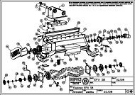
V-<strong>Maxx</strong> <strong>8500</strong> Auger Drive AssemblyParts BreakdownKey Part No. Description Qty. D 4122 3/8"-16 x 2" Hex Bolt 4 D 6584 3/8" Nylock Nut w/Serrated Head 8 D 6159 10-32 x 2" HH Machine Screw 2 D 6132 1/4"-20 x 3/4" Hex 2 D 6528 1/2"-13 Serrated Hex Head 6 D 6158 10-32 Lock Nut 2 D 6583 5/16"-18 x 2" SS HWH 2 D 6803 Rear Rail Assembly 1 D 6810 3/8-16 x 1" Carriage Bolt 2 D 6812 Front Bearing Plate 1 D 6813 Rear Bearing Plate 1 D 6814 Bearing Cover 1 D 6816 Variable Pitch Auger 1 D 6825 12 Volt High Output Motor 1 D 6826 80:1 Auger Transmission 1 D 6831 Auger Motor Cover 1 D 6842 Trans/Auger Drive Coupler 2 D 6843 Urethane Spyder 1 D 6845 Auger Bearing 2 D 6873 3/16" Key Stock 3 D 6875 3/8"-16 x 1-1/2" Carriage Bolt 4 D 6877 #8 x 3/4 Self Drilling HWH 7 D 6452 3/8"-16 x 1" Type F HH TCS 8Auger DriveAssembly© Trynex International 2006 L1159 4 — 11
V-<strong>Maxx</strong> <strong>8500</strong> Spinner Drive AssemblyParts BreakdownKey Part No. Description Qty. D 4121 3/8" - 16 x 1" Hex Bolt 4 D 4289 1/4" Nylock Nut 7 D 6107 8:1 Ratio Transmission 1 D 6819 Motor Enclosure Cover 1 D 6467 Push Fastener 6 D 6132 1/4"-20 x 3/4" HWH Serrated TCS 4 D 6133 5/16"-18 x 1/2 Hex Bolt 1 D 6131 1/4-20 x 1/2" SS HWH Serrated TCS 4 D 6135 #10-32 x 5/8" Hex Machine Screw 2 D 6136 #10 Lock Washer 2 D 6524 5/16-18 x 1-1/2" Bolt 8 D 6138 5/16" Nylock Nut 8 D 6162 24" Power Cable 1 D 6232 Motor Drive Coupler 1 D 6827 12 Volt High Output Motor 1 D 6823 5 Flite Urethane Spinner 1 D 6832 Material Chute 1 D 6833 Material Deflector 1 D 6817 Drive Enclosure Shroud 1 D 6818 Spinner Motor Enclosure 1 D 6820 Heavy Duty Spinner Tubular Guard 1 D 6563 Spinner Drive Pin 1 D 4134 Drive Pin Clip 1 D 6824 Spinner Hub Weldment 1 D 6854 1/4"-20 x 1" HWH Serrated SS 3Complete DriveAssembly (D6850)© Trynex International 2006 L1159 4 — 13
V-<strong>Maxx</strong> <strong>8500</strong> Hopper AssemblyParts Breakdown4 — 14L1159 © Trynex International 2006
V-<strong>Maxx</strong> <strong>8500</strong> Hopper AssemblyParts BreakdownKey Part No. Description Qty. D 4121 3/8" - 16 x 1" Hex Bolt 5 D 4124 3/8" Nylock Nut 17 D 4313 3/8" Lock Washer 8 D 6138 5/16" Nylock Nut 10 D 6509 Top Screen Hold Down 4 D 6815 Bolt Plate 2 D 6515 Heavy Duty Vibrator 1 D 6800 V-<strong>Maxx</strong> Hopper 1 D 6808 Inverted V Assembly 1 D 6807 Discharge Baffle 1 D 6809 Salt Baffle 1 D 6811 Inverted V Backing Plates 4 D 6848 One Piece Top Screen 1 D 6874 #14 x 1.5" HWH Self Driller 8 D 6847 Baffle Extension 1HopperAssembly© Trynex International 2006 L1159 4 — 15
V-<strong>Maxx</strong> <strong>8500</strong> Frame AssemblyParts Breakdown 4 — 16L1159 © Trynex International 2006
V-<strong>Maxx</strong> <strong>8500</strong> Frame AssemblyParts BreakdownKey Part No. Description Qty. D 4121 3/8" - 16 x 1" Hex Bolt 4 D 4125 3/8" Flat Washer 4 D 4124 3/8" Nylock Nut 4 D 6528 1/2-13 x 1" Serrated Hex Bolt 16 D 6536 Right Stop Bracket 1 D 6537 Left Stop Bracket 1 D 6801 Side Frame Weldment 2 D 6804 Upper/Lower Front Rail 2 D 6805 Rear Apron 1 D 6806 Auger Motor Trans Support 1FrameAssembly© Trynex International 2006 L1159 4 — 17
Vehicle Harness Wiring InstructionsStep 1: Take harness assembly and route from the rear of the vehicle to the front. Route harness along frame and attach to frame holesand frame supports. It is not recommended to attach to fuel or brake lines for obvious reasons. Do not route close to exhaust system orengine, even though Trynex uses high temperature wiring, it still could melt under extreme heat and short the spreader electrical system, aswell as the vehicle electrical system.Step 2: Mount rear plug on bumper using supplied bolts, locate towards the center of the bumper to reduce the amount of debris the tireswill throw to the rear. Important: Apply a small amount of dielectric grease to the plug. Also try to mount so plug faces upward tohelp keep plugs tightly sealed.Step 3: Secure harness from the rear to the front using heavy duty ty-wraps or frame clips along the frame and lighter duty ty-wrapseverywhere else.Step 4: Layout harness portion that connects to the battery along the fire wall and fender well. Do not connect power leads to battery yet.Drill a 3/4" hole in the fire wall, or use existing access hole, for the control portion of the harness and route connector and harness throughhole. Be sure to check the area on the other side of the fire wall to make sure you are not going to drill into the vehicle harness or a controlmodule. Generally you can drill on either side of the steering wheel for a good location.Step 4A: The power harness from control box to battery will need to be routed from the inside of the cab to the battery – this results fromthe large high amperage connector. Route leads with lugs to battery — do not connect power at this time.Step 5: Connect harness to the back of the controller and mount to a suitable location. NOTE: You may want to contact customer beforemounting controller, some prefer not to have holes drilled into the dashboard. Ty-wrap loose controller harness and move to the enginecompartment. Do not mount close to any heater vents.Step 6: Connect power leads to the battery: Red + Positive, Black – Negative, always connect to the primary battery if using a dual batterysystem, secure loose loom to any other large or medium vehicle harness with medium duty ty-wraps this will secure wiring harness.Step 7: Install ignition wire to an auxiliary circuit that is hot when the ignition key is turned to ON position or direct to the battery. Thiswire is 60" long and has a female terminal attached to it. This wire will plug into back of controller. This wire must be installed in order forcontroller to work.Step 8: Push the ON/OFF button on the controller to check for power, when that has been confirmed turn power OFF. The electrical portionof the installation is complete.NOTE: If adding an inline fuse, use a 60 amp slow blow fuse.4 — 18L1159 © Trynex International 2006
V-<strong>Maxx</strong> <strong>8500</strong> Electrical SystemParts BreakdownKey Part No. Description Qty. D 6136 #10 Washer 4 D 6158 #10 Lock Nut 4 D 6513 CHMSL Vehicle Harness 1 D 6514 CHMSL Light Assembly 1 D 6529 #10 Black Oxide Machine Screw 2 D 6834 Control Floor Mounting Bracket 1 D 6835 V<strong>Maxx</strong> Dual Control 1 D 6836 27' Vehicle Harness 1 D 6837 Control Power Cable 2 D 6838 Spreader Harness 1 D 6839 6 GA. Breaker Wire 1 D 6840 80 AMP Resetable Breaker 1 D 6874 #14 x 1.5" HWH Self Driller 4 D 6118 Dust Cap 1© Trynex International 2006 L1159 4 — 19
D6835 ControlAugerRed Positive (+)AugerBlack Negative (–)20 AmpCircuit Breaker20BlackNegative (–)OUTPUTPre-Wetting SystemOutput Data PortSpinnerRed Positive (+)RedPositive (+)VibratorRed Positive (+)VibratorBlack Negative (–)SpinnerBlack Negative (–)MAIN INPUTPOWERD6837 Control Power Cable with D6840 BreakerPositiveWhite with Red Tracer (+) to batteryRing TerminalNegativeBlack (–) to batteryRing TerminalKey Part No. DescriptionQty. D 6837 Control Power Cable 2 D 6839 6 GA. Breaker Wire 1 D 6840 100 AMP Resetable Breaker 1* NOTE:A) Leads must only be attached to battery.B) 100 Amp breaker must be inserted.Connect to controlmating half4 — 20L1159 © Trynex International 2006
D6838 Spreader Power HarnessCircuit DiagramSPINNERBlue Positive (+)AUGERRed Positive (+)SPINNEROrange Negative (–)VIBRATORYellow Positive (+)AUGERBlack Negative (–)VIBRATORGreen Negative (–)MAIN POWER PLUGSPREADERYellowPositive (+)OrangeNegative (–)GreenNegative (–)BluePositive (+)VIBRATORPOWER PLUGSPINNERPOWER PLUG© Trynex International 2006 L1159 4 — 21
D6836 Vehicle HarnessCircuit DiagramCONTROLOUTPUT PLUGBUMPERPLUGSPINNER/VIBRATORCIRCUIT AndersonBlock(4) PosAUGERCIRCUITOUTPUTAndersonBlock(2) PosAUGERBlack Negative (–)AUGERRed Positive (+)SPINNEROrange Negative (–)VIBRATORGreen Negative (–)VIBRATORYellow Positive (+)SPINNERBlue Positive (+)SPINNER OUTPUTBlue Positive (+)VIBRATOR OUTPUTYellow Positive (+)VIBRATOR OUTPUTGreen Negative (–)SPINNER OUTPUTOrange Negative (–)RedPositive (+)BlackNegative (–)* NOTE: Reference Bumper Plug for Color Code4 — 22L1159 © Trynex International 2006
Center High Mount Stop Lamp (CHMSL)• With spreader mounted on vehicle, plug vehicle (CHMSL) harness into spreader stop lamp harness.• Using supplied harness clamps and screws, route harness along side wall lower corner or so that harness will be out of the way whenspreader is not in use.• Locate vehicle ground wire and stop lamp power wire at rear of vehicle. Use supplied wire taps to connect harness to vehicle electricalsystem. Once wire taps are installed check to make sure stop lamp works when brake pedal is pressed. Properly complete installationby tying up any loose wires with ty-wraps, also add electrical tape over both connections to insure a solid electrical connection. Somenewer trucks have auxiliary stop lamp power leads already at the rear for these types of applications.CHMSL Spreader Harness(installed on Spreader from factory)Key Part No. Description Qty. D 6158 #10 Lock Nut 2 D 6514 CHMSL Spreader Harness 1 D 6529 #10 Black Oxide Screw 2Route along bed.CHMSL Vehicle HarnessBlack Ground (–)White Positive (+)Splice into vehicle harness stoplamp/CHMSL circuit.Key Part No. Description Qty.D 6234 Butt Connectors 2 D 6513 CHMSL Vehicle Harness 1D 6523 Scotch Locks 2D 6560 Hex Head Screw 4D 6561 Cable Mounts 4© Trynex International 2006 L1159 4 — 23
V-<strong>Maxx</strong> <strong>8500</strong> Mounting SystemStrapping TechniquesFigure 1Cross Left Upper toRight LowerCross Right Upper toLeft Lower.Stop Bars & Strap from rear ofvehicle to front corner.Ratchet Straps Figure 2: Frame Mounting BoltsThrough floor/bedmounting bolts.Key Part No. Description Qty. D 4116 1/2" - 13 x 1-1/2" Hex Bolt 4 D 4119 1/2" Flat Washer 4 D 4120 1/2" Lock Nut 4 D 4121 3/8 - 16 x 1" Hex Bolt 4 D 4124 3/8" Lock Nut 4 D 6503 Ratchet Strap 4 D 6536 Adj. Stop Bracket RT 1 D 6537 Adj. Stop Bracket LT 1 D 6855 Tarp 14 — 24L1159 © Trynex International 2006
V-<strong>Maxx</strong> <strong>8500</strong>Mounting InstructionsStep 1: Remove tailgate from pickup bed.Step 2: Load spreader on to truck bed and mount spinner assembly.Step 3: Slide spreader forward until deflector/chute assembly makes contact with vehicle. Then, slide spreader back approx. 1" to allow forproper clearance.Step 4: Install stop bars using supplied hole patterns (see Fig.2). To achieve the best position, you may need to drill additional holes inbracket in order to properly position spreader.Step 5: Now that the spreader is located front to back, you will now center it left to right. Looking at the inside front and rear corner area ofthe lower frame area, you will notice (4) holes in the bottom of the frame. Using a paint pen or similar marking device, mark hole locations.Step 6: Before drilling holes, look beneath the approximate area where each hole will be located. Make sure there are no vehiclecomponents that will be in the path of the drill before doing this step. If there are interferences, you can relocate holes as needed makingsure there are at least two forward and two rearward of the front to back centerline.Step 7: Install and tighten all (4) bolts.Step 8: Install ratchet straps (see V-<strong>Maxx</strong> <strong>8500</strong> Mounting System: Strapping Techniques). It is very important for everyone’s safety thisstrapping method be used as the standard mounting procedure. (Do not use ratchet straps exclusively.)Step 9: Connect the spreader power cord to vehicle main power plug mounted at rear of vehicle (see Electrical Installation).Step 10: Connect Center High Mount Stop Lamp (CHMSL) cord from the spreader to mating half attached to vehicle (see ElectricalInstallation).© Trynex International 2006 L1159 4 — 25
Operating the SpreaderPREPARATIONCAUTION –Sweep area clear of foreign objects or obstacles that could cause personal injury. Keep other persons, children, or t animals ouof the area to be spread.SPREADER LOADINGWARNING –Do not overload vehicle. Use chart below to calculate weight of material. Weights of material are an average for . dry materialsMaterialRock SaltSand/Salt MixWeight Per Cubic Ft.35-40 lbs.95-120 lbs.• Be sure to comply with manufacturer’s maximum gross vehicle weight ratings.• Warning– Never leave materials in hopper for long periods of time as salt is hygroscopic and will attract atmospheric moisture andharden up. When spreading sand mix, a 1:1 ratio for Sand/Salt mix is recommended to prevent the material from freezing.SPREADING TIPS• Never exceed 10 m.p.h. when spreading.• For a wider pass, increase spinner speed.• For a heavier pass, drive slower, or increase auger speed.• Never operate spreader near pedestrians.• Spread ice melters with the storm to prevent unmanageable levels of ice.• Calculate spread pattern when near vegetation.V-MAXX <strong>8500</strong> CONTROL OPERATION• The Dual Variable Speed Control has dual finger-tip dials for maximum performance, digital system status with warning tion and protecbuilt-in Vibrator Switch.• To start, press power switch on controller and spreader will accelerate to speed set on spinner and auger dials.• To stop, press power switch on controller to off position.• Speed of auger and spinner may be adjusted separately to get desired flow and spread distancefrom spreader.• The Vibrator Switch is needed for dense material or to increase the flow to the auger. This eliminates bridging in of hopper. material• In case spreader becomes jammed, it will go into an auto-reverse program to free itself. Auger display will show (AR) while trying toclear obstruction.4 — 26L1159 © Trynex International 2006
Operating the Spreader (continued)BAFFLE INSTRUCTIONS• The V-<strong>Maxx</strong> <strong>8500</strong> uses a dual baffle design over the auger area.This baffle (D6809) is used for dry bulk materials. The baffle isdesigned to reduce the risk of leakage with clean/dry free-flowingmaterials. If the material you are using is damp/wet, you may needto remove baffle (D6809). This will allow for more un-restricted flowof materials and possible bridging.• WARNING: Always disconnect power source before attempting toremove material baffle.• The main baffle assembly (D 6808) MUST never be removed fromits original factory installed position unless the unit is being servicedor installing Optiflow Kit.D6809BAFFLE EXTENSION INSTRUCTIONS• The Baffle Extension is installed at the time of assembly. The mainpurpose of this baffle is to keep dry, free-flowing material fromleaking out.• If you plan on using damp/wet materials, you should remove thisbaffle by removing the self-drilling screws.• If you are using a sand/salt mixture, remove baffle extension.Key Part No. Description Qty. D 6847 Salt Baffle Extension 1 D 6807 Discharge Baffle 1 D 6874 #14 x 1-1/2" TEK w/Neo Washer 2© Trynex International 2006 L1159 4 — 27
Operating the Spreader (continued)WARNING PROTECTION• If audible beeping occurs, read display to identify problem. If display reads “OL” (overload) or “OH” (overheat). Shut controller down andcarefully clear jammed auger. If display reads “E1“ this means there is a dead short in system. Do not use until problem is corrected. Ifdisplay reads “E 0” this means that the motor is not getting any power. Check all connections. If display reads “LB” the vehicle batteryis extremely low (possibly caused by a poor or corroded connection) and could damage the system.• If there are any problems while operating the spreader, refer to Troubleshooting Guide.AUTO-REVERSE “AR” FUNCTION• If your controller displays “OL” this could indicate a jammed auger.• To engage the Auto-Reverse “AR” function:Step 1: Shut the Main Power Switch OFF for 3 seconds.Step 2: Turn the Main Power Switch ON. When the machine starts back up the “AR” sequence will automatically start and the augerwill reverse for several rotations to clear the jam.• After a pause of several moments, the auger will automatically return to correct rotation.• If the jam is still not cleared, the controller will again display “OL”.• You may repeat Steps 1 & 2 for a second and third time.• If after the third try the controller displays “OL” — you must extract the material that is causing the problem.• Follow all warning directions when clearing jams.4 — 28L1159 © Trynex International 2006
TroubleshootingWhenever service is necessary, your local SnowEx Dealer knows your Spreader best. Take your Spreader to your local dealer for anymaintenance or service needs on your unit. If this is not possible, the Troubleshooting Guide below may assist you in identifying the problem.Warning: First read all warning instructions and safety messages before servicing your spreader.Preliminary Checks• Be sure all electrical connections are tight and clean.• Be sure nothing is jammed in the hopper.PROBLEM POSSIBLE CAUSE SOLUTIONMotor doesn’t run.Loose electrical connections.Check all connections.Controller shut down.Material not flowingfrom hopper.Audible alarm beeping anddisplay shows OL or OH.Audible alarm beepingdisplay shows E1.Audible alarm beepingdisplay shows EO.Audible alarm beepingdisplay shows LB.Blown Fuse.Motor Seized.Jammed auger.Poor electrical connections.Electrical short.Controller failure.Empty hopper.Wet material.Frozen or coarse material.Spinner not turning.Auger loose on shaft.Vibrator not working.Jammed auger, overload shut down.Short in system.Motor is not getting power.Vehicle battery is extremely low,or a poor connection exists.Replace fuse.Replace motor.Carefully clear jammed material.Clean or replace connectors.Use dielectric grease.Check electrical connections.Check for bare wires.Replace controller.Fill hopper.Replace with dry material.Replace material.Check drive assembly.Tighten locking bolt on the side of the auger. There is a flatmachined on the driver shaft. Align the auger with this flatand tighten the bolt.Replace vibratorTurn off for three seconds, then restart. If shut downcontinues, turn off controller. Clear debris and lumps fromauger areas.Turn off. Do not use until problem is corrected.Turn off. Check all connections.Turn off. Charge battery.© Trynex International 2006 L1159 4 — 29
TroubleshootingV-<strong>Maxx</strong> <strong>8500</strong>SPREADERDOES NOT RUNCONTROLLER TURNS ONBEEP SHUTS OFFDISPLAYS ERROR CODEOL CODEDEFINITION:AMP DRAWTOO HIGHJAMMED MATERIALSWITCH OFF & ONFOR AUTO-REVERSEFUNCTIONCLEAR JAMBAD MOTORCHECK WITH TEST KITTEST 4 TO 20 AMP DRAWNO LOAD GOOD20+ AMP DRAWNO LOAD BADBAD TRANSMISSIONCHECK WITH TEST KITTEST TURN SHAFTBY HANDSHOULD TURN FREELYCORROSIONREPLACE ALLCORRODEDCONNECTIONSDON'T FORGETUSE DIELECTRICGREASEBAD CONTROLLERCHECK WITH TEST KITEO CODEDEFINITION:OPEN CIRCUIT BETWEENMOTOR AND CONTROLLERSPREADER UNPLUGGEDPLUG IN SPREADERMOTOR POWER CORDDISCONNECTEDINSIDE DRIVE ASSEMBLYOPEN ACCESS COVERAND PLUG TOGETHERBREAK INWIRING HARNESSCHECK WITH TEST KITREPLACE HARNESSLB CODEBAD ELECTRICALCONNECTIONCORROSIONREPLACE ALL CORRODEDCONNECTIONSLOOSE CONNECTIONTIGHTEN OR REPLACELOW BATTERYLESS THAN 12 VOLTOUTPUTLOAD TEST BATTERYE1 CODEDEAD SHORTIN MOTOR CIRCUITREPLACEAFFECTEDCOMPONENTSALL OTHERCODESCHECK HARNESSFOR SPLICED INACCESSORYBAD CONTROLLERCHECK WITH TEST KITREPLACEON/OFF SWITCHLIGHTS NO DISPLAYCHECK POWERTO BLUE WIREBAD CONTROLLERCHECK WITH TEST KITNOTHING HAPPENSNO DISPLAYON/OFF SWITCH WILLNOT LIGHT UPCHECK POWER SOURCETO CONTROLLERBAD CONTROLLERCHECK WITH TEST KIT4 — 30L1159 © Trynex International 2006
TroubleshootingV-<strong>Maxx</strong> <strong>8500</strong>MATERIALFREE FLOWSCHECK BAFFLELENGTH18" CORRECTMATERIAL ISSUECHECK BAFFLEPOSITIONSHOULD TOUCH HOPPERON 3 SIDESMATERIAL ISSUEMATERIALDOES NOT FLOWMATERIALOBSTRUCTIONREMOVEOBSTRUCTIONMATERIAL ISSUEAUGER RUNSBACKWARDSRUN 12 VOLT TOAUGER CIRCUIT ONSPREADER POWER CORDAUGER RUNSPROPER DIRECTIONREPLACE VEHICLEHARNESSTURN ONVIBRATORAUGER RUNSBACKWARDSCHECK CONNECTIONSAT AUGER MOTORFOR REVERSE POLARITYPOLARITY CORRECTREPLACE SPREADERHARNESSSLOWMATERIALFLOWTURN ONVIBRATORINCREASEAUGER SPEEDMATERIAL ISSUE* Spreader capable of speading most granular bulk material, includingcoarse 50/50 salt/sand mix.NOTE: Optional Optimum Flow Kit Available, To Increase Material Flow© Trynex International 2006 L1159 4 — 31
Spreader Maintenance• WARNING – When servicing is necessary, perform it in a protected area. Do not use power tools in rain or snow because of danger ofelectrical shock or injury. Keep area well lighted. Use proper tools. Keep the area of service clean to help avoid accidents.• WARNING – Disconnect electricity to spreader before servicing.• CAUTION – The controller is a solid state electronic unit and is not serviceable. Any attempt to service will void warranty.• CAUTION – There are no serviceable parts in the motor/transmission assembly. Any attempt to service will void warranty.• CAUTION – When replacing parts use only original manufacturer’s parts. Failure to do so will void warranty.• Use diaelectric grease on all electrical connections to prevent corrosion at the beginning and end of the season and each time powerplugs are disconnected.• Gently wash unit after each use to prevent material build-up and corrosion.• CAUTION – When pressure washing motor enclosure area stay at least 36'' away from all electrical items.• Paint or oil all bare metal surfaces at the end of the season.• Apply small amount of light oil to latches as needed.• If motor cover is removed for any reason, use silicone sealant to ensure weather proofing of enclosure.• Grease bearings after every 20 hours use.• After first use, tighten all nuts and bolts on spreader and mount.• WARNING: Never remove spreader with material in hopper.4 — 32L1159 © Trynex International 2006
Useful FormulasDetermining Vehicle PayloadMaterial TypeExample:Coarse Salt – DryEquipment installed when vehiclewas weighed6'/8' V-<strong>Maxx</strong> Vee <strong>8500</strong> ProFront Gross Axle Weight Rating(RGAWR)Rear Vehicle Weight Rating(GVWR) (lb.)8600Gross Vehicle Weight (GVW) (lb.) (empty)– 6500––––Payload Available (lb.)= 2100====Material Weight (lb./cu. yd.)÷ 1431÷÷÷÷Maximum Volume (cu. yd.)= 1.47====Maximum Height (approximate) (in.)24"Loaded Front Gross Axle Weight(FGAW) (lb.)Loaded Rear Gross Axle Weight(RGAW) (lb.)Loaded Gross Vehicle Weight (GVW) (lb.)Torque ChartWhen tightening fasteners, refer to the Torque Chart below forthe recommended fastener torque values.Recommended Fastener Torque Chart (ft.-lb.)SIZESAEGrade 2SAEGrade 5SAEGrade 8Material WeightsRefer to the table below for the weight per cubic yardof common spreading materials.MATERIALWEIGHT(lb. per cubic yard)1/4-205/16-183/8-163/8-247/16-141/2-139/16-125/8-113/4-107/8-91-8611192430456693150202300918314650751101502503785831328466875115165225370591893Fine Salt – DryCoarse Salt – DrySand/Salt Mix – Dry (50/50)Cinders2,0251,4312,7001,080Metric Grade 8.8 (ft.-lb.)SIZE TORQUE SIZE TORQUEM 6M 8M 1071735M 12M 14M 166095155These torque values apply to mount assembly fasteners exceptthose noted in the instruction.© Trynex International 2006 L1159 4 — 33
WarrantyLimited WarrantySnowex products are warranted for a period of two years from the date of purchase againstdefects in material or workmanship under normal use and service, subject to limitations detailedbelow. Warranty period of two years begins on the date of purchase by the original retail user.The WARRANTY REGISTRATION CARD must be returned to the manufacturer for this warrantyto become effective. This warranty applies to the original retail purchaser only. This warranty doesnot cover damages caused by improper installation, misuse, lack of proper maintenance, alterationsor repairs made by anyone other than authorized Trynex dealers or Trynex personnel. Due to thecorrosive properties of the materials dispensed by spreaders, Trynex does not warrant againstdamage caused by corrosion. Warranty claims by the user must be made to the dealer from wherethe product was purchased, unless otherwise authorized by Trynex. Trynex reserves the right todetermine if any part is defective and to repair or replace such parts as it elects. This warranty doesnot cover shipping costs of defective parts to or from the dealer.LIMITATION OF LIABILITYNeither Trynex, nor any company affiliated with it, makes any warranties, representations forpromise as to the performance or quality other that what is herein contained. The liability of Trynexto the purchaser for damages arising out of the manufacture, sale, delivery, use or resale of thisspreader shall be limited to and shall not exceed the costs of repair or replacement of defectiveparts. Trynex shall not be liable for loss of use, inconvenience or any other incidental, indirect orconsequential damages, so the above limitations on incidental or consequential damages may notapply to you.NO DEALER HAS AUTHORITY TO MAKE ANY REPRESENTATION OR PROMISE ON BEHALF OFTRYNEX INTERNATIONAL, OR TO ALTER OR MODIFY THE TERMS OR LIMITATIONS OF THISWARRANTY IN ANY WAY.4 — 34L1159 © Trynex International 2006
Warranty Registration and Customer SurveyTo initiate the warranty on your new SnowEx spreader and assure prompt warranty service, please complete thefollowing warranty registration and customer survey, sign and mail it back to the factory within 30 days of purchase.1) Date of Purchase:2) Name:Address:Phone:3) SnowEx Model Purchased: Serial Number:4) Is this your first Trynex Spreader? ❏ Yes ❏ No5) What type of vehicle are you using with your Spreader?Make Model Year6) What type of material are you using in your spreader?7) SnowEx Dealer Name:SnowEx Dealer Address:SnowEx Dealer Phone:8) Does your Trynex Dealer stock Trynex replacement Parts? ❏ Yes ❏ No ❏ I don’t know9) Do you feel your Trynex Dealer sold you the correct product for your needs/application? ❏ Yes ❏ No10) How would you rateyour overall satisfactionwith your SnowEx Dealer?❏VerySatisfied❏Satisfied❏SomewhatSatisfied❏SomewhatDissatisfied❏Dissatisfied❏VeryDissatisfied11) How would you rateyour overall satisfactionwith your SnowEx Product?❏VerySatisfied❏Satisfied❏SomewhatSatisfied❏SomewhatDissatisfied❏Dissatisfied❏VeryDissatisfied12) Would you purchase another Trynex Product? ❏ Yes ❏ No13) Please use the space below to convey your comments and/or suggestions.NOTE: I have read the owner’s manual and all safety precautions and I understand that this equipment could be dangerous if not operatedwith care and under the proper conditions.14) Owner’s signature: XPLEASE FOLD AND SEAL WITH TRANSPARENT TAPE BEFORE MAILING.© Trynex International 2006 L1159 4 — 35
Warm Up towith aFREEFREEWinter Hat!Simply Fill Out YourWarranty Registration andReturn It to the Factory!From:PostageRequiredPost Office willnot deliverwithout properpostage.23455 REGENCY PARK DR.WARREN MI 48089-2667