
Create successful ePaper yourself
Turn your PDF publications into a flip-book with our unique Google optimized e-Paper software.
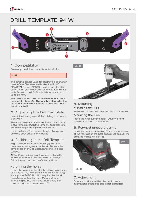
DRILL TEMPLATE 94 W<br />
4<br />
1. Compatibility<br />
Presently the drill template 94 W is valid for:<br />
SL 45<br />
This binding can be used for children’s skis shorter<br />
than 140cm. The standard brake, the SL KID<br />
BRAKE 74 (art.nr. 162 399), can be used for skis<br />
up to 74 mm, for wider skis use the SL KID BRAKE<br />
wide 84 (art.nr. 162 658), which is for skis from<br />
75 to 84 mm.<br />
The Description of the brakes always includes a<br />
number like 74 or 84. This number stands for the<br />
maximum ski width in the brake area and not in<br />
the ski center!!!<br />
2. Adjusting the Drill Template<br />
Unlock the locking lever (1) by rotating it counterclockwise.<br />
Place the template on the ski. Place the ski boot<br />
in the template. Push the template together until<br />
the violet stops are against the sole (2).<br />
Lock the lever (1) to prevent length change and<br />
take the boot out of the template.<br />
3. Positioning of the Drill Template<br />
Align the boot midsole indicator (3) with the<br />
midsole mounting mark on the ski. Be sure the<br />
template is evenly seated against the ski’s top<br />
surface.<br />
Note: Some ski manufacturers do not use the<br />
center of boot sole location method. Always<br />
follow the ski manufacturer’s instructions.<br />
4. Drilling the holes<br />
If not otherwise specified by the ski manufacturer,<br />
use a 4,1 Ø x 7,0 mm drill bit. Drill the holes using<br />
appropriate TYROLIA drill. If required by the ski<br />
manufacturer, tap the hole. Place a drop of<br />
TYROLIA glue into the holes. It lubricates the<br />
screws and seals the ski. (pict. 12).<br />
2<br />
1<br />
3<br />
pict 12<br />
2<br />
5. Mounting<br />
Mounting the Toe<br />
MOUNTING/ 23<br />
Place toe unit over the holes and fasten the screws.<br />
Mounting the Heel<br />
Place the heel over the holes. Drive the front<br />
screws first, then the rear ones.<br />
6. Forward pressure control<br />
Latch the boot in the binding. The indicator located<br />
at the rear end of the heel piece must be over the<br />
grooved marks (6) (pict 13).<br />
SL 45<br />
7. Adjustment<br />
Check to make sure that the boot meets<br />
international standards and is not damaged.<br />
❷6<br />
5<br />
pict 13