Heat-A-Ventlite® (with Night Light) - Home Depot
Heat-A-Ventlite® (with Night Light) - Home Depot
Heat-A-Ventlite® (with Night Light) - Home Depot

Create successful ePaper yourself
Turn your PDF publications into a flip-book with our unique Google optimized e-Paper software.
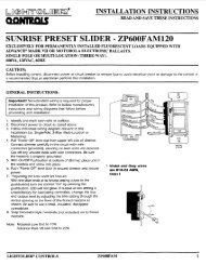
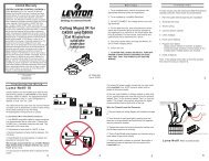
MOUNTING THE HOUSING1. Locate housing between joists.2. Refer to Figure 5. Using nails, secure hanger bars to joist.NOTE: The hanger bar brackets are adjustable.Allowing for the thickness of the finished ceiling,mount hanger bars so that edge of housing will beflush <strong>with</strong> the finished ceiling.3. Adjust brackets as required. Tighten brackets.INSTALLING THE DUCTWORK1. Refer to Figure 5. Install duct collar.2. Using 4" round duct, connect duct to collar and tapeconnection.INSTALLING THE SWITCH1. Install double-gang switch box in chosen location.2. Refer to Figure 6. Run wiring and make wiringconnections.3. Use supplied screws to secure switch bracket assemblyto switch box.4. Using supplied screws, secure wall plate to switch bracket.MOUNTING THE GRILLE ASSEMBLY1. Refer to Figure 7. Place the reflector into the grille.2. Refer to Figure 8. Insert light plug and night light plug intoreceptacles.3. Refer to Figure 7. Using two provided screws, securegrille and reflector to housing.4. Install 100 watt (maximum) light bulb into light socket.5. Install 7 watt (maximum) C-7 candelabra type bulb intonight light socket.6. Refer to Figure 9. Snap lens into place.HEATERJUNCTION BOXBLKBLULIGHTVENTWHTWHTWHTWHTHEATER(WHITE)NIGHTLIGHTREDBLKTINSTALLING AND CONNECTING THE WIRINGRefer to Figure 6.All wiring must comply <strong>with</strong> local codes and unit mustbe properly grounded.1. Using 12-gauge wire, run 120vAC, 60 Hz wiring (<strong>with</strong>ground) from a power source to the wall switch location.The unit must be wired on a separate 20 Amp circuit.2. Run wiring from switch location to housing as shown in thewiring diagram.3. Make wiring connections as shown in wiring diagram.4. Replace junction box cover. Slide slotted hole in cover overscrew. Tighten screw securely.5. Secure wire cover <strong>with</strong> one screw.6. Insert heater and ventilator plugs into proper receptaclesas shown.SWITCHBOXVENTLIGHTNOTE:WHEN THERMOSTATOR TIMER IS USED,CONNECT AT TBLACK120vACLINEWHITEGROUNDHEATNIGHTLIGHTFIGURE 6DUCT COLLARGRILLEREFLECTOR(LENS OMITTEDFROM DRAWINGFOR ILLUSTRATIVEFIGURE 5PURPOSES)FIGURE 7