Heat-A-Ventlite® (with Night Light) - Home Depot
Heat-A-Ventlite® (with Night Light) - Home Depot
Heat-A-Ventlite® (with Night Light) - Home Depot

Create successful ePaper yourself
Turn your PDF publications into a flip-book with our unique Google optimized e-Paper software.
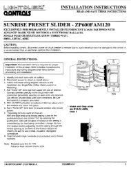
INSTALLATION INSTRUCTIONSREAD & SAVE THESE INSTRUCTIONS!<strong>Heat</strong>-A-Ventlite ®(<strong>with</strong> <strong>Night</strong> <strong>Light</strong>)MODEL: 99659 3 ⁄4"7 3 ⁄4"FOR BEST RESULTSIn a new construction site, install the housing (complete<strong>with</strong> heater and ventilator) during rough-in construction of thebuilding. The light assembly and the grille should be installedwhen the finished ceiling is in place.Installation in an existing, finished building requires anaccessible area (attic or crawl space) above the plannedlocation. See “INSTALLATION IN EXISTINGCONSTRUCTION.”Do not install closer than 12 inches to a vertical surface.Do not install over tub or shower enclosure.UNIT DIMENSIONSRefer to Figure 1 for housing's dimensions.NOTE: If there will be a finished second floor above,the Model 9965 housing requires a minimum of 2" x 8"joist construction for mounting.14"FIGURE 1WIRING AND DUCTWORK1. Run the required wiring during rough-in stage ofconstruction.2. Total connected load: 1730 watts.3. Plan to run 120vAC, 60 Hz wiring (<strong>with</strong> ground) on aseparate 20 Amp circuit from a power source, throughthe provided wall switch, to the housing's junction box.See wiring diagram.4. Use 4" round duct.INSTALLATION INNEW CONSTRUCTIONPREPARATION1. Install hanger bar brackets in slots in housing. (See Fig. 3)Do not tighten completely to allow bars to be inserted.2. Refer to Figure 2. Insert hanger bars into brackets.3. Refer to Figure 3. Slide hanger bar brackets down to endof slot closest to outside edge of housing. Tighten bracketsin this position.4. Refer to Figure 4. Remove junction box cover byremoving one screw.5. Refer to Figure 4. Remove appropriate wiring knockout(s)and install approved box connector(s).ADJUSTMENTSLOTJUNCTIONBOXCOVERHANGER BARSFIGURE 2KNOCKOUTSFIGURE 3 FIGURE 4
MOUNTING THE HOUSING1. Locate housing between joists.2. Refer to Figure 5. Using nails, secure hanger bars to joist.NOTE: The hanger bar brackets are adjustable.Allowing for the thickness of the finished ceiling,mount hanger bars so that edge of housing will beflush <strong>with</strong> the finished ceiling.3. Adjust brackets as required. Tighten brackets.INSTALLING THE DUCTWORK1. Refer to Figure 5. Install duct collar.2. Using 4" round duct, connect duct to collar and tapeconnection.INSTALLING THE SWITCH1. Install double-gang switch box in chosen location.2. Refer to Figure 6. Run wiring and make wiringconnections.3. Use supplied screws to secure switch bracket assemblyto switch box.4. Using supplied screws, secure wall plate to switch bracket.MOUNTING THE GRILLE ASSEMBLY1. Refer to Figure 7. Place the reflector into the grille.2. Refer to Figure 8. Insert light plug and night light plug intoreceptacles.3. Refer to Figure 7. Using two provided screws, securegrille and reflector to housing.4. Install 100 watt (maximum) light bulb into light socket.5. Install 7 watt (maximum) C-7 candelabra type bulb intonight light socket.6. Refer to Figure 9. Snap lens into place.HEATERJUNCTION BOXBLKBLULIGHTVENTWHTWHTWHTWHTHEATER(WHITE)NIGHTLIGHTREDBLKTINSTALLING AND CONNECTING THE WIRINGRefer to Figure 6.All wiring must comply <strong>with</strong> local codes and unit mustbe properly grounded.1. Using 12-gauge wire, run 120vAC, 60 Hz wiring (<strong>with</strong>ground) from a power source to the wall switch location.The unit must be wired on a separate 20 Amp circuit.2. Run wiring from switch location to housing as shown in thewiring diagram.3. Make wiring connections as shown in wiring diagram.4. Replace junction box cover. Slide slotted hole in cover overscrew. Tighten screw securely.5. Secure wire cover <strong>with</strong> one screw.6. Insert heater and ventilator plugs into proper receptaclesas shown.SWITCHBOXVENTLIGHTNOTE:WHEN THERMOSTATOR TIMER IS USED,CONNECT AT TBLACK120vACLINEWHITEGROUNDHEATNIGHTLIGHTFIGURE 6DUCT COLLARGRILLEREFLECTOR(LENS OMITTEDFROM DRAWINGFOR ILLUSTRATIVEFIGURE 5PURPOSES)FIGURE 7
INSTALLATION INEXISTING CONSTRUCTIONIn an existing, finished building, installation of the <strong>Heat</strong>-Vent-<strong>Light</strong> Combination requires an accessible area (attic orcrawl space) above the planned location. If the location thathas been chosen for installation has a finished floor above it,be certain there is sufficient space available to install thehousing and make the necessary duct connection.PLANNINGReview “INSTALLATION IN NEW CONSTRUCTION” andfollow all instructions that apply.CAUTION: Check the area above the planned locationto make sure that:(1) Ducting can be installed.(2) Wiring can be run to the planned location.(3) No wiring or other obstructions might interfere <strong>with</strong>the installation.INSTALLATION1. The housing must be mounted between ceiling joists.2. Refer to Figure 10. Mark ceiling for cutout. Cutoutdimensions: 14 1 ⁄8" long x 9 7 ⁄8" wide. Make cutout in ceiling.3. Follow steps under “PREPARATION” page 1.4. From above, lower housing into the cutout and securehanger brackets. Install duct collar, connect duct, and runwiring through box connectors.5. From below, adjust housing so that it is flush <strong>with</strong> thefinished ceiling.6. Form below, make wiring connections as shown in figure 6.7. Replace junction box cover.8. Insert heater, ventilator, light, and night light plugs intoproper receptacles.9. install grille, reflector and lens.(LENS DETACHEDIN DRAWING FORILLUSTRATIVEPURPOSES)LENSFIGURE 914 1 ⁄8"9 7 ⁄8"WHITEHEATVENTFIGURE 8 FIGURE 10
One Year Limited WarrantyWARRANTY OWNER: NuTone warrants to the original consumer purchaser of its products that such products will be free from defects in materials or workmanship for a periodof one (1) year from the date of original purchase. THERE ARE NO OTHER WARRANTIES, EXPRESS OR IMPLIED, INCLUDING, BUT NOT LIMITED TO, IMPLIEDWARRANTIES OF MERCHANTABILITY OR FITNESS FOR A PARTICULAR PURPOSE.During this one year period, NuTone will, at its option, repair or replace, <strong>with</strong>out charge, any product or part which is found to be defective under normal use and service.THIS WARRANTY DOES NOT EXTEND TO FLUORESCENT LAMP STARTERS OR TUBES, FILTERS, DUCT, ROOF CAPS, WALL CAPS AND OTHER ACCESSORIESFOR DUCTING. This warranty does not cover (a) normal maintenance and service or (b) any products or parts which have been subject to misuse, negligence, accident,improper maintenance or repair (other than by NuTone), faulty installation or installation contrary to recommended installation instructions.The duration of any implied warranty is limited to the one year period as specified for the express warranty. Some states do not allow limitation on how long an implied warrantylasts, so the above limitation may not apply to you.NUTONE’S OBLIGATION TO REPAIR OR REPLACE, AT NUTONE’S OPTION, SHALL BE THE PURCHASER’S SOLE AND EXCLUSIVE REMEDY UNDER THISWARRANTY. NUTONE SHALL NOT BE LIABLE FOR INCIDENTAL, CONSEQUENTIAL OR SPECIAL DAMAGES ARISING OUT OF OR IN CONNECTION WITHPRODUCT USE OR PERFORMANCE. Some states do not allow the exclusion or limitation of incidental or consequential damages, so the above limitation or exclusion maynot apply to you. This warranty gives you specific legal rights, and you may also have other rights, which vary from state to state. This warranty supersedes all prior warranties.WARRANTY SERVICE: To qualify for warranty service, you must (a) notify NuTone at the address stated below or telephone 1/800-543-8687, (b) give the modelnumber and part identification and (c) describe the nature of any defect in the product or part. At the time of requesting warranty service, you must presentevidence of the original purchase date.Date of InstallationBuilder or InstallerModel No. and Product DescriptionIF YOU NEED ASSISTANCE OR SERVICE:For the location of your nearest NuTone Independent Authorized Service Center:Residents of the contiguous United States Dial Free 1-800-543-8687Please be prepared to provide:Product model number • Date and Proof of purchase • The nature of the difficultyResidents of Alaska or Hawaii should write to: NuTone Inc. Attn: Department of National Field Service, 4820 Red Bank Road, Cincinnati Ohio 45227-1599.Residents of Canada should write to: Broan-NuTone Canada, 1140 Tristar Drive, Mississauga, Ontario, Canada L5T 1H9.Rev. 03/2001Product specifications subject to change <strong>with</strong>out notice.Printed in U.S.A., Rev. 03/2001, Part No. 89356
PARTS LISTEFFECTIVEDATEMODEL NUMBERPRODUCTGROUPMAY19999965REVISEDHEATER4101137569121413a15281716913181924121VENTHEAT20NOT A PARTS DEPT.STOCK ITEM22LIGHTNIGHTLIGHT23REF. ORIGINAL *PART DESCRIPTION REPLACEMENTNO. PART NO. PART NO.1 K3132 BEZEL/LENS ASSEMBLY 89340-0002 K9010 GRILLE 89339-0003 K3135 REFLECTOR 89375-0004 K3136 SOCKET-LARGE 35758-0005 K3137 SOCKET-SMALL W/CLIP 35759-0006 K3097 RECEPTACLE-BLACK 66204-0007 K3160 RECEPTACLE-BLUE WIRE 57976-0008 K3096 RECEPTACLE-WHITE 56721-0009 K3094 MOUNTING BRACKET (1) - 4 Required 57117-00010 K3143 DUCT ADAPTOR 30652-000(PLEASE SEE OTHER SIDE)NOTE: Always order bycurrent part number.
REF. ORIGINAL *PART DESCRIPTION REPLACEMENTNO. PART NO. PART NO.11 K3010 HANGER ROD ASSEMBLY (1) 2 Required 85585-00012 K3117 "B" UNIT ASSEMBLY-VENT 86693-00013 K3122 BLOWER WHEEL 82403-00013a 82404 PUSH NUT 82404-00014 K3121 MOTOR (VENT) 89321-00015 K3118 SCROWL (PLASTIC) 2908A-00016 K3102 "B" UNIT ASSEMBLY (HEAT) 89306-00017 K3111 BLOWER WHEEL (HEAT) 66583-00018 K3110 MOTOR (HEAT) 89315-00019 K3112 MOTOR BRACKET 23255-00020 K3360 THERMAL PROTECTOR 1179A-00021 K3107 HEATING ELEMENT 89312-00022 K3146 SWITCH ASSEMBLY COMPLETE - HARDWARE BAG ASSEMBLY 85918-00023 K3147 SWITCH PLATE 85920-00024 K3148 SWITCH DOUBLE - (2 Required) 85921-000* K9012 GRILLE SCREW NOT SHOWN 89323-000NOTE: Always order bycurrent part number.HEATERJUNCTION BOXBLKLIGHTWHTWHTHEATER(WHITE)RED9965 I.I.BLUVENTWHTWHTNIGHTLIGHTBLKTVENTHEATLIGHTNIGHTLIGHTSWITCHBOXNOTE:WHEN THERMOSTATOR TIMER IS USED,CONNECT AT TBLACKWHITEGROUND120vACLINE