R<strong>5700</strong> ACT Wood StoveR-value given - no conversion needed.k-factor is given with a required thickness (T) in inches:FLOOR PROTECTION (Cont’d)How to determine if alternate floor protection materials are acceptable:All floor protection must be non-combustible (i.e., metals, brick, stone, mineral fiber boards, etc.). Any organic materials(i.e., plastics, wood paper products, etc.) are combustible and must not be used. The floor protection specified includessome form of thermal designation such as R-value (thermal resistance) or k-factor (thermal conductivity).PROCEDURE:1. Convert specification to R-value:ALTERNATE MATERIALS WORKSHEETr =1kx TK-factor is given with a required thickness (T) in inches:r-factor is given with a required thickness (T) in inches: R = r x T2. Determine the R-value of the proposed alternate floor protector.i. Use the formula in step (1) to convert values not expressed as “R”.ii. For multiple layers, add R-values of each layer to determine overall R-value.1r = x TK x 123. If the overall R-value of the system is greater than the R-value of the specified floor protector, the alternate is acceptable.EXAMPLE: The specified floor protector should be 3/4 inch thick material with a k-factor of 0.84. The proposed alternate is4” brick with an r-factor of 0.2 over 1/8” mineral board with a k-factor of 0.29.Step (a): Use formula above to convert specification to R-value.r =11x T =k .84x 0.75 = 0.893Step (b): Calculate R of proposed system.4" brick of r = 0.2, therefore: 1/8" mineral board of k = 0.29, therefore:r = 0.2 x 4 = 0.8r = 1brickx 0.125 = 0.431mineral board0.29r total= r brick+ r mineral board= 0.8 + 0.431 = 1.231Step (c): Compare proposed system R total of 1.231 to specified R of 0.893. Since proposed system R total is greater thanrequired, the system is acceptable.DEFINITIONSr =(ft 2 )(hr)( o F)btubtu(in)btu(ft)k = = K x 12 K =r = (ft 2 )(hr)( o F) = 1ft 2 (hr)( o F)ft 2 (hr)( o F)(btu)(in)kPage 250-7090ESeptember 1, 2008
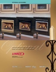
RCHIMNEY HEIGHT/DRAFT<strong>5700</strong> ACT Wood StoveTo be sure that your Quadra-Fire stove burns properly, the chimney draft (static pressure) should be approximately -.10”water column (W.C.) during a high burn and -.04” W.C. during a low burn, measured 6” (152mm) above the top of the stoveafter one hour of operation at each burn setting.NOTE: These are guidelines only, and may vary somewhat for individual installations.Your Quadra-Fire stove was designed for and tested on a 6” (152mm) chimney, 12’-14’ (360-420cm) high, (includes stoveheight) measured from the base of the stove. The further your stack height or diameter varies from this configuration, thepossibility of performance problems exists. In addition, exterior conditions such as roof line, surrounding trees, prevailingwinds and nearby hills can influence stove performance. Your local dealer is the expert in your geographic area and canusually make suggestions or discover solutions that will easily correct your flue problem, allowing your woodstove and itsflue system to operate correctly and provide safe and economical heat for your home.A masonry chimney or a Listed factory-built UL103 HT Class “A” chimney must be the required height above the roof andany other nearby obstructions. The chimney must be at least 3’ (91cm) higher than the highest point where it passes throughthe roof and at least 2’ (61cm) higher than the highest part of the roof or structure that is within 10’ (305cm) of the chimney,measured horizontally. See 2-10-3 Rule below.These are safety requirements and are not meant to assure proper flue draft.We recommend using a minimum total system height of 12' (360cm), measured from the flue collar to the top of thechimney (not including chimney cap).Availability of combustion air: A source of air (oxygen) is necessary in order for combustion to take place. It is important torealize that whatever combustion air is consumed by the fire must be replaced. If you are using room air, the air is replacedvia air leakage that occurs around windows and under doors, etc. However, in most newly constructed houses, mobile homes,or even existing homes that are fitted with tightly sealed doors and windows, the area from which the combustion air is takenis relatively air tight. In these cases, an outside air source must be made available to feed combustion air from outside thehome into the stove. An Outside Air Kit is available for your stove as an option, Part 831-1780. The kit is a requirement formobile home installations. Check with the local authorities in your area for the requirements in your location.2-10-3 RULE3 ft Min(91cm)2 ft Min (61cm)10 ft Min(305cm)warning!always follow chimney connector manufacturer’s instructions for proper installation.chimney connector is to be used only within the room, between the stove and ceiling ORwall. The connector shall not pass through an attic or roof space, closet or similarconcealed space, or a floor, or ceiling. MAINTAIN minimum clearances to combustiblesas REFERENCED on pageS 6, 7, 8, & 9.September 1, 2008250-7090EPage