Raptor 30 V1 manual
Raptor 30 V1 manual
Raptor 30 V1 manual

You also want an ePaper? Increase the reach of your titles
YUMPU automatically turns print PDFs into web optimized ePapers that Google loves.
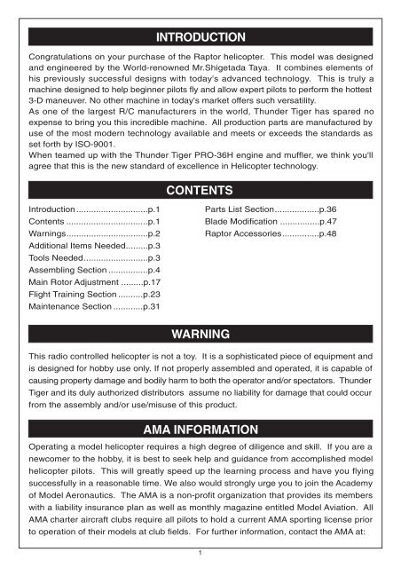
INTRODUCTIONCongratulations on your purchase of the <strong>Raptor</strong> helicopter. This model was designedand engineered by the World-renowned Mr.Shigetada Taya. It combines elements ofhis previously successful designs with today's advanced technology. This is truly amachine designed to help beginner pilots fly and allow expert pilots to perform the hottest3-D maneuver. No other machine in today's market offers such versatility.As one of the largest R/C manufacturers in the world, Thunder Tiger has spared noexpense to bring you this incredible machine. All production parts are manufactured byuse of the most modern technology available and meets or exceeds the standards asset forth by ISO-9001.When teamed up with the Thunder Tiger PRO-36H engine and muffler, we think you'llagree that this is the new standard of excellence in Helicopter technology.CONTENTSIntroduction.............................p.1Contents .................................p.1Warnings.................................p.2Additional Items Needed.........p.3Tools Needed..........................p.3Assembling Section ................p.4Main Rotor Adjustment .........p.17Flight Training Section ..........p.23Maintenance Section ............p.31Parts List Section..................p.36Blade Modification ................p.47<strong>Raptor</strong> Accessories...............p.48WARNINGThis radio controlled helicopter is not a toy. It is a sophisticated piece of equipment andis designed for hobby use only. If not properly assembled and operated, it is capable ofcausing property damage and bodily harm to both the operator and/or spectators. ThunderTiger and its duly authorized distributors assume no liability for damage that could occurfrom the assembly and/or use/misuse of this product.AMA INFORMATIONOperating a model helicopter requires a high degree of diligence and skill. If you are anewcomer to the hobby, it is best to seek help and guidance from accomplished modelhelicopter pilots. This will greatly speed up the learning process and have you flyingsuccessfully in a reasonable time. We also would strongly urge you to join the Academyof Model Aeronautics. The AMA is a non-profit organization that provides its memberswith a liability insurance plan as well as monthly magazine entitled Model Aviation. AllAMA charter aircraft clubs require all pilots to hold a current AMA sporting license priorto operation of their models at club fields. For further information, contact the AMA at:1
Academy of Model Aeronautics5151 East Memorial DriveMuncie, IN 47<strong>30</strong>2(317) 287-1256FLIGHT SAFETY CHECKLIST1. Make sure both the transmitter and receiver batteries are fully charged prior to operation thehelicopter.2. Make sure all flight controls operate properly prior to flying.3. Range check the radio before the first flight. The servos must operate properly with thetransmitter antenna collapsed at a range of at least 50 ft.(15 meters).4. Check to make sure there is no radio interference on your radio channel before operatingthe helicopter.5. Use only the recommended engine fuel as specified by the engine manufacturer.6. Make sure the transmitter and receiver are turned on before starting the engine.7. The engine throttle must be in the idle position before starting the engine.8. Model helicopter main and tail rotors operate at high RPM. Make sure nothing can come incontact with the rotor blades during flight.9. After starting the helicopter, maintain a safe distance during the flight.10. Never operate the helicopter in rain or excessive wind conditions.11. Always operate and fly your helicopter in a safe and responsible manner.12. Never fly a model helicopter over other pilots, spectators or cars.POST FLIGHT INSPECTION1. Inspect the model thoroughly to insure no parts have come loose or become damaged duringthe flight and landing. Replace damaged parts and tighten loose screws before flying again.2. Pump out any remaining fuel from the fuel tank.3. Wipe off excess oil and fuel from helicopter body and other exposed parts.4. Lubricate all moving parts ensure smooth operation for the next time you fly.5. Store model in a cool, dry place. Avoid storage in direct sunlight or near a source of heat.Following these few, simple safety rules will allow you to enjoy the thrill of model helicopter flyingfor many years to come.2
RADIO SETOTHER ITEMS REQUIREDReceiverBattery1000mAhSwitch harnessTransmitter(helicopter type only6 or more channels)Servo x 5GyroENGINEGlow Fuel(15%-<strong>30</strong>%)12V Electric starterGlow PlugExtended 6mm HexHELI ENGINE(<strong>30</strong>-size)Fuel PumpStarting Tool12V Battery1.5V Glow starter(1.2V~1.5V)FoamRubber BandTraining GearRemote Glow PlugExtension(for beginners only)Screw DriverGlow Plug WrenchTOOLS REQUIRED FOR ASSEMBLYNeedle Nose Pliers 5.5mm Wrench Ball Link Pliers Nipper Scissors7mmMetric4-way Wrench5.5mm7mm8mmHobby KnifeInstant GlueBlue LocktiteGreaseEpoxyHex Wrench5.5mm7mm8mm10mmSocket Drivers3
ASSEMBLING SECTIONThe parts in the <strong>Raptor</strong> kit are packed according to the assembly steps. The part number and quantity containedin each are always shown in the square box on each page. Do not open all the bags at once. Open only openthe bag that is needed for the current assembly step.4
Fuel Tank Ass'y1 Fuel Tank AssemblyNote: After assembly, check to make sure the Fuel Tankclunk can move from top to bottom without touching theback of tank. Also, a fuel filter (available from any hobbyshop, TTR1164) should be placed between the fuel tankand the carburetor.To Engine(3 )BK0063(2 )BK0062(6) BB362-2(5 )CB0363(6) BB362-2(4 )BE1867To Muffler(1) BK0061 Fuel Tank .....................1(2 )BK0062 Fuel Tank Grommet......1(3 )BK0063 Fuel Tank Nipple ..........1(4 )BE1867 Clunk.............................1(5 )CB0363 Silicone Fuel Tube........1(6 )BB0362-2 Silicone Fuel Tube.....2(1) BK00612 Clutch Bell Assembly(1) HM<strong>V1</strong>680(1) HM<strong>V1</strong>680 Bearing (d8xD16xW5).....1(2) HM<strong>V1</strong>150X Bearing (d5xD11xW5)...1(3) BK0039 Clutch Bell..........................1(4) BK0043 Drive Gear(Pinion).............1(5) BK0041 Clutch Liner........................1(4) BK0043(3) BK0039(2) HM<strong>V1</strong>150X(5) BK0041Glue the Clutch Bell Liner to theinside of the clutch Bell using athin coat of 5-minute epoxy.5
3 Main Frame Assembly-Part1If necessary, use a drop of CA on the screws to hold them securely in place. Tighten the screws snugly, but do notover torque them which could strip the plastic.Insert starter Shaft through the center of the clutch bell assembly, through the top starter shaft bearing and into thestarter coupling. Secure with the two set screws. Make sure this is very tightly secured.(1) HSE3-12B Self Tapping Screw (M3x12)..<strong>30</strong>(2) HM<strong>V1</strong>650 Bearing (d5xD16xW5).............1(3) HMV6800 Bearing (d10xD19xW5).......... 2(4) BK0059 Frame Spaeer (S).......................8(5) BK0058 Frame Spaeer (L)...................... 4(6) HME4-5B Set Screw (M4x5)................... 2(7) BK0081 Pin............................................. 2(8) BK0057 Servo Frame.............................. 1(9) BK0055 Main Frame Left Side.............. 1(10) BK0056 Main Frame Right Side.......... 1(11) BV0035 Guide Pulley.......................... 2(12) BK0036 Pulley Collar.......................... 4(13) BK0044 Starter Shaft.......................... 1(14) BK0045 Starter Coupling.................... 1(15) Fuel Tank Assembly(16) Clutch Assembly(10) BK0056(14) BK0045(6) HME4-5B(3) HMV6800 Upper Main Shaft bearing(4) BK0059 Main Frame Spacer(S)(5) BK0058 Main Frame Spacer (L)(1) HSE3-12B(7) BK0081(12) BK0036(2) HM<strong>V1</strong>650Top Starter ShaftBearing(11) BV0035(1) HSE3-12B(8) BK0057(9) BK0055(1) HSE3-12B(16) Clutch Bell Assembly(13) BK0044(15) Fuel Tank Ass'y(3) HMV6800Lower Main Shaft Bearing6
4 Main Drive Gear Assembly(2) HMQ14(1) HMC3-12B Socket Screw (M3x12).......... 4(2) HMQ14 Snap Ring.................................... 2(3) BV0033 One Way Clutch Housing.............1(4) BK0031 Main Spur Gear........................... 1(5) BK0032 Tail Drive Pulley........................... 1(6) BK0034 One Way Clutch Shaft..................1(2) HMQ14(3) BV0033(4) BK0031(5) BK0032Add a drop of Blue Locktite on thethread of each of these four screws.(1) HMC3-12B(2) HMQ14(6) BK00345 Washout Assembly(1) HMJ2-10N Self Tapping Screw(M2x10).. 2(2) HMC3-10B Socket Screw (M3x10)......... 2(3) HMV740ZZ Bearing (d4xD7xW2.5)........ 4(4) BK0077 Collar ........................................ 2(5) BK0079 Pin............................................. 2(6) BK0075 Linkage Ball.............................. 2(7) BK0015 Plybar Control Lever.................. 2(8) BK0016 Washout Linkage ..................... 2(9) BK0014 Washout Base............................1Make sure Linkage Balls are attached to theinside hole of each stabilizer control lever.(6) BK0075(2) HMC3-10B(4) BK0077(3) HMV740ZZ(7) BK0015(5) BK0079(1) HMJ2-10N(3) HMV740ZZ(8) BK0016(3) HMV740ZZ(9) BK0014(5) BK0079(2) HMC3-10B(4) BK0077(3) HMV740ZZ(1) HMJ2-10N(6) BK0075(7) BK0015(8) BK0016For model numders 4831/4832, (3) will be replaced by Bushing(BK0107x4)7
6 Main Frame Assembly-Part2Add a drop of CA to the two screws at the pivoting point of the collective pitch control arm.Attach the linkage rod to the parallel elevator linkage balls.(1) HSE3-18B Self Tapping Screw(M3x18)....4(2) HSE3-12B Self Tapping Screw(M3x12)... 1(3) HMJ3-22B Self Tapping Screw(M3x22)....1(4) HMJ2-14N Self Tapping Screw(M2x14)... 1(5) HMJ2-10N Self Tapping Screw(M2x10)... 6(6) HM<strong>V1</strong>280 Bearing (d8xD12xW3.5)......... 2(7) HMV740ZZ Bearing (d4xD7xW2.5)........ 6(8) HMV840ZZ Bearing (d4xD8xW3)............ 2(9) BK0076 Collar......................................... 3(10) BK0078 Collar ...................................... 2(11) BK0088 Flat Washer ......................... 1(12) BK0084 Pin .......................................... 2(13) BK0075 Linkage Ball..............................8(14) BK0023 Elevator Control Arm Link........ 2(15) BK0018 Elevator Control Arm................ 1(16) BK0020 Elevator Arm Control Shaft.......1(17) BK0022 Aileron Control Lever................2(18) BK0019 Elevator Arm Parallel Lever......1(19) BK0086 Ball Link....................................2(20) BK0093 Linkage Rod ............................ 1(21) BK0021 Elevator Control Lever..............1(22) BK0017 Collective Pitch Control Arm.....1For model numbers 4831/4832,(7) will be replaced by Bushing(BK0107x6)(8) will be replaced by Bushing(BK0108x2)(14) BK0023(15) BK0018(14) BK0023(12) BK0084(6) HM<strong>V1</strong>280(18) BK0019(21) BK0021(13) BK0075(1) HSE3-18B(5) HMJ2-10N(7) HMV740ZZ(5) HMJ2-10N(13) BK0075(7) HMV740ZZ(9) BK0076(6) HM<strong>V1</strong>280(16) BK0020(1) HSE3-18B(5) HMJ2-10N(13) BK0075(1) HSE3-18B(9) BK0076(7) HMV740ZZ(17) BK0022(7) HMV740ZZ(2) HSE3-12B(10) BK0078(8) HMV840ZZAdd CA tothis screw(5) HMJ2-10N(13) BK0075(1) HSE3-18BAdd CA to this screw(19) BK0086(20) BK0093(22) BK0017(8) HMV840ZZ(10) BK0078(11) BK0088(7) HMV740ZZ66mm(3) HMJ3-22B(4) HMJ2-14N(9) BK0076(7) HMV740ZZ(13) BK0075Warning, do not over-torque the self-tapping screws.8
7 Main Frame Assembly-Part3Insert Main Shaft through the shaft bearings making sure that the end with the holes closest to the end ispointed down. Next, slide main gear assembly into position on the shaft and line up the holes in the mainshaft with the holes in one way clutch shaft of the main gear assembly. Insert the socket head screw andsecure with the lock nut. Next, slide on the mainshaft lock ring on top of the main shaft bearing and securewith the two set screws. Then slide on the swash plate assembly and attach the elevator and aileroncontrol linkages to the outside swash plate linkage balls. Next, slide on washout assembly and attachwashout linkage to the inner linkage balls of the swash plate.(1) HMC3-20B Socket Screw(M3x20).......1(2) HMM3Z Lock Nut (M3)........................ 1(3) HME4-5B Set Screw (M4x5)............... 2(4) BK0086 Ball Link ................................ 4(5) BK0092 Linkage Rod ......................... 2(6) BK00<strong>30</strong> Main Shaft Lock Ring............ 1(7) BK0029 Main Shaft ............................ 1(8) Wash Out Assembly(9) BV0013 Swash Plate Assembly...........1(10) Main Gear Assembly(4) BK0086(5) BK0092(7) BK0029(8) Washout Assembly(9) BV0013(3) HME4-5B(4) BK0086(5) BK0092(4) BK0086(6) BK00<strong>30</strong>55mm(1) HMC3-20B (2) HMM3Z8 Landing Skid Assembly(10) Main Gear Assembly(1) HSE3-18B Self Tapping Screw(M3x18).4(2) HME4-5B Set Screw(M4x5)..................4(3) BK0066 Skid Brace...............................2(4) BK0064 Skid Pipe.................................2(5) BK0065 Skid Pipe End Cap..................4(2) HME4-5B(3) BK0066(2) HME4-5B(3) BK0066(2) HME4-5B(4) BK0064(5) BK0065 (1) HSE3-18B(5) BK00659
9 Engine AssemblyNote: A piston lock purchased from your dealer will make this amuch easier task. You must replace the standard throttle armw/the extended throttle arm and attach the linkage ball.(1) HMC3-10B Socket Screw(M3x10)..... 2(2) BK0040 Clutch Shoe..........................1(3) BV0038 Cooling Fan..........................1(4) No.9670 TT PRO-36H Engine............1(1) HMC3-10B(2) BK0040(1) HMC3-10BTighten the engine nut securely bygrabbing the plastic fan with a towel.Linkage Ball tothrottle Arm(3) BV0038Add Blue Locktite(4) No.967010 Main Frame Assembly-Part4Add blue loctite to all metal to metal screw surfaces. After installingthe engine, connect the silicone fuel tube to the carburator and muffler.(1) HMC3-14B Socket Screw(M3xH)....... 8(2) HMC3-32B Socket Screw(M3x32)..... 2(3) BK0087 Flat Washer........................ 4(4) BK0037 Engine Mount........................ 1(5) No.9267 Muffler................................... 1(6) Engine AssemblyAdd Blue Locktite(1) HMC3-14B(5) No.9267(3) BK0087(2) HMC3-32B(1) HMC3-14BAdd Blue Locktite(3) BK0087(6) Engine Ass'y.(3) BK0087(1) HMC3-14B(4) BK0037(1) HMC3-14BEngine mountAttachment10
11 Main Rotor Head AssemblyAssembly Hint: Start from the bottom of the main Rotor Hub and work your way up to the flybar assembly. Whenscrewing on the flybar paddles to the flybar, stop when you can see the rod in the window of the paddle. Then, laythe assembly on a flat surface and align the paddles so they are exactly parallel. Insert and tighten the set screws.Attach the flybar control rod to the flybar control arm and use the Double Link to connect the mixing lever (shortside) to the Main rotor Pitch Housing.(1) HMC3-14B Socket Screw(M3x14)........... 2(2) HMC3-8B Socket Screw(M3x8)................2(3) HMJ2-10N Self Tapping Screw(M2x10)....8(4) HME4-5B Set Screw(M4x5)......................2(5) HME3-10B Set Screw(M3x10)..................2(6) HSE3-5B Self Tapping Screw(M3x5)........4(7) HMM4Z Lock Nut(M4).............................. 2(8) HMV8<strong>30</strong>ZZ Bearing (d3xD8xW4)............ 2(9) HMV740ZZ Bearing (d4xD7xW2.5)......... 4(10) HMV840ZZ Bearing (d4xD8xW3).......... 2(11) HM<strong>V1</strong>350 Bearing (d5xD13xW4)........... 4For 4831/4832,(9) will be replaced by Bushing(BK0107x4)(8) will be replaced by Bushing(BK0108x2)(4) HME4-5B(19) BK0002(31) BK0075(3) HMJ2-10N(31) BK0075(22) BK0006(9) HMV740ZZ(13) BK0076(1) HMC3-14B(31) BK0075(9) HMV740ZZ(3) HMJ2-10N(16) BK0088(23) BK0001(11) HM<strong>V1</strong>350(32) BK0008(6)(7)(11)(12)(5) HME3-10B(17) BK0067(18) BK0010(<strong>30</strong>) BK0003(26) BV0085(25) BK0007(15) BK0096(25) BK0007(27) BK0011(29) BK0097 (28) BK0012(32) BK0008(12) HMX0510 Thrust Bearing (d5xD10xW4)..2(13) BK0076 Collar.......................................... 2(14) BK0078 Collar.......................................... 2(15) BK0096 Flap Collar.................................. 2(16) BK0088 Flat Washer................................ 2(17) BK0067 Flybar Paddle............................ 2(18) BK0010 Flybar Rod..................................1(19) BK0002 Flybar Control Arm.................... 2(20) BK0005 Flybar Arm Bushing................... 2(21) BK0004 Flybar Seesaw Hub.................... 1(22) BK0006 Mixing Lever.............................. 211(17) BK0067(24) BK0009Small Internal Diameteralwaysgo toward the bladeLarge Internal Diameteralwaysgo next to the thrustcollarDiagram for Thrust Bearing Assembly(23) BK0001 Main Rotor Pitch Housing...........(24) BK0009 Feathering Shaft................(25) BK0007 Flybar Control Rod.............(26) BV0085 Double Link ......................(27) BK0011 Flap Damper......................(28) BK0012 Pin.....................................(29) BK0097 Main Rotor Hub Pin............(<strong>30</strong>) BK0003 Main Rotor Hub..................(31) BK0075 Ball Link.............................(32) BK0008 Thrust Collar......................(5) HME3-10B(20) BK0005(8) HMV8<strong>30</strong>ZZ(21) BK0004(3) HMJ2-10N(31) BK0075(9) HMV740ZZ(13) BK0076(22) BK0006(10) HMV840ZZ(14) BK0078(2) HMC3-8B(26) BV0085(11) HM<strong>V1</strong>350(32) BK0008(3) HMJ2-10N(31) BK0075(23) BK0001(6) HSE3-5B(12) HMX0510(11) HM<strong>V1</strong>350(7) HMM4Z
12 Main Frame Assembly-Part5Slide the main Rotor assembly over the main shaft and align the two pins toslide in the washout assembly. Make sure the holes in the main shaft lineup with the holes in the main rotor head. Insert the socket screw and securewith locknut. Attach the ball linkage rods to the long end of the mixing leverand to the remaining inside linkage balls of the swash plate.(1) HMC3-20B(1) HMC3-20B Socket Screw(M3x20)..... 1(2) HMM3Z Lock Nut(M3)........................1(3) HME3-18B Set Screw(M3x18)........... 1(4) BK0095 Linkage Rod......................... 2(5) BK0086 Ball Link............................... 4(6) BK0103 Canopy Retaining Post........ 2(7) Main Rotor Head Assembly(7) Main Rotor Head Ass'y.(5) BK0086(4) BK0095(2) HMM3Z(6) BK0103(3) HME3-18B(5) BK0086(5) BK0086(4) BK0095(5) BK0086(3) HME3-18B(6) BK010313 Tail Unit AssemblyAssembly Tip: Work from left to right when assembling the parts. The tail pitchcontrol lever screws into the arm extending from the tail unit housing.(1) HSE3-18B Self Tapping Screw(M3x18).1(2) HMJ2-10N Self Tapping Screw(M2x10) 4(3) HSE2-10B Self Tapping Screw(M2x10).2(4) HMF2-8N Screw(M2x8).........................2(5) HME3-18B Set Screw(M3x18).............. 2(6) HMM3Z Lock Nut(M3)........................... 2(7) HM<strong>V1</strong>150X Bearing (d5xD11xW5)....... 1(8) HMV8<strong>30</strong>ZZ Bearing (d3xD8xW4)........ 4(9) HM<strong>V1</strong>060 Bearing (d6xD10xW3)........ 2(10) HMV740ZZ Bearing (d4xD7xW2.5)... 2(11) BK0082 Collar(2x3x4)......................... 2(12) BK0076 Collar(3x4x10)....................... 1(13) BK0083 Pin(2x9)................................. 2(14) HMU2-12B Spring Pin(2x12)...............1(15) BK0088 Flat Washer............................1(16) BK0048 Tail Pitch Housing (A)........... 2(17) BK0049 Tail Pitch Housing (B)........... 2(18) BK0054 Tail Rotor Hub....................... 1(19) BK0026 Tail Pitch Control Link........... 2(20) BK0025Tail Pitch Control Fork............ 1For 4831/4832, (10) will be replacedby Bushing(BK0107x2)(21) BK0027 Tail Pitch Control Slider.................. 1(22) BK0028 Tail Pitch Control Slide Bushing..... 1(23) BK0053 Tail Rotor Shaft.............................. 1(24) BK0050 Tail Pulley....................................... 1(25) BK0051 Tail Pulley Flange...........................1(26) BK0024 Tail Pitch Control Lever.................. 1(27) BK0047 Tail Unit Housing (R)...................... 1(28) BK0075 Link Ball......................................... 2(22) BK0028(23) BK0053(6) HMM3Z(5) HME3-18B(8) HMV8<strong>30</strong>ZZ(17) BK0049(3) HSE2-10B(11) BK0082(19) BK0026(20) BK0025(9) HM<strong>V1</strong>060(16) BK0048(2) HMJ2-10N(18) BK0054(2) HMJ2-10N(5) HME3-18B(13) BK0083 (6) HMM3Z(21) BK0027(17) BK0049(28) BK0075 (4) HMF2-8N (8) HMV8<strong>30</strong>ZZ(27) BK0047(7) HM<strong>V1</strong>150X(14) HMU2-12B(24) BK0050(25) BK0051(10) HMV740Z(28) BK0075(4) HMF2-8N(15) BK0088(26) BK0024(12) BK0076(1) HSE3-18B(16) BK004812
14 Tail Boom AssemblyAssembly Tip: Slide the 3 rod guides onto the boom and space them out evenly as shown. Then slide the tail linkagerod into the rod guides. Next, insert the tail rotor drive belt into the boom so that it comes out of both ends. Placedrive belt over tail drive pulley and complete balance of tail boom assembly. Remember to connect the tail linkagerod to the tail control lever.(17) Tail Unit(1) HMC3-20B Socket Screw(M3x20)..4(2) HMC3-25B Socket Screw(M3x25)..2(1) HMC3-20B(16) BV0052(3) HSE3-12B Self Tapping Screw(M3x12).. 4(4) HMM3Z Lock Nut(M3).................... 6(2) HMC3-25B(5) HM<strong>V1</strong>150X Bearing (d5xD11xW5)..1(6) BK0046 Tail Unit Housing (L)..........1(5) HM<strong>V1</strong>150X(6) BK0046(7) BK0071 Vertical Fin........................ 1 (15) BK0086(8) BK0069 Stabilizer Fin..................... 1 (8) BK0069(9) BK0070 Stabilizer Fin Bracket........ 1(14) BK0100-2(10) BK0090 Tail Boom Support.......... 2(11) BK0060 Tail Boom........................ 1(12) BK0091 Rod Guide........................3(12) BK0091(13) BK0089 Tail Rotor Drive Belt... .....1(14) BK0100-2 Tail Linkage Rod.......... 1(15) BK0086 Ball Link.......................... 1(16) BV0052 Tail Idle Pulley................. 1(17) Tail Unit(12) BK0091(11) BK0060(12) BK0091(4) HMM3Z(7) BK0071(13) BK0089(10) BK0090(9) BK0070(3) HSE3-12B15 Main Frame Assembly-Part6(5) BK0068(4) HMM3Z(1) HMC3-14B Socket Screw(M3x14)......2(2) HMC3-20B Socket Screw(M3x20)......4(3) HSE3-12B Self Tapping Screw(M3x12)....2(4) HMM3Z Lock Nut(M3)........................ 6(5) BK0068 Tail Rotor Blade.................... 2(6)Tail Assembly(6)Tail Ass'y(4) HMM3Z(1) HMC3-14B(5) BK0068(2) HMC3-20BInsert the four 3x20 socket screws into the tail base of the Main Frameand secure with lock nuts. Do not tighten at this point.Hold the tail boom in one hand and hook your index finger on your freehand through the exposed loop of the tail rotor drive belt. Hold it so thebelt is vertical and parallel to the tail drive pulley.Boom Drive beltImportant: Next, rotate the belt 90-degree counter clockwise.90-degreePull the belt through the tail base, keeping the belt correctly aligned.Push the tail boom into the tail base all the way to the end. Place thedrive belt over the tail drive spur gear. Then, gently pull back on the tailboom until the tension on the belt allows no more than 5mm(3/16") offree play in the belt. Tighten the locknuts and proceed with the rest ofthe assembly.(3) HSE3-12B(4) HMM3Z13
16 Servo Installation-Part1Assembly Tip: Remove all the servo wheels prior to attaching the steel linkageballs. Make sure all linkages are the correct length.(1) HSE2612N Self Tapping Screw(M2.6x12)....12(2) HMF2-8N Screw(M2x8)................................. 4(3) HML2 Hex Nut(M2)....................................... 4(4) HME4-5B Set Screw(M4x5).......................... 2(5) BK0093 Linkage Rod.................................... 2(6) BK0094 Linkage Rod..................................... 1(7) BK0100-1 Linkage Rod................................. 1(8) BK0105 Tail Control Rod Joint....................... 1(9) BK0075 Linkage Ball..................................... 4(10) BK0086 Ball Link......................................... 7Before installing Aileron Servo, tape thewire as shown.FUTABA72mmMount the Steel Linkage Balls at 10.5mm(approx 7/16") from the center of the servohorn.(1) HSE2612N(9) BK0086(5) BK0093(2) HMF2-8N(9) BK0075(3) HML2(1) HSE2612NAileron Servo(4) HME4-5BElevator Servo(8) BK0105(7) BK0100-1(10) BK0086(1) HSE2612NRudder Servo(6) BK009484mm(10) BK0086(1) HSE2612N(1) HSE2612N(9) BK0075(2) HMF2-8N14
17 Servo Installation-Part2Assembly Tip: Remove all the servo wheels prior to attaching the steel linkageballs. Make sure all linkages are the correct length.(1) HSE2612N Self Tapping Screw(M2.6x12).... 8(2) HMF2-8N Screw(M2x8)................................ 3(3) HML2 Hex Nut(M2)...................................... 3(4) BK0075 Linkage Ball.................................... 3(5) BK0094 Linkage Rod .................................. 1(6) BK0092 Linkage Rod .................................. 1(7) BK0086 Ball Link.......................................... 4Mount the Steel LinkBall at 10.5mm(approx7/16") from the centerof the servo horn.Pitch Servo53mm(7) BK0086(6) BK0092(3) HML2(4) BK0075(1) HSE2612N(2) HMF2-8N(3) HML2(4) BK0075(2) HMF2-8NThrottle Servo(1) HSE2612N(3) HML2(4) BK0075(2) HMF2-8N(7) BK0086(5) BK0094(1) HSE2612N77mm18 Main Rotor AssemblyImportant-While Thunder Tiger takes great care to manufacture the most balanced blades available, no two rotorblades are exactly the same. It is highly recommended that you purchase a blade balancer from your hobby dealer.Follow the manufacturers instructions for balancing the blades and install on helicopter.(1) BV0072 Main Rotor Blade.................2(2) HMM4Z Lock Nut(M4)...................... 2(3) HMC4-27B Socket Screw..................2(3) HMC4-27B(1) BV0072(2) HMM4Z•See page47 forblade modification.15
Setting up Main Rotor Blades Pitch Angle•On the left side frame, there arethree pitch scales molded ontothe plastic frame. The threedifferent scales are designed forbeginner, intermediate or expertF3C and 3D pilots.•Use the "pointer" on the collectivetray and the plastic molded scalesto set up the initial collectivecontrol.•The actual blade angle in degreescan be checked using a pitchgauge (sold seperately).For BeginnersFor IntermediatesFor F3C or 3DTop End Pitch 12˚Hover 6˚Beginners 0˚Intermediates -4˚PointerBottem End Pitch -8˚(Hint for beginners)The hoveing pitch angle should be at 6˚. To get the 0˚ to 12˚collective range, mount the steel linkage ball at 10.5mm awayfrom the center of the collective servo horn.FUTABAMount the SteelLinkage Ball at10.5mm from thecenter of the servohorn.Throttle Stick in the centerposition6˚ hovering pitch angle is used for beginners, intermediates and experts. The throttle/collective must bein the center position when adjusting the collective pushrod length to make the "point" line up with the 6˚hover point on the molded scale(see above diagrams).17
•High End Blade Pitch SettingLinkage Position for beginnerThrottle at High Position•Move the throttle/collective stick to the full throttle position(see upper right diagram). The molded "pointer"should now line up with the upper limit mark, which should provide about 12˚ of blade pitch.•Low End Blade Pitch SettingThrottle at Low Position•Move the throttle/collective stick to the low stick position. Use the ATV function of your transmitter tomake the "pointer" line up with the 0˚ mark for beginners(with the -4˚ mark for intermediates, and -8-degree mark for experts).18
Collective Travel for F3C and 3D Flying•To achieve +12˚ to -8˚ of collective travel range, the steel linkage ball must be moved to the innerlocation as shown in the figure.•Use ATV function of the transmittler to get the necesary servo travel.•High End Blade Pitch SettingLinkage Position for F3C or 3DThrottle at High PositionThe molded "pointer" should line up with the upper limit mark, whichshould provide about 12˚ of blade pitch.•Low End Blade Pitch SettingPosition for F3C or 3DThrottle at Low PositionFor intermediates set the low end to -4˚. For advanced F3C and 3D flying,set the low end to -8˚.19
Engine Throttle Control LinkageMount the steel linkage ball to the outer hole on the metal throttle arm. At full throttle stick, thecarburetor hole should open completely. At low throttle and with the throttle trim all the way down,the carburetor hole should close completely. Adjust the ATV function in your transmitter to achievethe above requirement. Listen to the servo, it should not make any binding noise. Try keep thethrottle ATV between 90% and 110%. If your radio does not have ATV, then adjust the locationof the steel link ball on the throttle servo horn to get the correct throttle travel.20
FLIGHT TRAINING SECTION21
Preflight AdjustmentsRelationship between the control motion and radio transmitter.Always check all the controls to make sure they movein the correct direction and there is no mechanicalbinding or noise from the servos.22
Preflight Checklist and Starting Procedure(1) Check to make sure there is no radio interfence before operating the model helicopter.(2) Make sure the transmitter and receiver are on and all controls operate properly before flight.Range check the radio.(3) The engine carburetor must be in the idle position before starting the engine. Please readthe engine instruction <strong>manual</strong> on how to properly adjust the engine. Set the carburetor mainneedle according to the engine instruction. Depending on the fuel and glow plug used, thecarburetor idle screw may require fine adjustment of 1/4 to 1/2 turn away from the factorysetting.(4) Fill the fuel tank, move the throttle stick to idle, and connect the glow plug battery to the glowplug.(5) Use a 12 volt electric starter along witha 6 mm hex starter extension (soldseperately) to start the engine.•Always grab on the helicoptermain rotor head whenstarting the engine.Otherwise, the main rotormay start spinningimmediately after theengine is started.23
Flying Adjustments (1)Tracking adjustment ... When the two main rotor blades are in track it means their blade tipsshould follow the same path as they rotate.(1) Rev up the motor until the helicopter becomeslight on its skids. Stand about 15 feet(4 meters)alway from the helicopter.(2) When the two main rotor blades are intrack it means the blade tips should followthe same path as they rotate.increasethrottle gentlyand not toomuch(3) When both blades are in track, the bladetips will appear to overlap as seen fromthe edge of the rotor plane.out of trackIf the blades are out of track, then adjustone of the pushrods that connects to themain rotor blade pitch arm.Redo steps (1) to (3) untilthe blades are trackingproperly.in trackIn hover, the main blades should bearound 5.5 to 6 degrees in pitch.24
Flying Adjustments (2)Trimming: All helicopters are inherently unstable. But when a helicopter is properly trimmed, itwill not drift away or yaw by itself quickly. Use the following procedure to trim yourhelicopter.(1) If the helicopter nose starts to yaw left or right,then use the transmitter trim to compensate:yaw rightyaw left(A) situation: move to (b)(B) situation: move to (a)(2) If the helicopter rolls to left or right, then:rolls rightrolls left(C) situation: move to (d)(d) situation: move to (c)(3) If the helicopter noses down or up, then:Noses downNoses up(E) situation: move to (f)(F) situation: move to (e)25
Hover Training (1)Hovering is when the helicopter is floating in a stationary position in the air. Hovering is thefundamental manuever to learn first. Here is the procedure to practice hovering:(1) Make sure there are no spectators anywherenear the model helicopter. You, the pilot,should stand at least 10 meters (<strong>30</strong> feet)behind and slightly to the side of the modelhelicopter.(2) Prior to lifting off, while the main rotor is spinning and the helicopter ison the ground, check the main rotor fore/aft and left/right cyclic to makesure the main rotor is tilting in the correct direction according to yourcyclic command. Move the tail rotor control stick to make sure thehelicopter nose will swing in the desired direction.(3) Increase the throttle/collective to lift the model helicopter skids off theground to no more than 10 cm(4 inches). Initially, it will be very difficultto control the model to prevent it from moving. For a beginner it willalso be difficult to determine whether the helicopter is in trim or not.But with repeated practice close to the ground you will develop a feelfor the controls. It is recommended to let a more experienced modelhelicopter pilot trim out your new model before you attempt to learnto hover.26
Hover Training (2)(1) It will take a few hours of hover practice with the helicopter skids at 10 to 20 cm (4-8 inches)off the ground in order to comfortably control the model.Do not try to lift the model to more than 10 to 20 cm(4-8 inches) in the beginning becausethen the model may tip over readily when the beginner panics and an incorrect command isgiven. Once you can keep the model in one place, then it is time to slowly increase the heightby a few centimeters (inches) each flight. Soon, you will be able to hover the helicopterconfidently a few feet high. Beginners should always practice hovering close to the groundbecause in an emergency, throttle and collective can be reduced rapidly without causing alarge drop or damage to the model. If the model is hovering beyond one meter(3 feet) altitude,always descend slowly. A panic drop can damage the helicopter.(2) Always stand behind the model helicopter when learning how to hover. Then you can watchthe nose of the helicopter. A left tail rotor command will yaw the helicopter nose to the left,and a right command will yaw to the right. Similarly, a left cyclic command will cause thehelicopter to translate left. After you can comfortably hover the model at one meter highwithout drifting, then start practice hovering while standing to either side of the model.Eventually, you need to be comfortable at hoveringthe model from any orientation, including withthe helicopter nose pointing at you. This ischallenging because control directions arereversed.(3) Once you can confidently hover a model helicopter at any altitude and at any orientation,then congratulate yourself because you have mastered 80% of the fundamental controlmovements of a helicopter.27
Forward Flight TrainingAfter mastering hovering flight:(1) Start practicing moving the helicopter laterally to the left or right slowly from a 1.5 meter (60inches) high hover. This is the beginning exercise of translational flight.hovering at 1-1.5 meter(2) After a few hours of practicing step (1) and you are comfortable with translational movement,start using some tail rotor control so the helicopter nose will point slightly to the left or right asyou fly it to the left or right. Eventually, this pattern will become a figure-eight in front of you.Please visualizethese movements in your mind.28
MAINTENANCE SECTION29
After Flight Checklist(1) Check every screw and bolt to make sure none has loosened due to vibration.(2) Check every rotating and movable part to ensure they still move smoothly and normally.(3) Clean off the exhaust residue from the muffler, engine, and helicopter.(4) Check all movable parts, such as gears, ball links, belt, etc. for unusual wear.Trouble Shooting[1]The engine will not start.* The engine starting shaft will not turn:The engine may be flooded with too much fuel. Please remove the glow plug first, then turn the enginewith the electric starter until the excess fuel spits out of the glow plug hole.* The engine turns when the electric starter is applied, but the engine will not start:(1) Is the glow plug working? Remove the glow plug and does the platinum coil glow red when a 1.5volt battery is applied to the plug? If not, then the glow plug battery may be weak and old.(2) Is the carburetor needle properly set? Please refer to the engine instruction <strong>manual</strong> for the properneedle setting.(3) Does the throttle control arm move properly and in the correct direction according your transmittercommand?* Engine will start, but quits immediately.(1) Use the transmitter to increase the carburetor opening slightly. The throttle stick should never exceedthe 1/3 positiom when starting the engine.(2) Try a new or different type of glow plug. There are different types of glow plugs on the market fordifferent types of fuel and operating conditions. Seek the advice of experienced fliers and alsoexperiment with different types of glow plugs until you find the one that suits your operating conditionthe best.*Engine runs, but the helicopter will not lift off.(1) Check the main rotor blade pitch angle, they should be set at 5.5 to 6 degrees when the transmitterthrottle/collective stick is at the center position.(2) Does the engine throttle arm move properly? The carburetor opening should be fully open whenthe transmitter throttle/collective stick is moved up. The carburetor opening should be nearly closedwhen the transmitter throttle/collective stick is moved down. And the opening should be completelyclosed when the transmitter throttle/collective stick is moved down and the throttle trim is alsomoved down.(3) The carburetor needle is not set properly. Close the needle (turn it clockwise) all the way, thenopen the needle (turn it counter clockwise) 1 and 1/2 turns and try again. If the model still will notlift, then the engine maybe running too rich. If the symptom is the engine exhaust has a lot ofsmoke and the engine coughs and wants to quit when the transmitter throttle/collective stick ismoved up, then close the needle 1/8 turn at a time, until the model will lift off. Do not turn theneedle too far inward, that will make the engine run too lean and over-heat and damage the engine.[2] Helicopter problems.* The helicopter shakes.(1) Is the blade spindle bent?(2) Is the flybar bent?(3) Is the main rotor shaft bent?(4) Are the two control paddles mounted at the same distance from the rotor shaft, and the paddlesare parallel to each other, and in the proper direction?(5) Is the tail rotor shaft bent? The tail rotor blades mounted properly or damaged?(6) Are the main rotor blades damaged or mounted in the proper orientation? The blades may requireadditional balancing. The blade balance can be checked by removing both blades and then useone of the 4mm blade bolt and nut to hold the two blades together like a teeter totter. Then, holdthe blade bolt with your thumb and index finger. The two blades should teeter and remain in alevel position. If not, then add some tape to the lighter blade near the blade tip until the two bladesteeter in a level position. Hobby shops also sell blade balancers that are designed solely forbalancing model helicopter blades.<strong>30</strong>
In the event the model has crashed.Inspect the flybar, rotor shaft and the blade spindle to make sure they are not bent at all. If any item isdamaged, it must be replaced with a new part to ensure safe operation. Do not glue any broken or damagedplastic part. Do not repair broken rotor blades. Always inspect the following items immediately:Engine starting shaft.All the gears.Main shaft, flybar and blade spindle.Tail boom and support.Vertical and horizontal fins.Tail rotor shaft and control system.Main and tail rotor blades.Changing the main rotor shaft:(1) Disconnect the control rods to the washout arms.(2) Disconnect the washout link to the swashplate.(3) Loosen the set screws on the collar.(4) Remove the 3mm x 20 bolt.(5) Hold on to the plastic main gear and pull the 10mmmain rotor shaft upward.(3)(2)(1)(1)(2)(3)(4)(1)(3)(2)Changing the blade feathering spindle:(1) Disconnect the linkage rods to the blade grips.(2) Remove the 7mm nuts.(3) Pull out the blade grips gently.31
Changing the tail drive belt:(1)Loosen and remove all the necessaryscrews.(2)After installing the new belt, make surethe belt is rotated 90˚ counter clockwise.(1)(1) (1)(1)(2)(1)Changing the flybar:(1) Loosen or remove the M3x10 set screws.(2) Unscrew the control paddles.* After reinstalling the flybar and paddles, makesure the paddles are level and flat.(2)(1)* Make sure the distance from the rotor shaft toboth paddles are the same.* If the flybar is not perfectly straight orsmooth, it can be lightly sanded.32
Changing tail rotor shaft:1. Remove the tail rotor gear box from the tail boom.2. Take apart the blade grips and remove or loosen theM3x18 set screws.3. Remove the tail rotor hub.4. Pull out the tail rotor shaft.5. Remove the plastic pulley by pushing out the1.8mmsteel pin. (2)(1)(3)(4)(5)33
ORDER BY BAG NUMBER ONLYINDIVIDUAL PARTS NOT AVAILABLEPV0001 Main Rotor Grip PV0002 Flybar Control Arm PV0003 Main Rotor Hub PV0004 Mixing LeverPV0005 Flybar Control Rod PV0006 Thrust Collar PV0007 Spindle PV0008 Flybar RodPV0009 Flap Damper PV0010 Swash Plate Assy. PV0011 Wash Out SetPV0013Elevator ArmPV0012Pitch Control ArmPV0014 Elevator Lever PV0015 Aileron LeverPV0016 Tail Pitch Control Lever PV0017 Tail Pitch Slider PV0018 Main Shaft Lock Ring PV0019 One Way Clutch341999.10 V.2
ORDER BY BAG NUMBER ONLYINDIVIDUAL PARTS NOT AVAILABLEPV0020 One Way Clutch Shaft PV0021 Guide Pulley Assy PV0022 Engine Mount PV0023 Clutch BellPV0024 Clutch PV0025 Starter Shaft PV0026 Starter Coupling PV0027 Tail CasePV0028 Tail Rotor Grip PV0029 Tail Pulley Set PV00<strong>30</strong> Tail Rotor Shaft PV0031 Tail Rotor HubPV0032 Main Frame Set PV0033 Servo Frame PV0034 Fuel TankPV0035 Landing Skid set PV0036 Flybar Paddle PV0037 Tail Rotor Blade1999.10 V.235
ORDER BY BAG NUMBER ONLYINDIVIDUAL PARTS NOT AVAILABLEPV0038Tail FinPV0039 Main Rotor BladesPV0040Double LinkPV0041 Ball Link PV0042 Tail SupportPV0043 Tail Control Rod PV0044 Linkage RodPV0046Elevator Arm Brg.PV0045BodyPV0047 Thrust Brg. PV0048 Pitch Frame/RotorHub Seesaw Brg.PV0049 Tail Grip &Seesaw Brg. PV0050 Feathering Brg. PV0051 Lever Brg. PV0052 Tail Slider Brg.361999.10 V.2
ORDER BY BAG NUMBER ONLYINDIVIDUAL PARTS NOT AVAILABLEPV0053 Rotor Bolt PV0054 Servo Mounting PlatePV0056 Frame Spacer(L) PV0057 Frame Spacer(S)PV0055DecalPV0058 Linkage Ball PV0059 Tail Shaft/Clutch Bell Brg. PV0061 Body Retaining Set PV0062 Body Mount RubberGrommetsAK0004 Flybar Seesaw AK0029 Main Shaft AK0031 Main Spur Gear AK0032 Tail Drive PulleyAK0043 Pinion Gear AK0089 Tail Drive Belt AV0038 Cooling Fan Assy.1999.10 V.237
AK0060Tail BoomAV0052Tail Idel Pulley Assy.PV0063 Pitch Frame/Rotor HubSeesaw Bushing(for 4831/4832)PV0064Lever Bushing(for 4831/4832)HMF2-6N M2X6HMF2-8N M2X8HMJ2-10N M2X10HMJ2-14N M2X14HMJ2-6B M2X6HMJ3-22B M3X22HMC3-10BHMC3-12BHMC3-14BHMC3-20BHMC3-25BHMC3-32BHMC3-8BM3X10M3X12M3X14M3X20M3X0.5L25M3X0.5XL32M3X8HSE2-10B M2X10HSE2612N M2.6X12HSE3-12B M3X12HSE3-18B M3X18HME3-10BHME3-18BHME3-5BM3X10M3X18M4X5HSE3-5B M3X5PV0090Clutch LinerPV0088 Screw Bag (6pcs each) PV0089 Screw Bag (6pcs each)NO.9267MufflerPV0065Canopy OnlyPV0066Body OnlyHNI15HNI2HNI25HNI3HNJ-1x3BK0109x2(2) (1)(16)(4)BK0106x2PV0060 Installation Set PV0093 Main Shaft Brg PV0091 Bearing Upgrade Kit38
ORDER BY BAG NUMBER ONLYINDIVIDUAL PARTS NOT AVAILABLENo. NAME Parts No. Parts Name quantity ReferenceAssemble StepPV0001 Main Rotor Grip BK0001 Main pitch Housing 2 11HSE3-5B M3x5 Selftapping Screw 4 11HMJ2-10N M2x10 Selftapping Screw 2 11BK0075 Linkage Ball 2 11PV0002 Flybar Arm BK0002 Flybar Control Arm 2 11BK0005 Flybar Arm Bushing 2 11HME4-5B M4x5 Set Screw 2 11HMJ2-10N M2x10 Selftaping Screw 2 11BK0075 Linkage Ball 2 11PV0003 Main Rotor Hub BV0003 Main Rotor Hub 1 11BK0097 Main Rotor Pin 1 11HMM3Z M3 Lock Nut 1 12HMC3-20B M3x20 Socket Screw 1 12PV0004 Mixing Lever BK0006 Mixing Lever 2 11BK0076 Collar (d3xD4xL10) 2 11BK0075 Linkage Ball 4 11BK0088 Flat Washer 2 11HMJ2-10N M2x10 Selftapping Screw 4 11HMC3-14B M3x14 Socket Screw 2 11PV0005 Flybar Control Rod BK0007 Flybar Control Rod 2 11PV0006 Thrust Collar BK0008 Thrust Collar 2 11PV0007 Spindle BK0009 Feathering Shaft 1 11BK0096 Flap Collar 2 11HMM4Z M4 Lock Nut 2 11PV0008 Flybar Rod BK0010 Flybar Rod 2 11PV0009 Flap Damper BK0011 Flap Damper 2 11PV0010 Swash Plate Assy. BV0013 Swash Plate Assy. 1 7PV0011 Washout Set BK0014 Washout Base 1 5BK0015 Flybar Control Lever 2 5BK0016 Washout Linkage 2 5BK0079 Pin 2 5BK0077 Collar (d3xD4xL6) 2 5HMC3-10B M3x10 Socket Screw 2 5HMJ2-10N M2x10 Selftapping Screw 2 5BK0075 Link Ball 2 5PV0012 Pitch Control Arm BK0017 Pitch Control Arm 1 6BK0078 Collar (d3xD4xL4) 2 6HMJ3-22B M3x22 Selftapping Screw 1 6HSE3-12B M3x12 Selftapping Screw 1 6BK0075 Link Ball 1 6HMJ2-10N M2x10 Selftapping Screw 1 6PV0013 Elevator Arm BK0018 Elevator Control Arm 1 6BK0019 Elevator Arm Parallel Lever 1 6BK0020 Elevator Arm Shaft 1 6BK0023 Elevator Arm Linkage 2 6BK0084 Pin(D2xL23) 2 6BK0075 Linkage Ball 1 6HMJ2-10N M2x10 Selftapping Screw 1 6HSE3-18B M3x18 Selftapping Screw 2 6PV0014 Elevator Lever BK0021 Elevator Control Lever 1 6BK0076 Collar (d3xD4xL10) 1 6HMJ2-14N M2x14 Selftapping Screw 1 6BK0088 Flat Washer 1 61999.10 V.239
ORDER BY BAG NUMBER ONLYINDIVIDUAL PARTS NOT AVAILABLENo. NAME Parts No. Parts Name quantity ReferenceAssemble StepBK0075 Linkage Ball 2 6PV0015 Aileron Lever BK0022 Aileron Control Lever 2 6BK0076 Collar (d3xD4xL10) 2 6BK0075 Linkage Ball 4 6HMJ2-10N M2x10 Selftapping Screw 4 6HSE3-18B M3x18 Selftapping Screw 2 6PV0016 Tail Pitch Control Lever BK0024 Tail Pitch Control Lever 1 13BK0076 Collar (d3xD4xL10) 1 13BK0075 Linkage Ball 1 13BK0088 Flat Washer 1 13HMJ2-8N M2x8 Selftapping Screw 1 13HSE3-18B M3x18 Selftapping Screw 1 13PV0017 Tail Pitch Slider BK0025 Tail Pitch Control Fork 1 13BK0026 Tail Pitch Control Linkage 2 13BK0027 Tail Pitch Control Slider 1 13BK0028 Tail Pitch Control Slide Bushing 1 13BK0075 Linkage Ball 1 13BK0082 Collar (d2xD3xL4) 2 13BK0083 Pin (D2xL9) 2 13HMF2-8N M2x8 Screw 1 13HSE2-10B M2x10 Selftapping Screw 2 13PV0018 Main Shaft Lock Ring BK00<strong>30</strong> Main Shaft Lock Ring 1 7HME4-5B M4x5 Set Screw 2 7PV0019 One Way Clutch BV0033 One Way Clutch Housing Set 1 4HMC3-12B M3x12 Socket Screw 4 4PV0020 One Way Clutch Shaft BK0034 One Way Clutch Shaft 1 4HMQ14 S14 Retaining Ring 2 4HMC3-20B M3x20 Socket Screw 1 7HMM3Z M3 Lock Nut 1 7PV0021 Guide Pulley Assy. BV0035 Guide Pulley 1 3BK0036 Pulley Collar 2 3BK0081 Pin 1 3PV0022 Engine Mount BK0037 Engine Mount 1 10HMC3-14B M3x14 Socket Screw 8 10BK0087 Flat Washer 4 10PV0023 Clutch Bell BV0039 Clutch Bell Set 1 2BK0041 Clutch Liner 1 2PV0024 Clutch BV0040 Clutch Shoe Set 1 9HSC0612 One Way Clutch (d6xD10xW12) 1 9HMC3-10B M3x10 Socket Screw 2 9PV0025 Starter Shaft BK0044 Starter Shaft 1 3HME4-5B M4x5 Set Screw 2 3PV0026 Starter Coupling BK0045 Starter Coupling 1 3HME4-5B M4x5 Set Screw 2 3PV0027 Tail Case BK0046 Tail Unit Housing (L) 1 13BK0047 Tail Unit Housing (R) 1 14HMC3-20B M3x20 Socket Screw 4 14HMC3-25B M3x25 Socket Screw 2 14HMM3Z M3 Lock Nut 6 14PV0028 Tail Rotor Grip BK0048 Tail Pitch Housing (A) 2 13BK0049 Tail Pitch Housing (B) 2 13HMC3-14B M3x14 Socket Screw 2 13HMJ2-10N M2x10 Selftapping Screw 4 15401999.10 V.2
ORDER BY BAG NUMBER ONLYINDIVIDUAL PARTS NOT AVAILABLENo. NAME Parts No. Parts Name quantity ReferenceAssemble StepHMM3Z M3 Lock Nut 2 15PV0029 Tail Pulley Set BK0050 Tail Pulley 1 13BK0051 Tail Pulley Flange 1 13MHU2-12B D2xL12 Spring Pin 1 13PV00<strong>30</strong> Tail Rotor Shaft BK0053 Tail Rotor Shaft 1 13HMU2-12B D2xL12 Spring Pin 1 13PV0031 Tail Rotor Hub BK0054 Tail Rotor Hub 1 13HME3-18B M3x18 Set Screw 2 13HMM3Z M3 Lock Nut 2 13PV0032 Main Frame Set BK0055 Main Frame Left Side 1 3BK0056 Main Frame Right Side 1 3BK0058 Frame Spacer (L) 4 3BK0059 Frame Spacer (S) 8 3HSE3-12B M3x12 Selftapping Screw 24 3HMC3-20B M3x20 Socket Screw 4 15HMM3Z M3 Lock Nut 4 15PV0033 Servo Frame BK0057 Servo Frame 1 3HMJ3-12B M3x12 Selftapping Screw 6 3PV0034 Fuel Tank BK0061 Fuel Tank 1 1BK0062 Fuel Tank Cap 1 1BK0063 Fuel Tank Nipple 1 1CB0363 Silicone Tube 1 1BE1867 Weight 1 1PV0035 LandingSkid Set BK0064 Skid 2 8BK0065 Skid Cap 4 8BK0066 Skid Brace 2 8HMJ3-18B M3x18 Selftapping Screw 4 8HME4-5B M4x5 Set Screw 4 8PV0036 Flybar Paddle BK0067 Flybar Paddle 2 11HME3-10B M3x10 Set Screw 2 11PV0037 Tail Rotor Blade BK0068 Tail Rotor Blade 2 15PV0038 Tail Fin BK0069 Stabilizer Fin 1 14BK0070 Stabilizer Fin Bracket 1 14BK0071 Vertical Fin 1 14HSE3-12B M3x12 Selftapping Screw 2 14PV0039 Main Rotor Blades BV0072 Main Rotor Blades 2 18PV0040 Double Link BV0085 Double Link 2 11PV0041 Ball Link BK0086 Ball Link 12 6...PV0042 Tail Support BK0090 Tail Boom Support 2 14HSE3-12B M3x12 Selftapping Screw 4 14PV0043 Tail Control Rod BK0091 Rod Guide 3 14BK0100-1 Push Pull Rod-1 1 16BK0100-2 Push Pull Rod-2 1 16BK0086 Ball Link 2 14BK0105 Tail Control Rod Joint 1 14HME4-5B M4x5 Set Screw 2 16PV0044 Link Rod BK0092 Linkage Rod (L=<strong>30</strong>) 3 17BK0093 Linkage Rod (L=45) 3 16BK0094 Linkage Rod (L=60) 2 16BK0095 Linkage Rod (L=76) 2 12PV0045 Body BK0101 Body 1 20BK0098 Body Clip A 1 20BK0099 Body Clip B 1 201999.10 V.241
ORDER BY BAG NUMBER ONLYINDIVIDUAL PARTS NOT AVAILABLENo. NAME Parts No. Parts Name quantity ReferenceAssemble StepBK0102 Robber Groment 2 20HSE3-12B M3x12 Selftapping Screw 2 20BK0111 Canopy 1 20PV0046 Elevator Arm Brg. HM<strong>V1</strong>280 d8xD12xW3.5 Bearing 2 6PV0047 Thrust Brg. HMX0510 d5xD10xW4 Bearing 2 11PV0048 Pitch Frame/ HMV840ZZ d4xD8xW3 Bearing 2 6/11Rotor Hub Seesaw Brg.PV0049 Tail Grip & Seesaw Brg. HMV8<strong>30</strong>ZZ d3xD8xW4 Bearing 2 11/13PV0050 Feathering Brg. HM<strong>V1</strong>350 d5xD13xW4 Bearing 2 11PV0051 Lever Brg. HMV740ZZ d4xD7xW2.5 Bearing 4 6/13PV0052 Tail Slider Brg. HM<strong>V1</strong>060 d6xD10xW3 Bearing 2 13PV0053 Rotor Bolt HMC4-27B M4x27 cap screw 2 18HMM4Z M4 Lock Nut 2 18PV0054 Servo Mounting Plate BK0104 Servo Mounting Plate 10PV0055 Decal PV0055 Decal 1PV0056 Frame Spacer (L) BK0058 Frame Spacer (L) 5PV0057 Frame Spacer (S) BK0059 Frame Spacer (S) 10PV0058 Link Ball BK0075 Linkage Ball 12PV0059 Tail Shaft/Clutch Bell Brg. HM<strong>V1</strong>150 d5xD11xW Bearing 2 2/13PV0061 Body R BK0103 Body Mount Nut 2 12HME 3-18B M3x18 Set Screw 2 12PV0062 Body Mount Rubber Grommet BK0102 Body Mount Rubber 5 20AK0004 Flybar Seesaw BK0004 Flybar Seesaw Hub 1 11AK0029 Main Shaft BK0029 Main Shaft 1 7AK0031 Main Spur Gear BK0031 Main Spur Gear 1 4AK0032 Tail Drive Pulley BK0032 Tail Drive Pulley 1 4AK0043 Pinion Gear BK0043 Drive Gear 1 2AK0089 Tail Drive Belt BK0089 Tail Drive Belt 1 14AV0038 Cooling Fan Assy. BV0038 Cooling Fan Assy. 1 9AK0060 Tail Boom BK0060 Tail Boom 1 14AV0052 Tail Idel Pulley Assy. BV0052 Tail Idel Pulley 1 9PV0063 Bushing Set (for 4831/4832) BK0108 Bushing (d4xD8xW2.5) 2 6/13PV0064 Bushing Set (for 4831/4832) BK0107 Bushing (d4xD7xW3) 4 6/11PV0088 Screw Bag HMF2-6N M2x6 Screw 6HMF2-8N M2x8 Screw 6HMJ2-14N M2x14 Selftapping Screw 6HMJ2-6B M2x6 Selftapping Screw 6HMJ3-22B M3-22 Selftapping Screw 6HSE2-10B M2x10 Selftapping Screw 6HSE3-12B M3x12 Selftapping Screw 6HSE3-18B M3x18 Selftapping Screw 6HSE3-5B M3x5 Selftapping Screw 6HMJ2-10N M2x10 Selftapping Screw 6HSE2612N M2.6x12 Selftapping Screw 6PV0089 Screw Bag HMC3-10B M3x10 Socket Screw 6HMC3-12B M3x12 Socket Screw 6HMC3-14B M3x14 Socket Screw 6HMC3-20B M3x20 Socket Screw 6HMC3-25B M3x25 Socket Screw 6HMC3-32B M3x32 Socket Screw 6HMC3-8B M3x8 Socket Screw 6HME3-10B M3x10 Set Screw 6HME3-18B M3x18 Set Screw 6421999.10 V.2
ORDER BY BAG NUMBER ONLYINDIVIDUAL PARTS NOT AVAILABLENo. NAME Parts No. Parts Name quantity ReferenceAssemble StepHME4-5B M4x5 Set Screw 6No.9267 Muffler BN267 Muffler 1PV0090 Clutch Liner BK0041 Clutch Liner 2PV0091 Bearing Upgrate Kit HMV740ZZ d4xD7xW2.5 16HMV840ZZ d4xD8xW3 4PV0093 Main Shaft Bearing HM<strong>V1</strong>680 d8xD16xW5 1HMV6800 d10xD19xW5 2PV0060 Installation Set BE1052 Antenna Tube 1BK0106 Double Side Tape 2BK0109 Rubber Band 5x320xT1 2HNI15 Hex Wrench 1.5m/m 1HNI2 Hex Wrench 2m/m 1HNI25 Hex Wrench 2.5m/m 1HNI3 Hex Wrench 3m/m 1HNJ-1 Tie Band 2.5x100 3PV0065 Canopy Only BK0111 Canopy 1 20HMJ2-6B M2x6 Self Tapping Screw 6 20PV0066 Body Only BK0098 Body Clip A 1 20BK0099 Body Clip B 1 20BK0101 Body 1 20BK0102 Rubber Groment 2 20HSE3-12B M3x12 Self Tapping Screw 2 201999.10 V.243
Thunder Tiger <strong>Raptor</strong> (TTR483x)Distributed by Ace Hobby Distributors,Inc. • 116 W 19th St., Higginsville, MO 64037Phone: 660-584-7121 • E-mail: acehobby@ctcis.netCONFIGURING THE RAPTOR FOR 3D5-Point Throttle CurvesNormal 0 <strong>30</strong> 50 75 100Idle-up1 100 85 60 85 100Idle-up2 100 60 55 80 100<strong>30</strong>mm100mm5-Point Pitch CurvesNormal 18 38 55 75 94Idle-up1 0 22 46 70 90Idle-up2 0 22 46 70 90Hold 15 38 55 75 10058mmlengthsmeasured fromball link centertoball link center58mmuse inner holefor beginner to 3Duse outer holefor extreme 3D73mm10-12mmBlade Pitch Angles (degrees)Normal -4 5.5 9.5Idle-up1 -9 0 9Idle-up2 -9 0 9Hold -6 5.5 10.5collective controlfor intermediatesand 3D+10˚- –10˚54mmfor beginnners51mm66mm66mm 66mm66mm 86mmThe above pushrod lengths will permit 3D with the <strong>Raptor</strong>.Use these lengths as a starting point. Beginners can also use thosepushrod lengths, but just connect the collective control to the outsidepoint on the pitch control arm. Pushrod lengths are measured fromball link center to ball link center.Suggested throttle and collective pitch set up: Idle-up1 is used forcontinuous 3-D flips and aerobatics. Idle-up2 is used for switchlessinverted hover. Use a pitch gauge to check blade angles. It is easier tostart setting up idle-up2 blade pitch angles first. Beginners shouldinhibit idle-up1, idle-up2 and throttle hold. Beginners should only usethe Normal mode values. The model should hover at around 1550 rpmin Normal mode, and flies at 1800 in idle-up1. Rotorspeed can bechecked using TTR2000 MTF-<strong>30</strong>1 helicopter tachometer.15mmmake a 15˚ anglebend on tail rotorpushrod10mm10mm99111-INS Helihead. ©1999 Ace Hobby Distributors, Inc.
Thunder Tiger <strong>Raptor</strong> (TTR483x)Distributed by Ace Hobby Distributors,Inc. • 116 W 19th St., Higginsville, MO 64037Phone: 660-584-7121 • E-mail: acehobby@ctcis.netRAPTOR BLADE MODIFICATIONInstructions:1. Mark around blade grips with a felt-tip marker.2. Remove blade grips and cut covering lightly .125”inside of mark, being careful not to cut into the blade.3. Repeat for opposite side.4. Trim bosses if necessary to allow tight fit to the blades.5. Lightly sand inside of grips for better adhesion.Apply thin CA to blades in area shown top and bottom.6. Attach blade grips and tighten screws.Idea and original art submitted byRandy Wishon, Progressive Technologies, Inc.99127-INS Rotorblades. ©1999 Ace Hobby Distributors, Inc.Ace Hobby and Thunder Tiger are trademarks of Thunder Tiger Corporation.47