u-tronic 180 - 200 bh - Nortools
u-tronic 180 - 200 bh - Nortools
u-tronic 180 - 200 bh - Nortools
- No tags were found...

You also want an ePaper? Increase the reach of your titles
YUMPU automatically turns print PDFs into web optimized ePapers that Google loves.
U-TRONICMedium and large-sized NC heads for facing,boring, threading and radiusing40
IndexU-TRONICMedium and large-sized NC heads for facing,boring, threading and radiusingGENERAL FEATURESCOMPONENTS AND IMPORTANT WARNINGSSIZESELECTRIC COMPONENTSASSEMBLY/GENERALITIESU-TRONIC <strong>180</strong>-<strong>200</strong> BH ASSEMBLYFLANGE-CONSTRUCTION EXAMPLECHIP REMOVAL CAPACITYTOOLHOLDERSTECHNICAL DATAp. 42p. 43p. 44-47p. 48-49p. 50p. 51p. 52p. 53p. 54-57p. 58-5941
U-TRONICGeneral featuresAXESCNCXYZWUM= motorT= transducerTU TRONICMUT MWINTERFACEU-TRONIC are medium andlarge NC heads, controlledby the U axis of the CNC ofthe machine tool for innerand outer facing,undercutting, cylindricaland conical boring andthreading, concave andconvex radiusingmachining, by interpolationwith other machine axis.These heads can be fitted toboring machines, tomachining centres and tospecial machines manually,automatically or by meansof palletized systems.These heads aremanufactured in 8 models,from ø <strong>180</strong> mm to 1000 mmand all of them haveinternal coolant supply. Theversions ø <strong>180</strong> and <strong>200</strong> BHare provided with twocounterweights which allowmachining at high RPM withunsignificant vibrations.U-TRONIC special versions,with two slides and withself-balance counterweightscan be supplied on request.Fixed toolholders areapplied on the slide, withmanual or automatic toolchange.42 60
Components and important warningsD’ANDREACOMPONENTS1. Stationary body2. Rotating body3. Tool slide4. Gears5. Bearings6. Coolant way7. Servomotor8. Rotary transducer9. Limit switches10. Connectors11. Interchangeable arbor12. Flange6IMPORTANT NOTEThe kinematic system of theU-TRONIC is made up of akinematic chain completewith differential orepicycloidal unit where:- U-TRONIC <strong>180</strong> and<strong>200</strong> BH one motorrevolution=0.125 mm radialshift of the slide. Onerevolution of the transducer =0.25 mm radial shift of theslide.- U-TRONIC 325, 400, 500 and630 one motor revolution=0.1mm radial shift of the slide.One revolution of thetransducer = 2 mm radialshift of the slide.- U-TRONIC 800, 1000 onemotor revolution=0.4 mmradial shift of the slide. Onerevolution of the transducer =2 mm radial shift of the slide.Between the transducer andthe toolholder slide there is amax radial reversal play in thekinematic chain ofapproximately 0.05 mm, thusin order to be precisepositioning must take place ina single direction, and beincluded during programming.9 8 10 1 79 8 10 711 12 4 5 2 34 612 1 5 2 343 16For safety reasons, installa microswitch on the machinethat signals when theU-TRONIC is mounted andlimits spindle rotation asfollows:UT <strong>180</strong> BH max. RPM 1000UT <strong>200</strong> BH max. RPM 800:per stroke +- 25 mmRPM 600:per stroke from 25 to 37.5 mmUT 3-325 S max. RPM 500UT 5-400 S max. RPM 400UT 5-500 S max. RPM 315UT 5-630 S max. RPM 250UT 8-800 S max. RPM <strong>200</strong>UT 8-1000 S max. RPM 160
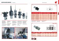
0 50U-TRONICSizesU-TRONIC <strong>180</strong> BH10 255M12 prof.fil.20E119028621773311.525Cø 125 2515CM6 prof.fil.120 -0.00525E2Ø 4445°45°29.5 184140324806321.51D-0.005-0.008Ø 50Ø 81Ø 160 H6Ø 220+0.02+0.04 prof.2120.01+0.0212 +0.04+0.0212 +0.0425 25AØ 22330 ±0.01 30 ±0.01U-TRONIC <strong>200</strong> BH10255M12 prof.fil.2044 62E12519028621773311.537.5CØ 275Ø <strong>200</strong> 37.515C0-0.00545°45°184 140324806321.5-0.005-0.008Ø 50Ø 81Ø 160 H6Ø 220+0.02+0.04 prof.2120.010 7525 25M6 prof.fil.121E2Ø 4429.5D+0.0212+0.04+0.0212+0.04A60 ±0.01 60 ±0.01A = Coolant outletC = Radial trasverseD = Coolant wayE1 = Electric connectorsEncoder-Limit stopE2= Electric connectorsServomotor
SizesD’ANDREAU-TRONIC 3/325 S1881310252G Ø 25Ø798389838 F Ø 8.516M10x178402351329.517M16x1.5+0.125.57°7'30''0AB98 9838 3822 22120 120<strong>180</strong>15512527Ø 70 H7Ø 140Ø 196.869Ø 325M8 prof.fil.161301301Ø 22.21512 H84DE115 44E2H gr.6325100C12209299.5274.52513U-TRONIC 5/400 S1995.5136G Ø 57.5210 210190.5105 10560 6045208105M10 prof.fil.1625 H7 prof.9Ø 400146 146230<strong>200</strong>M10x1160469.55M20x1.540Ø 131 H7Ø 210Ø 2420-0.1 Ø 285.775Ø 500+0.125.57°7'30''0AB45 1660 60110 11082M10 prof.fil.16F Ø 8.5120Ø 25.420Ø 400181.86181.8650.7H gr.812512 H8DE1E2C4.5A = Coolant outletB = Presetting blockC = Radial trasverseD = Coolant wayE1 = Electric connectorsEncoder-Limit stopE2= Electric connectorsServomotorF = 0.5-1 BAR air intake forinner pressurizationG = Cables wayH = Camlock
U-TRONICSizes210 210190.5G Ø 57.5105 10560 604520810512M10 prof.fil.1625 H7 prof.920919146 146230<strong>200</strong>M10 prof.fil.16M10x1160303.5278.5103.5501369.5525M20x1.540Ø 131 H713Ø 242Ø 2100-0.1 Ø 285.775Ø 500+0.125.5 07°7'30''U-TRONIC 5/500 SAB060 60 82110 110181.86 181.86F Ø 8.512 H81DE12050.7E2HØ 25.420500160C4.520913U-TRONIC 5/630 S1246 64G Ø 57.5210 210190.5105 10560 6045208Ø 500105M10 prof.fil.1625 H7 prof.919146146230<strong>200</strong>M10x1160103.550303.5278.51369.5525M20x1.540Ø 131 H7Ø 210Ø 242-0.1 Ø 285.775+0.107°7'30''025.5A0B60110181.8660110181.8682M10 prof.fil.16F Ø 8.512 H81DE120E250.7Ø 25.4H20630<strong>200</strong>C4.5A = Coolant outletB = Presetting blockC = Radial trasverseD = Coolant wayE1 = Electric connectorsEncoder-Limit stopE2= Electric connectorsServomotorF = 0.5-1 BAR air intake forinner pressurizationG = Cables wayH = Camlock gr.8
SizesD’ANDREA2610U-TRONIC 8/800 S365.555 554514G2215390430395232 432135M24 prof.fil.40ABM10 prof.fil.20M24 prof.fil.4030080 8055 5525 H7 prof.85015°10°95350247.5100100247.5350100310250100250 250Ø 205 H7Ø 320Ø 382Ø 500 H4Ø 800M12 prof.fil.24100175247.5350100247.5350E2M14x1.51D Ø 105025800280CF Ø 8.514 H941732.2 H82610U-TRONIC 8/1000 S435Ø 800365.555 554514G2295158400223214335M24 prof.fil.40ABM10 prof.fil.2025 H7 prof.8Ø 100030055 5515°5080 8010°95100100350247.5247.5350320260100 100250 250Ø 205 H7Ø 320Ø 382Ø 500 H447 16M24 prof.fil.40100175247.5350100247.5350M12 prof.fil.24E2M14x1.51 50D Ø 1025950350CF Ø 8.514 H951732.2 H8A = Coolant outletB = Presetting blockC = Radial trasverseD = Coolant wayE2= Electric connectorsServomotorF = 0.5-1 BAR air intake forinner pressurizationG = Cables way
U-TRONICElectric componentsBURNDY CONNECTORUTG6 16-19 SNBURNDY CONNECTORUTG0 16-19 PHBURNDY CONNECTORUTG0 14-12 PHBURNDY CONNECTORUTG6 14-12 SNSIEMENS CONNECTOR6FX<strong>200</strong>3-OCE126FX<strong>200</strong>3-OCE17(DIGITAL)SIEMENS CONNECTOR6FX<strong>200</strong>3-OCE10LIMIT SWITCHKW4203K6U375ABC++__111323121323232U-TRONIC <strong>180</strong> - <strong>200</strong> BHEFDRGHJACBTSMLPKNVUBURNDY CONNECTORUTG6 16-19 SNCOD. 30.141.1.02.1619BURNDY CONNECTORUTG0 16-19 PHCOD. 30.141.1.03.1619ENCODER (E)ROD 426-E/500 pulse/revLIMIT SWITCHKW4203K6U375SIEMENS A.C. SERVOMOTOR1FT5046-1AK71SIEMENS A.C. SERVOMOTOR1FT6044-A4K71 DIGITALUa2+5VUa0Ua0Ua1Ua1_Ua2screenV+5VVENCODER (E)ROD 426-E/125 pulse/revPINKBLUEREDBLACKBROWNGREENYELLOWGRAYWHITE-BROWN0.5 mm 20.5 mm 2WHITEWHITEBROWNABCDEFGHJKLMBURNDY CONNECTORUTG6 14-12 SNCOD. 30.141.1.02.1412BURNDY CONNECTORUTG0 14-12 PHCOD. 30.141.1.03.1412U-TRONIC 3/325 S48 66BURNDY CONNECTORUTG0 14-12 PHBURNDY CONNECTORUTG6 14-12 SNBURNDY CONNECTORUTG6 16-19 SNSIEMENS CONNECTOR6FX<strong>200</strong>3-OCE10SIEMENS CONNECTOR6FX<strong>200</strong>3-OCE126FX<strong>200</strong>3-OCE17(DIGITAL)BURNDY CONNECTORUTG0 16-19 PHLIMIT SWITCHKW4203K6U1500ABC++__111323123123232EFDRGHJACBTSMLPKNVUBURNDY CONNECTORUTG6 16-19 SNCOD. 30.141.1.02.1619BURNDY CONNECTORUTG0 16-19 PHCOD. 30.141.1.03.1619SIEMENS A.C. SERVOMOTOR1FT5034-1AK71SIEMENS A.C. SERVOMOTOR1FT6034-4AK71 DIGITALENCODER (E)ROD 426-E/500 pulse/revLIMIT SWITCHKW4203K6U1500Ua2+5VUa0Ua0Ua1Ua1PINKBLUEREDBLACKBROWNGREENYELLOWGRAY¯Ua2screen WHITE-BROWN¯ 0.5 mm 2WHITE+5V 0.5 mm 2BROWN¯ WHITEENCODER (E)ROD 426-E/500 pulse/revABCDEFGHJKLMBURNDY CONNECTORUTG6 14-12 SNCOD. 30.141.1.02.1412BURNDY CONNECTORUTG0 14-12 PHCOD. 30.141.1.03.1412A= END OF STROKEB= EMERGENCYC= RESET(E): For digital servomotor,encoder on request
Electric componentsD’ANDREASIEMENS A.C. SERVOMOTOR1FT5046-1AK71SIEMENS A.C. SERVOMOTOR1FT6044-4AK71 DIGITALU-TRONIC 5/400 - 5/500 - 5/630 SABCLIMIT SWITCHKW4203K6U1500++__111323123123232EFDRGHJACBTSMLPKNVUBURNDY CONNECTORUTG6 16-19 SNCOD. 30.141.1.02.1619BURNDY CONNECTORUTG0 16-19 PHCOD. 30.141.1.03.1619LIMIT SWITCHKW4203K6U1500ENCODER (E)ROD 426-E/500 pulse/revBURNDY CONNECTORUTG0 16-19 PHBURNDY CONNECTORUTG0 14-12 PHBURNDY CONNECTORUTG6 16-19 SNBURNDY CONNECTORUTG6 14-12 SNSIEMENS CONNECTOR6FX<strong>200</strong>3-OCE126FX<strong>200</strong>3-0CE17 (DIGITAL)SIEMENS CONNECTOR6FX<strong>200</strong>3-OCA10Ua2+5VUa0Ua0Ua1Ua1¯Ua2screen¯+5V¯0.5 mm 20.5 mm 2WHITEENCODER (E)ROD 426-E/500 pulse/revPINKBLUEREDBLACKBROWNGREENYELLOWGRAYWHITE-BROWNWHITEBROWNABCDEFGHJKLMBURNDY CONNECTORUTG6 14-12 SNCOD. 30.141.1.02.1412BURNDY CONNECTORUTG0 14-12 PHCOD. 30.141.1.03.1412U-TRONIC 8/800 - 8/1000 SSIEMENS A.C. SERVOMOTOR1FT5 074-1AF71SIEMENS A.C. SERVOMOTOR1FT6084-84F71 DIGITALSIEMENS CONNECTOR6FX<strong>200</strong>3-OCA106FX<strong>200</strong>3-OCB10(DIGITAL)SIEMENS CONNECTOR6FX<strong>200</strong>3-OCA126FX<strong>200</strong>3-OCE17(DIGITAL)0.3 m1 mLIMIT SWITCHKW4203K6U1500ABC++__111323121323232EFDRGHJACBTSMLPKNVUCABLES LENGTH = 1 m.49 16LIMIT SWITCHKW4203K6U1500ENCODER (E)ROD 426-E/500 pulse/revUa2 PINK+5V BLUEUa0 REDUa0 BLACKUa1 BROWNUa1 GREEN- YELLOWUa2 GRAYscreen WHITE-BROWN- 0.5 mm 2+5V 0.5 mm 2- WHITEENCODER (E)ROD 426-E/500 pulse/revWHITEBROWNABCDEFGHJKLMCABLES LENGTH = 0,3 m.A= END OF STROKEB= EMERGENCYC= RESET(E): For digital servomotor,encoder on request
U-TRONICAssembly/GeneralitiesU-TRONIC BHU-TRONIC SCAMLOCKThe BH U-TRONICS are applied manuallyor automatically using the taper forrotation and a flange for fastening.The other U-TRONICS, fitted with rotationplate in place of the taper, are applied:a. manually, with a camlock flange forquick fasteningb. automatically with palletized systemsand special connectors.50 68
U-TRONIC <strong>180</strong>-<strong>200</strong> BH assemblyD’ANDREACABD0.80.80.005 A0.80.01X0.8EOn machines with fixedspindle- Mount the U-TRONICwith the taper and withoutflange on the machinespindle and measureexactly the ‘X’ distancewith a tolerance of ±0.005mm.- Make the flange with ‘X’distance and a toleranceof ±0.005 mm.- Mount the U-TRONIC withthe taper and the flange onthe machine spindle andtighten the screws.On machines with axialspindle stroke (boringmachines)- Make the flange withsupport surfaces parallelin 0.01 mm tolerance.- Mount the U-TRONIC withthe taper and the flangeon the machine spindle.- Retract the spindle untilthe flange rests lightlyagainst the front surfaceof the boring machine head.- Block the axial stroke of theboring machine spindle.- Tighten the flange screws.B = Center the boringmachine spindleC = FlangeD = ArborE = Stud Bolt51 16
U-TRONICFLANGE - Construction exampleCU-TRONIC 325 S15.9 ±0.198 ±0.0598 ±0.050.01A10.054.1.1.0010.00.01AA0.8CAMLOCK KIT98 ±0.0598 ±0.056°35'16"45°ø 227.8ø 32557 B0.85.3ø 165M8ø 13.57°7'30"+0.0150D196.869G n°4 23+0.05010.055.1.060.02320.010.0.15.0817ø 25.6 +0.04+0.080.839.42.001.325.00consisting of:n°4 camlock camsn°4 pins for camsn°4 springs for camsn°1 keyn°1 M10 eyebolt10.160.1.02.06.0010.150.07.01<strong>200</strong> F0.823.846 min.14E0.01U-TRONIC 5-... S181.86 ±0.05181.86 ±0.050.01AC10.054.1.1.0016.0A0.80.01 A0.852 7015°15°ø 3654°59'8"105 ±0.05105 ±0.05210 ±0.05 210 ±0.05ø 500B5.37°7'30"ø 250+0.02ø 285.775 0CAMLOCK KIT76DM8ø 13.539.42.001.500.00consisting of:n°6 camlock camsn°6 pins for camsn°6 springs for camsn°1 keyn°2 M16 eyebolt+0.05H n°6 26 018.25 ±0.110.055.1.060.023 20.010.0.15.081810.160.1.02.08.0010.150.07.01400 F0.8+0.04ø 28.5 +0.082753 min.0.815E0.01B= Center the boringmachine spindleC= EyeboltD= Control with GaugeE= Size to controldepending on thespindle protrusionF= Control wrenchG= Bores min. depth 46H= Bores min. depth 53
U-TRONICToolholdersU-TRONIC <strong>180</strong> - <strong>200</strong> BHP110P111T 214 RARBORT 214 LP101U-TRONICFLANGEP100K03consisting of:P 100P 101P 110P 111T 214 LT 214 RREF. K03 UT <strong>180</strong>/BH K03 UT <strong>200</strong>/BHCODE 50 04 182 03 000 50 04 182 03 000ARBORS54 72REF. UT <strong>180</strong>/BH UT <strong>200</strong>/BHISO 40 - ISO 45 - ISO 50 ISO 40 - ISO 45 - ISO 50
Toolholders and headsD’ANDREAP100P101UT <strong>180</strong> - <strong>200</strong>/BHREF. CODE D HP 100 43 15 60 40 100 010040P 101 43 15 60 40 160 0 160UT <strong>180</strong> - <strong>200</strong>/BHREF. CODE S LP 110 43 35 60 40 120 012035P 111 43 35 60 40 <strong>180</strong> 0 <strong>180</strong>T214 LDT 214 R95°ADHP110P111SLT 214LT 214RFREF. CODE A D F55 17UT <strong>180</strong> - <strong>200</strong>/BHT 214 L 46 02 040 12 9 10T 214 R 46 02 040 12 9 2040 40 28 CCMT 1204.. 49 40 1 0005009 10 150 09 0250 0
U-TRONICToolholdersU-TRONIC 325 - 400 - 500 - 630 - 800 - 1000 SB50B 1525x25TU 80/95.2516CA ISO5611B 01MRPC 11.50TP 80/90.50FLANGEU-TRONICB 02PC 12.5056 74K03consisting of:B01B02B15MRTUREF.UT3/325S 50 17 0325 9 3 00UT5/400SUT5/500S 50 17 0500 9 3 00UT5/630SUT8/800S50 17 0800 9 3 00UT8/1000SToolholder with automatictool changeB50UT5/400SREF.UT5/500SB50 HSK - A63 - A100UT5/630SB50 DIN69871-A - B50UT8/800SB50 MAS BT50UT8/1000S
ToolholdersD’ANDREAAHB01/B02L1LØ d1 H7Ø d2REF. CODE A d1 d2 H L L1 kgUT3/325SB01 UT 3 44 3 0 050 0115 0 150 50 80 135 100 23 5.5B02 UT 3 44 3 0 050 0275 0 150 50 80 135 260 23 8.5UT5/400S B01 UT 5 44 3 0 063 0155 0 <strong>200</strong> 63 100 170 155 30 11UT5/500SUT5/630S B02 UT 5 44 3 0 063 0365 0 <strong>200</strong> 63 100 170 400 30 19UT8/800S B01 UT 8 44 3 0 080 0230 0 250 80 130 <strong>200</strong> 230 30 25UT8/1000S B02 UT 8 44 3 0 080 0720 0 250 80 130 250 720 30 60Ø d2AH1L1Ø d1 H7LHB15REF. CODE A d1 d2 H H1 L L1 kgUT3/325S B15 UT 3 44 5 0 050 0190 0 150 50 80 190 135 60 23 3.7UT5/400SUT5/500S B15 UT 5 44 5 0 063 0250 0 <strong>200</strong> 63 100 270 170 70 30 7.5UT5/630SUT8/800SUT8/1000SB15 UT 8 44 5 0 080 0300 1 250 80 130 300 <strong>200</strong> 85 30 30Ø d1 -0.01-0.03L1LL2MHD' 80Ø d2MRREF. CODE d1 d2 L L1 L2 kgUT3/325S MR 50/80.80 45 02 080 0106 0 50 80 95 50 45 1.6UT5/400SUT5/500S MR 63/98.80 45 02 098 0106 0 63 98 105 60 45 3UT5/630SUT8/800SUT8/1000S MR 80/130.80 45 02 130 0124 0 80 130 125 78 45 7MHD' 8065902525Ø 95TUREF. CODE kgUT3/325SUT5/400SUT5/500S TU 80/95.25 46 05 080 25 0 01 4UT5/630SUT8/800SUT8/1000Sd2MHD' 804085TPUT3/325SUT5/400SUT5/500SUT5/630SUT8/800SUT8/1000SREF. CODE d2 kgTP 80/90.50 46 04 080 50 0 01 90 2.3TP 80/125.50 46 04 080 50 0 02 125 3.257 17501650205516CA59PCUse 16CA ISO5611 cartridges (see p.77)BREF. CODE B kgUT3/325SUT5/400SPC 11.50 43 30 50 16 095 0 95 1.3UT5/500S PC 12.50 43 30 50 16 135 0 135 2UT5/630S PC 13.50 43 30 50 16 <strong>200</strong> 0 <strong>200</strong> 3.2UT8/800SUT8/1000SPC 14.50 43 30 50 16 300 0 300 5
U-TRONICTechnical dataHP232512.8"D C/225510"PDP111P110ø E max.ø F max.P1P100P101ø M max.ø N max.C/2PP2P1D CBø F max.ø M max.ø N max.SH58 76TECHNICAL DATA UT <strong>180</strong> BH UT <strong>200</strong> BH UT 325 SRadial trasverse C mm inch 50 1.97” 75 2.95” 100 3.94”Feed mm/min. inch/min. 1÷500 .04”÷19.7” 1÷500 .04”÷19.7” 1÷400 .04”÷15.75”Rapid trasverse mm/min. inch/min. 500 19.7” 500 19.7” 400 15.75”Maximum rotation min -1 RPM 1000 800 500Torque da Nm lb ft. 100 740 100 740 350 2590Radial force da N pound 250 562.5 250 562.5 300 675Weight Kg pound 32 70.4 40 88 110 242Ø B mm inch - - - - 325 12.8”Ø D mm inch <strong>180</strong> 7.090” <strong>200</strong> 7.87” 325 12.8”H mm inch - - - - 235 9.25”S mm inch - - - - 125 4.92”Ø E x P mm inch 240 x 75 9.45”x 3” 350 x 75 13.78”x 3” - -Ø F x P mm inch 360 x 75 14.17”x 3” 450 x 75 17.7”x 3” 650 x 140 25.5”x 10.5”Ø M x P2 mm inch 125 x <strong>200</strong> 4.92”x 7.87” <strong>180</strong> x <strong>200</strong> 7”x 7.87” 360 x 400 13.9”x 15.75”Ø N x P1 mm inch 165 x 140 6.5”x 5.5” 250 x 140 9.84”x 5.5” 560 x 240 20”x 9.45”Repeatibility accuracy mm inch 0.003 .00012” 0.003 .00012” 0.003 .00012”Boring accuracy H7 H7 H7 H7 H7 H7Facing accuracy mm inch 0.010 .0004” 0.010 .0004” 0.010 .0004”Max. chip removal on C40 steel mm 2 inch 2 2 .0031” 2.5 .0039” 5 .0078”Roughness Ra µin 1.6 63” 1.6 63” 1.6 63”
Technical dataD’ANDREAUT 5 400 S UT 5 500 S UT 5 630 S UT 8 800 S UT 8 1000 S125 4.92” 160 6.3” <strong>200</strong> 7.87” 280 11.03” 350 13.78”1÷400 .04”÷15.75” 1÷400 .04”÷15.75” 1÷400 .04”÷15.75” 1÷500 .04”÷19.7” 1÷500 .04”÷19.7”400 15.75” 400 15.75” 400 15.75” 500 19.7” 500 19.7”400 315 250 <strong>200</strong> 160800 5920 800 5920 800 5920 1000 7400 1000 7400500 1125 500 1125 500 1125 1000 2250 1000 2250<strong>200</strong> 440 230 506 350 770 1<strong>200</strong> 2700 1500 337559 17500 19.7” 500 19.7” 500 19.7” 800 31.5” 800 31.5”400 15.75” 500 19.7” 630 24.8” 800 31.5” 1000 39.37”274.5 10.8” 278.5 10.96” 278.5 10.96” 395 15.55” 400 15.75”160 6.3” 160 6.3” 160 6.3” <strong>200</strong> 7.87” <strong>200</strong> 7.87”- - - - - - - - - -800 x 150 31.5”x 6” 1000 x 150 39.5”x 6” 1250 x 150 49”x 6” 1600 x 160 63”x 6.3” <strong>200</strong>0 x 160 79”x 6.3”450 x 540 17.7”x 21.26” 560 x 540 22”x 21.26” 700 x 540 27.6”x 21.26” 850 x 860 33.5”x 33.8” 1050 x 860 41.5”x 33.8”680 x 295 26.8”x 11.6” 850 x 295 33.5”x 11.6” 1050 x 295 41.4”x 11.6” 1250 x 370\ 49.2”x 14.5” 1600 x 370 63”x 14.5”0.003 .00012” 0.003 .00012” 0.003 .00012” 0.005 .0002” 0.005 .0002”H7 H7 H7 H7 H7 H7 H7 H7 H7 H70.01 .0004” 0.015 .0006” 0.015 .0006” 0.020 .0008” 0.020 .0008”9 .014” 9 .014” 9 .014” 14 .0217” 14 .0217”1.6 63” 1.6 63” 1.6 63” 1.6 63” 1.6 63”