Profibus System Integration PDF 4.03MB - Schneider Electric
Profibus System Integration PDF 4.03MB - Schneider Electric
Profibus System Integration PDF 4.03MB - Schneider Electric
- No tags were found...

You also want an ePaper? Increase the reach of your titles
YUMPU automatically turns print PDFs into web optimized ePapers that Google loves.
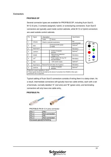
ConnectorsPROFIBUS DPSeveral connector types are available for PROFIBUS DP, including 9-pin Sub-D,M-12 (5 pins, 3 contacts assigned), hybrid, or screw/spring connectors. 9-pin Sub-Dconnectors are typically used inside control cabinets, while M-12 or hybrid connectorsare used outside control cabinets.Pin Signal Descriptionl1234567(Shield)M24RxD/TxD-PCNTR-PDGNDVP aP24CableDeviceShield or potential equalizationGround of 24V powersupplyControl of repeaterdirectionData ground (referencevoltage to VP)Power supply +5v (e.g. forbus termination)+24V power supplySpecificationNotrecommendedOptional bMandatoryOptional bMandatoryMandatoryOptional b1 5698RxD/TxD-NReceive/Transmit data; line A (green)Control of repeaterdirectionMandatoryOptional b9 CNTR-Na Minimum current capabillity is 10mAb These signals should be provided by the device if converters from RS485 to fibre optictrasmission are to supportedTypical cabling of 9-pin Sub-D connectors consists of wiring them in a daisy-chain. Asa result, intermediate connectors will typically have two cable entries, each with a setof terminals, normally labelled “A” (red wire) and “B” (green wire), and terminatingconnectors will only have one cable entry.PROFIBUS PAPROFIBUS PA M-12 4 pins connectorPin 1 PA+Pin 2 Not connectedPin 3 PA-Pin 4 Not connectedScrewed gland Schelding31