

Pressure Limiting Valve Model 200-64B - FMC Technologies
Pressure Limiting Valve Model 200-64B - FMC Technologies
Pressure Limiting Valve Model 200-64B - FMC Technologies

You also want an ePaper? Increase the reach of your titles
YUMPU automatically turns print PDFs into web optimized ePapers that Google loves.
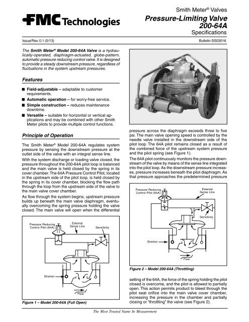
Issue/Rev. 0.1 (5/13)Smith Meter ® <strong>Valve</strong>s<strong>Pressure</strong>-<strong>Limiting</strong> <strong>Valve</strong><strong>200</strong>-64ASpecificationsBulletin SS03016The Smith Meter ® <strong>Model</strong> <strong>200</strong>-64A <strong>Valve</strong> is a hydraulically-operated,diaphragm-actuated, globe-pattern,automatic pressure reducing control valve. It is designedto provide a steady downstream pressure, regardless offluctuations in the system upstream pressures.FeaturesField-adjustable – adaptable to customerrequirements.Automatic operation – for worry-free service.Simple construction – reduces maintenancedowntime.Versatile – suitable for horizontal or vertical applicationsand may be combined with other SmithMeter pilots to provide multiple control functions.Principle of OperationThe Smith Meter ® <strong>Model</strong> <strong>200</strong>-64A regulates systempressure by sensing the downstream pressure at theoutlet side of the valve with an integral sense line.With the system discharge or loading valve closed, thepressure throughout the <strong>200</strong>-64A pilot loop is balancedand the main valve is held closed by the spring in itscover chamber. The 64A <strong>Pressure</strong> Control Pilot, locatedin the upstream side of the pilot loop, is held closed bythe spring in its cover chamber, blocking the flow paththrough the loop from the upstream side of the valve tothe main valve cover chamber.As flow through the system begins, upstream pressurebuilds up beneath the main valve diaphragm, eventuallyovercoming the spring pressure holding the valveclosed. The main valve will open when the differentialpressure across the diaphragm exceeds three to fivepsi. The main valve opening speed is controlled by theneedle valve installed in the downstream side of thepilot loop. The 64A pilot remains closed as a result ofthe combined force of the upstream system pressureand the pilot spring (see Figure 1).The 64A pilot continuously monitors the pressure downstreamof the valve by means of the sense line integratedinto the pilot loop. As the downstream pressure increases,pressure increases beneath the pilot diaphragm. Asthat pressure approaches the predetermined pressure<strong>Pressure</strong> ReducingControl Pilot (64A)ExternalSense LineSensitivity<strong>Pressure</strong> ReducingControl Pilot (64A)ExternalSense LineSensitivityStrainerFlowFigure 2 – <strong>Model</strong> <strong>200</strong>-64A (Throttling)StrainerFlowFigure 1 – <strong>Model</strong> <strong>200</strong>-64A (Full Open)setting of the 64A, the force of the spring holding the pilotclosed is overcome, and the pilot is allowed to partiallyopen. This action permits product to bleed through thepilot seat orifice into the main valve cover chamber,increasing the pressure in the chamber and partiallyclosing or “throttling” the valve (see Figure 2).The Most Trusted Name In Measurement
The partial closing of the <strong>200</strong>-64A valve limits productflow through the valve and reduces the downstreamsystem pressure. An excessive reduction in downstreampressure due to changes in the demands of the systemwill automatically be sensed by the 64A pilot and it will,in turn, allow an increase in product flow by closing orpartially closing the flow path feeding the main valvecover chamber permitting the main valve to operatesufficiently to satisfy those demands.ApplicationsThe Smith Meter <strong>Model</strong> <strong>200</strong>-64A is a modulating controlvalve that can be used in most non-dead-end servicesystem designs where protection of downstream equipmentfrom excessive pump pressure is required.The control range of the <strong>Model</strong> <strong>200</strong>-64A is advantageousfor installations where pressure loss is a primaryconcern since it creates a low pressure drop while inthe modulating mode. This is a result of the sensitivity(closing speed) needle valve being installed in thedownstream side of the <strong>200</strong>-64A pilot loop.The control range of the <strong>Model</strong> <strong>200</strong>-64A is limited to flowrates above 5% of the nominal maximum flow.Additional control functions can be added to the<strong>200</strong>-64A pressure-reducing control valve. Included aresolenoid block (<strong>Model</strong> 30A), maximum rate-of-flow control(<strong>Model</strong> 40A), back-pressure control (<strong>Model</strong> 60A) andcheck and thermal relief (<strong>Model</strong> 80B/07).SpecificationsNominal Flow RatingsFlowSize USGPM L/min Cv +2" 130 492 503" 420 1,600 1334" 600 2,250 2046" 1,000 3,750 436+ <strong>Pressure</strong> Drop: DP (psi) = Sp. Gr.(Q(USGPM)Cv)2Materials of ConstructionComponent Body Internals Seals<strong>Model</strong> <strong>200</strong>09SCStrainerNeedle <strong>Valve</strong>,<strong>Model</strong> 1364ACarbonSteelCarbonSteelCarbonSteelCarbonSteelTemperature RangeDiaphragm<strong>Valve</strong>sSeal MaterialStainless Steel,Carbon Steel,Ductile IronBuna-N orViton304 Stainless Steel –Carbon Steel300 Stainless Steel,Carbon SteelPilotsViton O-ringw/PTFE 1BackupVitoN (Std.),BunaTemperatureRangeBuna-N + Viton + 0°F to 160°FViton Viton + 10°F to 350°F+ Standard; for other elastomers, consult factory.Weight<strong>Model</strong> Size Weight – lb (kg)<strong>200</strong>-64AOrdering InformationOperatingConditionsSeals2"3"4"6"* Minimum, normal and maximum.48 (22)85 (39)138 (63)260 (118)Liquid – name and sp. gr., or APIgravity, temperature range*, viscosity range*,maximum working pressure, andpressure settings.Buna-N, VitonMaximum Product Viscosity<strong>200</strong> SSU (40 mPa•s). Above <strong>200</strong> SSU, consult factory.1 mPa•s = 1 cP.<strong>Pressure</strong> RatingClass 150 ANSI, 285 psi (19.6 bar).Class 300 ANSI, 300 psi (20.7 bar).At 100°F (37.8°C), derated per ASME B16.5.1 Polytetrafluoroethylene (PTFE).Page 2 • SS03016 Issue/Rev. 0.1 (5/13)
DimensionsInches (mm)<strong>Model</strong>SizeAClass150A1Class300B + C D + EPilots and Tubing Pilots and TubingB++BCC2"8.0(203)8.5(216)8.0(203)4.0(102)7.5(140)3.0+(76) DD+PilotsandTubingPilotsandTubing<strong>200</strong>-64A3"4"11.0(279)13.5(343)11.8(299)14.2(362)9.5(241)9.5(241)4.0(102)4.9(124)9.5(241)9.5(241)4.1(105)4.5(114)EE6"17.0(432)17.9(454)11.0(279)6.6(168)12.5(318)5.5(140)A - Class 150 A - ANSI Class 150 ANSIA1 - Class 300 A1 - ANSI Class 300 ANSINote: Dimensions – Inches to the nearest tenth (millimetres to the nearest whole mm), each independently dimensioned from respectiveengineering drawings.+ Pilots and tubing will be within these dimensions.Issue/Rev. 0.1 (5/13) SS03016 • Page 3
Revisions made to SS03016 rev. 0.1 (5/13):Limited status removed.Page 2: Specifications: 8" removed from Nominal Flow Ratings. Weight: 8" removed.Page 3: 8" removed from Dimensions.Editorial Change: 11/13 - Seal reference was changed to PTFE.Headquarters:500 North Sam Houston Parkway West,Suite 100, Houston, TX 77067 USAPhone: +1 (281) 260 2190Fax: +1 (281) 260 2191Operations:Measurement Products and Equipment:Ellerbek, Germany +49 (4101) 3040Erie, PA USA +1 (814) 898 5000Integrated Measurement Systems:Corpus Christi, TX USA +1 (361) 289 3400Kongsberg, Norway +47 (32) 286700The specifications contained herein are subject to change without notice and any user of saidspecifications should verify from the manufacturer that the specifications are currently in effect.Otherwise, the manufacturer assumes no responsibility for the use of specifications whichmay have been changed and are no longer in effect.Contact information is subject to change. For the most current contact information, visit ourwebsite at www.fmctechnologies.com/measurementsolutions and click on the “Contact Us”link in the left-hand column.www.fmctechnologies.com/measurementsolutionsPrinted in U.S.A. © 5/13 <strong>FMC</strong> <strong>Technologies</strong> Measurement Solutions, Inc. All rights reserved. SS03016 Issue/Rev. 0.1 (5/13)


