El In-Place Inclinometer Datasheet - Slope Indicator
El In-Place Inclinometer Datasheet - Slope Indicator
El In-Place Inclinometer Datasheet - Slope Indicator
- No tags were found...

Create successful ePaper yourself
Turn your PDF publications into a flip-book with our unique Google optimized e-Paper software.
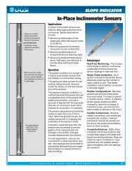
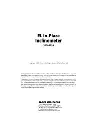
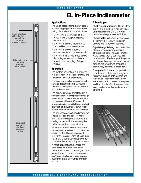
S L O P E I N D I C A T O R13EL <strong>In</strong>-<strong>Place</strong> <strong>In</strong>clinometerSensors are installedwith the fixed wheelpointing in thedirection ofexpected movement<strong>In</strong>clinometer casingcontrols theorientationof the sensorsGauge lengthof each sensoris the distancebetween pivotpoints.ApplicationsThe EL in-place inclinometer is idealfor data logging and real-time monitoring.Typical applications include:• Monitoring deformation of diaphragmwalls supporting deepexcavations.• Monitoring ground movementsinduced by tunnel construction.• Monitoring deformations ofembankments and retaining walls.• Monitoring landslide areas abovedams, highways, and railroads toprovide early warning of slopefailure.OperationThe system consists of a number ofin-place inclinometer sensors that areinstalled in inclinometer casing.The casing provides access for subsurfacemeasurements. Groovesinside the casing control the orientationof the sensors.The casing is typically installed in avertical borehole that passes througha suspected zone of movement intostable ground below. One set ofgrooves is aligned with the expecteddirection of movement, down hill ortowards an excavation, for example.The sensors are positioned inside thecasing to span the zone of movement.When the ground moves, thecasing moves with it, changing theinclination of the sensors inside.<strong>In</strong>clination measurements from thesensors are processed to provide thecasing profile, the displacement inmm for the gauge length of each sensor,and the cumulative displacementin mm for the entire string of sensors.<strong>In</strong> most applications, sensors areconnected to a data acquisitionsystem, and data processing is completedby a computer program suchas Argus, which can trigger alarmsbased on a rate of change or othercriteria.AdvantagesReal Time Monitoring: The in-placeinclinometer is ideal for continuous,unattended monitoring and candeliver readings in near-real time.Removable: Wheeled sensors canbe removed to allow verificationchecks with a traversing probe.Rigid Gauge Tubing: Accurate displacementcalculations requirestraight-line sensor gauge lengths.Rigid gauge tubing satisfies thisrequirement. Rigid gauge tubing alsoprovides reliable performance in softground, where abrupt changes inprofile may occur at a shear zone.Complete Solutions: <strong>Slope</strong> <strong>In</strong>dicatoroffers complete monitoring solutionsthat include data loggers andArgus web-based monitoring software,which can present profile plotsand trend plots of inclinometer datajust minutes after the readings areobtained.G E O T E C H N I C A L & S T R U C T U R A L I N S T R U M E N T A T I O N
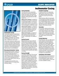
14W W W . S L O P E I N D I C A T O R . C O MSYSTEM CONFIGURATIONA complete IPI system includes inclinometercasing, IPI sensors, signal cable, suspension kit,suspension cable, data logger, and software.<strong>In</strong>clinometer Casing: Choose 85 mm or 70 mm(3.34" or 2.75) diameter inclinometer casing.Standard or Multiplexed Sensors: Standardsensors have independent signal cables. Thisoffers the greatest flexibility for placement butlimits the number of sensors that can be installedin one casing. Multiplexed sensors share a signalcable, but must be placed within 3 meters ofeach other.Uniaxial or Biaxial Sensors: Uniaxial sensorsmeasure tilt in the plane of the wheels. Biaxialsensors have a second sensor that measures tiltin the plane perpendicular to that of the wheels.Wheels: Order wheels for each sensor. Choosewheels to fit 85 or 70 mm casing.Tubing for Gauge Lengths: Order gauge tubingfor each sensor. Tubing is sized to make exactgauge lengths of 1, 2, or 3 meters. Three metersis the maximum recommended gauge length.Signal Cable: Order signal cable for each standardsensor. Cable runs from the location of thesensor to the location of the data logger.For multiplexed systems, order a jumper cableconnector and signal cable to run from the topsensor to the location of the data logger.Suspension Kit: Order one suspension kit foreach installation. The kit includes a top wheelassembly, clamps and thimbles, a chain for fineadjustments, and an S hook. Cable not included.<strong>In</strong>-Line Suspension Kit: The in-line suspensionkit is used when it is necessary to monitor two ormore zones in the borehole. It allows sensors atdeeper zones to be suspended from sensorsabove. The kit includes a top wheel assembly forthe sensor below, clamps and thimbles, and ahanger that threads onto the sensor above.Cable not included.Data Loggers: <strong>Slope</strong> <strong>In</strong>dicator recommendsusing Campbell Scientific CR10X data loggers.Two biaxial sensors or three uniaxial sensors canbe connected directly to the CR10 or up to 16uniaxial or biaxial sensors can be connected toan AM 16/32 multiplexer. With multiplexed sensors,up to six string of five sensors each can beconnected. No multiplexer is required.Software: Communication software is requiredto retrieve data from the data logger. Data reductionsoftware, such as Argus, is used to processand plot the data.STANDARD IPI SENSORSUniaxial IPI Sensor . . . . . . . . . . . . 56804121Biaxial IPI Sensor . . . . . . . . . . . . . 56804122Wheels for 85mm Casing . . . . . . . 56805032Wheels for 70 mm Casing . . . . . . 56805022Tubing for 1 m Gauge Length. . . . 16804221Tubing for 2 m Gauge Length. . . . 16804222Tubing for 3 m Gauge Length. . . . 16804223Signal Cable . . . . . . . . . . . . . . . . . 50613527MULTIPLEXED IPI SENSORSUniaxial IPI Sensor with Mux . . . . 56804521Biaxial IPI Sensor with Mux . . . . . 56804522Wheels for 85mm Casing . . . . . . . 56805032Wheels for 70 mm Casing . . . . . . 56805022Tubing for 1 m gauge length . . . . 16804221Tubing for 2 m gauge length . . . . 16804222Tubing for 3 m gauge length . . . . 16804223Jumper Cable Connector . . . . . . . 56804510Signal Cable . . . . . . . . . . . . . . . . . 50613527SUSPENSION KITSuspension Kit, 85mm Casing . . . 56804312Suspension Kit, 70 mm Casing . . . 568043103/16" Stainless Steel Cable . . . . . 56804300IN-LINE SUSPENSION KIT<strong>In</strong>-Line Suspension Kit, 85mm . . . 56804322<strong>In</strong>-Line Suspension Kit, 70mm . . . 568043203/16" Stainless Steel Cable . . . . . 56804300IPI SENSOR SPECIFICATIONSSensor Type: <strong>El</strong>ectrolytic tilt sensor for tilt measurements,thermistor for temperature measurements.Built-in signal conditioner accepts powerinput of 5.5 to 15 Vdc and outputs ±2.5 volt differentialsignal. Biaxial version contains two tiltsensors. Multiplexed version operates from asingle signal cable.Calibrated Range: ±10 degrees.Resolution: 9 arc seconds or 0.04 mm/m usingthe CR10 data logger.Repeatability: ±22 arc seconds or ±0.1 mm/m.Calibration: 11 point calibration taken at threetemperatures from 4 to 20 °C. Optional extendedcalibration temperatures are -15 to +40 °C.Max Gauge Length: 3 meters.Required Casing: Fits 85 or 70 mm (3.34 or2.75 inch) diameter casing.Housing: Stainless steel. 38mm (1.5") diameter.Signal Cable: Signal cable, ordered separately,has seven 22-gauge tinned-copper conductors,shield, and polyurethane jacket.Suspension KitsSuspension kit containscomponents requiredto suspend sensorsfrom top of casing.One kit is requiredfor each installation.GaugeTubingSensorWheels<strong>In</strong>-line suspensionkit allows sensorsat deeper zonesto be suspendedfrom sensors above.Durham Geo <strong>Slope</strong> <strong>In</strong>dicator, 12123 Harbour Reach Drive, Mukilteo, WA, 98275 USATel: 425-493-6200 Tel: 866-916-0541 Fax: 425-493-6250 Email: solutions@slope.comCopyright 6/2009 by Durham Geo-Enterprises. Products and specifications are subject to review and change without notice.