DigiMax Intercom Specs
DigiMax Intercom Specs
DigiMax Intercom Specs
- No tags were found...

Create successful ePaper yourself
Turn your PDF publications into a flip-book with our unique Google optimized e-Paper software.
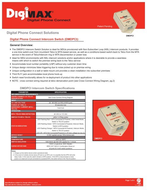
® Patent PendingDigital Phone Connect SolutionsDigital Phone Connect <strong>Intercom</strong> Switch (DMDPCI):DMDPCIGeneral Overview: The DMDPCI <strong>Intercom</strong> Switch Solution is ideal for MDUs provisioned with Non-Subscriber Loop (NSL) intercom products. It providesa one time switch-over from incumbent Telco to MTA-based service, as well as a conditions-based switch-back to Telco from the MTAservice in the event of Telco/<strong>Intercom</strong> ring or MTA disconnection or power loss Ideal for MDU environments with NSL intercom solutions and/or applications where it is desirable to provide a seamlessmeans with which to switch the premise wiring back to the Telco service Accommodate local number portability (LNP) without any customer down time Unique design minimizes false triggering due to noise picked up on premise wiring Unique confi guration in a wall or table mount unit provides a clean installation into subscriber premises Third RJ11 jack accommodates local phone hook-up Switch reset functionality allows for re-deployment of product into other applications NOTE: cross connect wiring required at telco demarcation point (see Cross Connect Wiring Diagram, pg.2)DMDPCI <strong>Intercom</strong> Switch SpecificationsDMDPCISpecifications subject to change without notice.See web site for ordering information - www.pci.comPage 1 of 4
® Patent PendingDigital Phone Connect <strong>Intercom</strong> Switch (DMDPCI):Operational Functionality:INITIAL INSTALL MODE OPERATIONDMDPCI switches premise wiring from incumbent Telco to MTA provided service on the fi rst ring from the MTA. After initial switch-over from Telco toMTA device enters into INTERCOM MODE.INTERCOM MODE OPERATIONDMDPCI maintains premises connection to MTA service until it detects a ring from the Telco service.Scenario 1:Scenario 3:If ring from Telco is detected and user is on MTA call, callwaiting tone is generated:- User can fl ash over to Telco/<strong>Intercom</strong> call- MTA call is maintained- Once Telco/<strong>Intercom</strong> call is complete DMDPCIswitches back to MTAScenario 2:If ring from Telco is detected and user is not on MTA call:- DMDPCI switches to Telco/<strong>Intercom</strong>- If user does not answer and/or answers and completesthe Telco/<strong>Intercom</strong> call the DMDPCI switches back to MTAIf MTA power is lost or MTA is disconnected:- DMDPCI switches to Telco/<strong>Intercom</strong> until power from MTA is restored- Upon detected return of MTA power the DMDPCI switches to MTAScenario 4:9V applied across Phone Port B/Y (see schematic) of DMDPCBI:- DMDPCI switches back to Telco/<strong>Intercom</strong> and is set back to INITIALINSTALL mode- Note: RESET is essential if device is to be used in a new MTAinstallation applicationPreliminaryDevice Functional SchematicLINE(LINE)Telco FromCross ConnectTo CustomerPremise WiringTelco FromCross ConnectMTAMTAn/cRingTipn/cMTA CableModem(MTA)LINERing Tip+ Local Phone9 VDC Reset-* See Cross ConnectWiring Diagram(PHONE)Cross Connect Wiring DiagramCross Connect Requirements at Telco Demarcation Pt.Incoming Single LineWiring to premise:Yellow - n/cRed - RingGreen - TipBlack - n/cTelco Demarcation Point(at Telco entrance to premise)TraditionalPremise2nd Line TipTraditionalPremise2nd Line RingSpecifications subject to change without notice.See web site for ordering information - www.pci.comPage 2 of 4
® Patent PendingDigital Phone Connect <strong>Intercom</strong> Switch (DMDPCI):Installation Instructions:1. Cross connect wiring at appropriate Telco demarcation point (see Telco Cross Connect Wiring Diagram, pg.2).2. Using 4-wire VTP, connect Line port of the Digital Phone Connect (DMDPC) to premise wiring. Any RJ11 jack in premise can beused provided continuity has been assured.3. Ensure DMDPCI is Reset. See reset instruction in # 8 below.4. Connect Output of MTA to MTA port on the DMDPC.5. Ensure MTA is powered.6. After approximately 30 seconds for the DMDPC, the LED will start to fl ash indicating that the MTA is connected and thedevice is ready for operation.7. Connect phone to Phone port of DMDPC if desired.8. After device installation, ensure Telco dial tone is present before leaving subscriber premises.9. RESET: reset needs to be held for approximately 20 seconds until LED fl ashes RED.Installation / Wiring Configuration InformationSpecifications subject to change without notice.See web site for ordering information - www.pci.comPage 3 of 4
® Patent PendingDigital Phone Connect <strong>Intercom</strong> Switch (DMDPCI):Installation / Wiring Configuration Information (cont’d)Specifications subject to change without notice.See web site for ordering information - www.pci.comPrinted in Canada501 Clements Road West, Unit 1, Ajax, ON L1S 7H4 CanadaTel (905) 428-6068 Toll Free (800) 565-7488 Fax (905) 427-1964 Toll Free Fax (866) 427-1964www.pci.com info@pci.comPage 4 of 4ISO9001REGISTEREDRev. 3/06 (P0670)