Brayton Cycle Experiment – Jet Engine - Turbine Technologies
Brayton Cycle Experiment – Jet Engine - Turbine Technologies
Brayton Cycle Experiment – Jet Engine - Turbine Technologies

You also want an ePaper? Increase the reach of your titles
YUMPU automatically turns print PDFs into web optimized ePapers that Google loves.
Instrumentation.<br />
The sensors are routed to a central access panel and interfaced with data acquisition hardware and<br />
software from National Instruments. The manufacturer provides the following description of the<br />
sensors and their location.<br />
“The integrated sensor system (Mini-Lab) option includes the following probes:<br />
Compressor inlet static pressure (P ), Compressor stage exit stagnation pressure<br />
1<br />
(P ), Combustion chamber pressure (P ), <strong>Turbine</strong> exit stagnation pressure (P ),<br />
02 3 04<br />
Thrust nozzle exit stagnation pressure (P ), Compressor inlet static temperature<br />
05<br />
(T ), Compressor stage exit stagnation temperature (T ), <strong>Turbine</strong> stage inlet<br />
1 02<br />
stagnation temperature (T ), <strong>Turbine</strong> stage exit stagnation temperature (T ), and<br />
03 04<br />
thrust nozzle exit stagnation temperature (T ). Additionally, the system includes a<br />
05<br />
fuel flow sensor and a digital thrust readout measuring real time thrust force based<br />
upon a strain gage thrust yoke system.”<br />
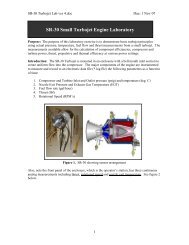
Figure 6. <strong>Turbine</strong> <strong>Technologies</strong>’s SR-30 <strong>Engine</strong><br />
Cut Away View of SR-30 <strong>Engine</strong><br />
8