Learning digital control systems with a low-cost educational platform
Learning digital control systems with a low-cost educational platform
Learning digital control systems with a low-cost educational platform

Create successful ePaper yourself
Turn your PDF publications into a flip-book with our unique Google optimized e-Paper software.
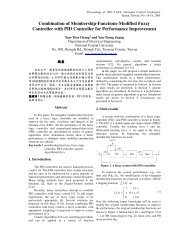
Proceedings of 2005 CACS Automatic Control ConferenceTainan, Taiwan, Nov 18-19, 2005table 1 for <strong>cost</strong> analysis). It consists of anATmega128 RISC CPU, an RS232 port tocommunicate <strong>with</strong> a PC, an in system programming(ISP) port for downloading programs from a PC to the128K byte flash memory, 6 pulse width modulation(PWM) output channels to drive power switches, 8A/D ports for accessing physical signals, an encoderinput port <strong>with</strong> resolutions being increased 4 times viaa programmable logic device (PLD), and several<strong>digital</strong> I/O ports. The reasons to choose an 8-bitmicroprocessor whose price is comparable to a <strong>digital</strong>signal processor (TMS320C24x) are threefold: 1)internal flash ROM size (128Kbyte) is larger, and canbe easily accessed via the ISP port; 2) softwaredeveloping environment can be constructed <strong>with</strong>outany additional <strong>cost</strong>, and 3) the undergraduate studentsare more familiar <strong>with</strong> 8-bit micro-<strong>control</strong>lers than<strong>digital</strong> signal processors (TMS320C24x). Thedrawback for this choice is that the computationalspeed is s<strong>low</strong>er for multiplication and division,although this does not create too much trouble in ourexperiments.To download programs into the microprocessorby using the ISP port of ATmega128, a simple andcheap hardware interface circuit connected to theprinter port of a PC is necessary(www.lancos.com/e2p/avrisp-stk200.gif). Thecorresponding software, PonyProg2000, which runs atthe PC side can also be freely downloaded from theweb page www.lancos.com/ppwin95.html. Theencoder input circuit which is capable of increasingthe resolution 4 times of the original signals comingfrom an encoder is shown in figure 2. The idea isfrom an application note [10] by Microchiptechnology, Inc., and the programming equations ofthe PLD are listed in the fol<strong>low</strong>ing table:Table 1: Programming equations of the PLD forresolution enhancementPLD programming equations;---------------------------------------MODULE ENCODEDECLARATIONSIA , IB ,CLK,Mode PIN 2,3,1,4;UP,DOWN,U_D,DIR PIN 16,17,15,14;S1 ,S3, S2, S4,X1 NODE;EQUATIONSS2 := S1;S4 := S3;S1 := IA;S3 := IB;UP =(!S1 & S2 & S3 & S4+S1 & S2 & S3 & !S4 & Mode+S1 & !S2 & !S3 & !S4 & Mode+!S1 & !S2 & !S3 & S4 & Mode );DOWN =(S1 & S2 & !S3 & S4 & Mode+!S1 & S2 & !S3 & !S4 & Mode+!S1 & !S2 & S3 & !S4+S1 & !S2 & S3 & S4 & Mode );U_D := UP + DOWN;X1:=DIR;DIR=(UP # X1) &!DOWN;ENDThe resolution enhancement circuit can not onlygenerate two separate 4 times resolution up and downcount signals, it can also give an up/down countingsignal and a direction signal to meet different needs.The entire hardware circuit is shown in figure 3.Sensor Circuits:Temperature orcurrent ...Download program via ISP 8 A/D portsPersonal computer:communication &<strong>control</strong>Figure 1.Figure 2.RS2322.2 Software moduleMicro‐<strong>control</strong>ler:AVR mega128downEncoder counter:PLD for resolutionenhancement (4x)up6 PWMchannelsPhysical variablesΦ 1Φ 2Driver Circuits:for Motor or RelayThe hardware configuration of the<strong>educational</strong> <strong>platform</strong>The encoder interface circuit that provides4 times resolutionThe programming language used in the<strong>educational</strong> <strong>platform</strong> is C, because of its portabilityand easy readability when compared <strong>with</strong> theassembly language.Thanks to the GNU project (www.gnu.org), theGNU C compiler for ATmega128 can be freelydownloaded from the web site www.avrfreaks.net, tohelp us construct the programming environment at no<strong>cost</strong>. The communication program shown in figure 4is written by using visual basic and provides functionsof loading <strong>control</strong> parameters into the microprocessor,receiving data of <strong>control</strong>led variables from themicroprocessor through the serial RS232 bus,graphical representation of data, and saving data asMATLAB m-file format. Sample software codes aregiven to students such that more sophisticated analysistools could be implemented on top of them.3. ExperimentsTwo basic <strong>control</strong> problems are devised to helpstudents turn <strong>digital</strong> <strong>control</strong> theories into workingalgorithms in the <strong>educational</strong> <strong>platform</strong>, such that all