Light Oil Burners RL 28/2 - Power Equipment Company
Light Oil Burners RL 28/2 - Power Equipment Company
Light Oil Burners RL 28/2 - Power Equipment Company
- No tags were found...

You also want an ePaper? Increase the reach of your titles
YUMPU automatically turns print PDFs into web optimized ePapers that Google loves.
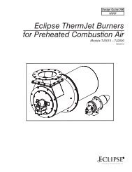
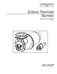
Installation, use and maintenance instructions<strong>Light</strong> <strong>Oil</strong> <strong>Burners</strong><strong>RL</strong> <strong>28</strong>/2 - 38/2 - 50/2Low - High OperationC6505050
CONTENTSWARNINGTECHNICAL DATA. . . . . . . . . . . . . . . . . . . . . . . . . . . . . .page 3Burner models . . . . . . . . . . . . . . . . . . . . . . . . . . . . . . . . . . . . . 3Accessories . . . . . . . . . . . . . . . . . . . . . . . . . . . . . . . . . . . . . . . 3Burner description . . . . . . . . . . . . . . . . . . . . . . . . . . . . . . . . . . 4Packaging - Weight. . . . . . . . . . . . . . . . . . . . . . . . . . . . . . . . . . 4Max. dimensions. . . . . . . . . . . . . . . . . . . . . . . . . . . . . . . . . . . . 4Standard equipment . . . . . . . . . . . . . . . . . . . . . . . . . . . . . . . . . 4Firing rate. . . . . . . . . . . . . . . . . . . . . . . . . . . . . . . . . . . . . . . . . 5INSTALLATION . . . . . . . . . . . . . . . . . . . . . . . . . . . . . . . . . . . . 6Boiler plate . . . . . . . . . . . . . . . . . . . . . . . . . . . . . . . . . . . . . . . . 6Blast tube length . . . . . . . . . . . . . . . . . . . . . . . . . . . . . . . . . . . 6Securing the burner to the boiler . . . . . . . . . . . . . . . . . . . . . . . 6Choice of nozzles for low and high fire . . . . . . . . . . . . . . . . . . . 6Nozzle assembly . . . . . . . . . . . . . . . . . . . . . . . . . . . . . . . . . . . 7Combustion head setting . . . . . . . . . . . . . . . . . . . . . . . . . . . . . 7Fuel supply. . . . . . . . . . . . . . . . . . . . . . . . . . . . . . . . . . . . . . . . 8Hydraulic connections . . . . . . . . . . . . . . . . . . . . . . . . . . . . . . . 8Pump . . . . . . . . . . . . . . . . . . . . . . . . . . . . . . . . . . . . . . . . . . . . 9Burner calibration . . . . . . . . . . . . . . . . . . . . . . . . . . . . . . . . . . 10Final check . . . . . . . . . . . . . . . . . . . . . . . . . . . . . . . . . . . . . . . 11Burner operation. . . . . . . . . . . . . . . . . . . . . . . . . . . . . . . . . . . 12Factory wiring diagram - burner mounted LAL control. . . . . . . 13Field wiring diagram- burner mounted LAL control . . . . . . . . . 14Factory wiring diagram - remote panel . . . . . . . . . . . . . . . . . . 15Appendix - Burner firing rates according to air density. . . . . . . . . .16Siemens LAL control sequence of operations . . . . . . . . . . . . . 17Siemens LAL control troubleshooting guide . . . . . . . . . . . . . . 18Start up report . . . . . . . . . . . . . . . . . . . . . . . . . . . . . . . . . . . . 19Do not store flammable or hazardous materials in the vicinityof fuel burning appliances.Improper installation, adjustment, alteration, service or maintenancecan cause property damage, personal injury ordeath. Refer to this manual for instructional or additional information.Consult a certified installer, service representativeor the gas supplier for further assistance.Burner shall be installed in accordance with manufacturersrequirements as outlined in this manual, local codes and authoritieshaving juristiction.N.B.Figures mentioned in the text are identified as follows:1)(A) = part 1 of figure A, same page as text;1)(A)p.4 = part 1 of figure A, page number 4.2
TECHNICAL DATAMODEL <strong>RL</strong> <strong>28</strong> <strong>RL</strong> 38 <strong>RL</strong> 38 <strong>RL</strong> 50Output (1)High fire MBtu/hr (3) 630 - 1260 896 - 1708 896 - 1708 1120 - 2240Delivery (1) GPH 4.5 - 9 6.4 - 12.2 6.4 - 12.2 8 - 16Low fire MBtu/hr (3) 364 - 630 448 - 896 448 - 896 560 - 1120GPH 2.6 - 4.5 3.2 - 6.4 3.2 - 6.4 4 - 8Fuel# 2 Fuel oilOperationLow - highNozzles number 2Standard applicationsHot water, steam, thermal oilAmbient temperature °F 32 - 104 (0 - 40 °C)Combustion air temperature °F max 140 (60 °C)Main power supply (+/- 10 %) V/Ph/Hz 120/1/60 208-230 / 460 / 575 / 3 / 60Fan motor(1) Reference conditions: Ambient temperature 68° F (20° C) - Barometric pressure 394” WC - Altitude 329 ft.(2) Sound pressure measured in manufacturers combustion laboratory, with burner operating on test boiler and at maximum rated output.(3) Equivalent Btu values based on 1 USGPH = 140,000 Btu/hr.Burner models designationsrpmW - HPVA3400370 - 0.51205.2Motor capacitor µF 45Ignition trasformerV1 - V2I1 - I2Pumpdelivery (174 PSI)GPHpressure rangePSI120 V - 2 x 5 kV3.7 A - 35 mA2260 - 2603400550 - 0.75208 - 230 / 460 / 5753.2 - 1.6 - 1.3Electrical power consumption W max 550 600 700 750Electrical protection NEMA 1Noise levels (2) dBA 68.0 70.0 70.0 75.0Model Code Voltage Flame safeguard<strong>RL</strong> <strong>28</strong>C9511200 (3473270)C9611200 (3473272)120/1/60120/1/60Burner mountedRemote panel<strong>RL</strong> 38C9512200 (3474170)C9612200 (3474172)C9512250 (3474370)C9512251 (3474370)C9612250 (3474372)C9612251 (3474372)120/1/60120/1/60208-230/460/3/60575/3/60208-230/460/3/60575/3/60Burner mountedRemote panelBurner mountedBurner mountedRemote panelRemote panel<strong>RL</strong> 50C9513200 (3474670)C9513201 (3474670)C9613200 (3474672)C9613201 (3474672)208-230/460/3/60575/3/60208-230/460/3/60575/3/60Burner mountedBurner mountedRemote panelRemote panelACCESSORIES (optional):• Kit for lengthening the combustion headL = Standard lengthL1 = Length obtainable with the kitCOD. 3010250 L = 81/2“ L1 = 1313/16“ • <strong>RL</strong> <strong>28</strong>COD. 3010251 L = 81/2“ L1 = 1313/16“ • <strong>RL</strong> 38COD. 3010252 L = 81/2“ L1 = 1313/16“ • <strong>RL</strong> 50Important:The installer is responsible for the supply and installation of any safety device(s) not indicated in this manual.3
(A)inch A B C lbs<strong>RL</strong> <strong>28</strong><strong>RL</strong> 38<strong>RL</strong> 50(B)D2278D22763931/32”3931/32”3931/32”2413/16”2413/16”2413/16”1911/16”1911/16”1911/16”808486D88BURNER DESCRIPTION (A)1 Ignition electrodes2 Combustion head3 Screw for combustion head adjustment4 Photocell for flame monitoring5 Screw for fixing fan to flange6 Slide bars for opening the burner and inspectingthe combustion head7 Hydraulic cylinder for regulation of the air damper inlow and high fire positions. When the burner is notoperating the air damper is fully closed in order toreduce heat dispersion from the boiler due to theflue draught which draws air from the fan suction inlet.8 Safety solenoid valve9 Pump10 Plate prearranged to drill 4 holes for the passage ofhoses and electrical cables.11 Air inlet to fan12 Fan pressure test point13 Boiler mounting flange14 Flame stability disk15 Flame inspection window16 Motor contactor17 Flame safeguard control18 Two switches:- one "burner off - on"- one for "low and high fire operation"19 Burner terminal strip20 Air damper21 Pump pressure adjustment22 Low and high fire valve assemblyTwo types of burner failure may occur:• FLAME SAFEGUARD LOCK-OUT:if the flame relay 17)(A) pushbutton lights up, it indicatesthat the burner is in lock-out.To reset, press the pushbutton.• MOTOR TRIP(<strong>RL</strong> 38 - <strong>RL</strong> 50 three phase):release by pressing the pushbutton on thermal overload.PACKAGING-WEIGHT (B)Approximate measurements• The burner is shipped in cardboard box with themaximum dimensions shown in table (B).• The weight of the burner complete with packaging isindicated in table (B).MAX. DIMENSIONS (C)Approximate measurementsThe maximum dimensions of the burners are given in(C).Inspection of the combustion head requires the burnerto be opened and the rear part withdrawn on the slidebars.The maximum dimension of the burner, without casing,when open is give by measurement H.(C)D452STANDARD EQUIPMENT2 - Flexible hoses1 - Burner head gasket4 - Screws to secure the burner flange to the boiler:3/8 W x 1”1 - Instruction booklet1 - Spare parts list1 - Adaptor G 1/8” - 1/8” NPT<strong>RL</strong> A B C D (1) E F G H (1)<strong>28</strong> 1823/32” 1821/32” 1813/32” 81/2” - 1313/16” 51/2” 1327/32” 21/16” 2615/32” - 313/4”38 1823/32” 1821/32” 1813/32” 81/2” - 1313/16” 51/2” 1327/32” 21/16” 2615/32” - 313/4”50 1823/32” 1821/32” 1813/32” 81/2” - 1313/16” 531/32” 1327/32” 21/16” 2615/32” - 313/4”4
Comb. chamb. “ WC Comb. chamb. “ WCL Comb. chamb. “ WCFIRING RATE (A)The <strong>RL</strong> <strong>28</strong> - 38 - 50 Model burners are available inlow-high firing configuration.LOW FIRE DELIVERY must be selected within area Aof the adjacent diagrams.HIGH FIRE DELIVERY must be selected within area B.This area provides the maximum delivery of the burnerin relation to the pressure in the combustion chamber.The firing rate may be found by plotting a vertical linefrom the desired delivery and a horizontal line fromthe pressure in the combustion chamber. The intersectionof these two lines is the firing rate which mustlie within area B.Important:the FIRING RATE area values have been obtainedconsidering a surrounding temperature of 68 °F (20°C), and an atmospheric pressure of 394” WC abovesea level and with the combustion head adjusted asshown on page 7.Note:The FIRING RATE areas given in figure (A) have beenreduced by 10% with respect to the maximum range thatcan be reached.Consult Appendix on page 16 for operation at differentsurrounding temperatures and/or altitudes.MINIMUM FURNACE DIMENSIONS (B)The firing rates were set in relation to certified test boilers.Figure (B) indicates the diameter and length of the testcombustion chamber.Example:output 1388 MBtu/hr:diameter 20 inch - length 4.9 ft.(A)D2279Diameter (inches)Recommended furnace dimensionsLength (ft)(B)D29185
inch A B C<strong>RL</strong> <strong>28</strong> 65/16“ 813/16“ 3/8 W<strong>RL</strong> 38 65/16“ 813/16“ 3/8 W<strong>RL</strong> 50 65/16“ 813/16“ 3/8 W(A)D455INSTALLATIONBOILER PLATE (A)Drill the combustion chamber mounting plate asshown in (A). The position of the threaded holes canbe marked using the burner gasket supplied with theburner.BLAST TUBE LENGTH (B)The length of the blast tube must be selected accordingto the indications provided by the manufacturer ofthe boiler, and it must be greater than the thickness ofthe boiler door complete with its insulation. The rangeof lengths available, L (inch), is as follows:Blast tube 7): <strong>RL</strong> <strong>28</strong> <strong>RL</strong> 38 <strong>RL</strong> 50• short 81/2“ 81/2“ 81/2“• long (with the kit) 1313/16“ 1313/16“ 1313/16“For boilers with front flue passes 10) or flame inversionchambers, protective insulation material 8) must be insertedbetween the boiler's refractory 9) and the blasttube 7).This protective insulation must not compromise the extractionof the blast tube.For boilers having a water-cooled front, the insulation8)-9)(B) is not required unless it is required by theboiler manufacturer.D2<strong>28</strong>0SECURING THE BURNER TO THE BOILER (B)Disassemble the blast tube 7) from the burner 4) byproceeding as follows:- Remove the screws 2) from the two slide bars 3).- Remove the screw 1) fixing the burner 4) to theflange 5).- Withdraw the blast tube 7) complete with flange 5)and slide bars 3).Secure flange 5)(B) to the boiler plate inserting thesupplied gasket 6). Use the 4 screws provided afterhaving protected the thread with an anti-seize product(high-temperature grease, compounds, graphite).The burner-boiler seal must be airtight.(B)<strong>RL</strong> <strong>28</strong><strong>RL</strong> 38<strong>RL</strong> 50(C)60°Nozzlesize2.002.252.503.003.502.503.003.504.004.505.003.003.504.004.505.005.506.00GPH145 PSI 174 PSI 203 PSI2.472.753.073.684.323.073.684.324.935.546.153.684.324.935.546.156.757.402.723.043.394.074.743.394.074.745.446.126.794.074.745.446.126.797.468.172.953.333.684.425.163.684.425.165.896.637.364.425.165.896.637.368.108.87MBtu/hr174 PSI3814<strong>28</strong>47557066447557066476<strong>28</strong>5795157066476<strong>28</strong>5795110441144D339CHOICE OF NOZZLES FOR 1st AND 2nd STAGEBoth nozzles must be chosen from among those listedin Table (C).The first nozzle determines the delivery of the burnerat low fire.The second nozzle works in combination with the lowfire nozzle to determine the delivery of the burner athigh fire.The total deliveries of the low and high fire nozzlesmust be contained within the value range indicated onpage 3.Use nozzles with a 60° spray angle at the recommendedpressure of 174 PSI.The two nozzles usually have equal deliveries, but thelow fire nozzle may have the following specifications ifrequired:• a delivery less than 50% of the total delivery wheneverthe back-pressure peak must be reduced atthe moment of firing;• a delivery higher than 50% of the total deliverywhenever the combustion during low fire must beimproved.6
D2<strong>28</strong>1Example with the <strong>RL</strong> 38 ModelBoiler output = 912 MBTU/hr - efficiency 80 %Output required by the burner =912 / 0.8 = 1140 MBTU/hr1140 / 2 = 570 MBTU/hr per nozzletherefore, two equal, 60°, 174 PSI nozzles arerequired:1° = 3.00 GPH with 2° = 3.00 GPH,or the following two different nozzles:1° = 3.50 GPH with 2° = 2.50 GPH,or:1° = 2.50 GPH with 2° = 3.50 GPH.(A)D458D460(B)NOZZLE ASSEMBLYAt this stage of installation the burner is still disassembledfrom the blast tube; it is now possible to fit twonozzles, after having removed the plastic plugs 2)(A),inserting the wrench through the central hole in theflame stability disk. Do not use any sealing productssuch as gaskets, sealing compound, or tape. Be carefulto avoid damaging the nozzle sealing seat. Thenozzles must be screwed into place tightly but carefully.The nozzle for the low fire of operation is the one lyingbeneath the firing electrodes Fig. (B).Make sure that the electrodes are positioned as shownin Figure (B).Finally remount the burner 4)(C) to the slide bars 3)and slide it up to the flange 5), keeping it slightly raisedto prevent the flame stability disk from pressingagainst the blast tube.Tighten the screws 2) on the slide bars 3) and screw1) that attaches the burner to the flange.If it proves necessary to change a nozzle with theburner already fitted to the boiler, proceed as outlinedbelow:- Retract the burner on its slide bars as shown in fig.(B)p.6.- Remove the nuts 1)(D) and the disk 2).- Use wrench 3)(D) to change the nozzles.(C)(D)SETTING THE COMBUSTION HEADD461COMBUSTION HEAD SETTINGThe setting of the combustion head depends exclusivelyon the delivery of the burner at high fire - inother words, the combined delivery of the two nozzlesselected on page 6. Turn screw 4)(E) until the notchshown in diagram (F) is level with the front surface offlange 5)(E).(E)D462Example:The <strong>RL</strong> 38 Model with two 3.00 GPH nozzles and174 PSI pump pressure.Find the delivery of the two 3.00 GPH nozzles in table(C), page 6:4 + 4 = 8 GPH.Diagram (F) indicates that for a delivery of 8 GPH the<strong>RL</strong> 38 Model requires the combustion head to be setto approx. three notches, as shown in Figure (E).N° NotchesD2<strong>28</strong>2(F)Fuel oil delivery at high fireUSGPH7
HYDRAULIC SYSTEMFUEL SUPPLYDOUBLE - PIPE SYSTEM (A)The burner is equipped with a self-priming pumpwhich is capable of feeding itself within the limitslisted in the table at the left.The tank higher than the burner AThe distance "P" must not exceed 33 ft in order toavoid subjecting the pump's seal to excessive strain;the distance "V" must not exceed 13 ft in order to permitpump self-priming even when the tank is almostcompletely empty.The tank lower than the burner BPump suction values higher than 6.5 PSI must not beexceeded because at higher levels gas is releasedfrom the fuel, the pump starts making noise and itsworking life-span decreases.It is good practice to ensure that the return and suctionlines enter the burner from the same height; inthis way it will be more improbable that the suctionline fails to prime or stops priming.LOOP CIRCUITA loop circuit consists of a loop of piping suppliedfrom and returning to the tank with an auxiliary pumpthat circulates the fuel under pressure. A branch connectionfrom the loop goes to feed the burner. Thiscircuit is extremely useful whenever the burner pumpdoes not succeed in self-priming because the tankdistance and/or height difference are higher than thevalues listed in the table.KeyH = Pump/Foot valve height differenceL = Piping lengthØ = Inside pipe diameter1 = Burner2 = Pump3 = Filter4 = Manual on/off valve5 = Suction line6 = Foot valve7 = Return line667 5315/16”4- H + H VP57AB31D2<strong>28</strong>32+ H- HL (ft)Ø (inch)(ft)5/16” 3/8” 1/2”+ 13 115 296 500+ 10 99 263 500+ 6.6 86 227 500+ 3.3 69 194 4<strong>28</strong>+ 1.6 63 174 3910 56 158 355- 1.6 49 141 319- 3.3 43 122 <strong>28</strong>3- 6.6 30 89 211- 10 13 53 138- 13 – 20 66(A)HYDRAULIC CONNECTIONSHYDRAULIC CONNECTIONS (B)The pumps is equipped with a by-pass that connectsreturn line and suction line. It is factory set with theby-pass valve closed by screw 6)(A)p.12.It is therefore necessary to connect both hoses to thepump.The pump seal will be damaged immediately if it isrun with the return line closed and the by-passscrew inserted.Remove the plugs from the suction and return connectionsof the pump.Insert the hose connectors into the connections andscrew them down.Take care that the hoses are not stretched or twistedduring installation.Route the hoses through the holes in the plate, preferablyusing those on the rh side, fig. (B): unscrew thescrews 1), now divide the insert piece into its twoparts 2) and 3) and remove the thin section blockingthe two passages 4).Install the hoses where they cannot be stepped on orcome into contact with hot surfaces of the boiler.D2<strong>28</strong>4(B)8
D2<strong>28</strong>6PUMP (A)1 - Suction 1/4” NPT2 - Return 1/4” NPT3 - Pressure gauge attachment G 1/84 - Vacuum gauge attachment G 1/85 - Pressure adjustment screwA - Min. delivery rate at 174 PSI pressureB - Delivery pressure rangeC - Max. suction pressureD - Viscosity rangeE - Fuel oil max. temperatureF - Max. suction and return pressureG - Pressure calibration in the factoryH - Filter mesh width(A)ABCDEFGHPUMPGPHPSIPSIcSt°F - °CPSIPSIinchAL 65 C21.558 - 2616.52 - 12140 - 60291740.006PUMP PRIMING- Before starting the burner, make sure that thetank return line is not clogged. Obstructions inthe line could cause the seal located on thepump shaft to break. (The pump leaves the factorywith the by-pass closed).- In order for self-priming to take place, one of thescrews 3)(A) of the pump must be loosened in orderto bleed off the air contained in the suction line.- Start the burner by closing the control circuit andwith switch 1)(B)p.10 in the "ON" position. The pumpmust rotate in the direction of the arrow marked onthe cover.- The pump can be considered to be primed when thefuel oil starts coming out of the screw 3). Stop theburner: switch 1)(B)p.10 set to "OFF" and tighten thescrew 3).The time required for this operation depends upon thediameter and length of the suction tubing. If the pumpfails to prime at the first starting of the burner and theburner locks out, wait approx. 15 seconds, reset theburner, and then repeat the starting operation as oftenas required. After 5 or 6 starting operations allow 2 or3 minutes for the transformer to cool.Do not illuminate the photocell or the burner will lockout; the burner should lock out anyway about 10 secondsafter it starts.Important:the priming operation is possible because the pump isalready full of fuel when it leaves the factory. If thepump has been drained, fill it with fuel through theopening on the vacuum gauge connection prior tostarting; otherwise, the pump will seize. Whenever thelength of the suction piping exceeds 66 - 99 ft, thesupply line must be filled using a separate pump.9
BURNER CALIBRATIONFIRINGSet switch 1)(B) to "ON".During the first firing, during the switch over from lowto high fire, there is a momentary lowering of the fuelpressure caused by the filling of the high fire nozzletubing. This lowering of the fuel pressure can causethe burner to lock-out and can sometimes give rise topulsations.Once the following adjustments have been made, thefiring of the burner must generate a noise similar tothe noise generated during operation.(A)(B)Low fire(C)High fireBurnerOffNozzlesizeGPH2.002.252.503.003.50NozzlesizeGPH4.505.105.806.407.007.708.309.001 2Stage1°On 2°<strong>RL</strong> <strong>28</strong> <strong>RL</strong> 38 <strong>RL</strong> 50α°1417202224NozzlesizeGPH2.503.003.504.004.505.00α°121820222326NozzlesizeGPH3.003.504.004.505.005.506.00<strong>RL</strong> <strong>28</strong> <strong>RL</strong> 38 <strong>RL</strong> 50“WC2.402.502.602.702.803.003.303.50NozzlesizeGPH6.407.007.708.309.3010.2011.2012.10“WC2.702.702.702.702.702.703.103.70D469NozzlesizeGPH8.009.3010.6011.8013.1014.4016.0016.00“WC = air pressure in 1) with zero pressure in 2)α°121518212327<strong>28</strong>“WC2.402.402.502.602.603.004.003.60D468OPERATIONThe optimum calibration of the burner requires ananalysis of the flue gases at the boiler outlet andadjustments on the following points.• Low and high fire nozzlesSee the information listed on page 6.• Combustion headThe adjustment of the combustion head alreadycarried out need not be altered unless the high firedelivery of the burner is changed.• Pump pressure174 PSI: This is the pressure calibrated in the factorywhich is usually sufficient for most purposes. Sometimes,this pressure must be adjusted to:145 PSI in order to reduce fuel delivery. This adjustmentis possible only if the ambient temperature remainsabove 0°C;203 PSI in order to increase fuel delivery or to ensurefirings even at temperatures of less than 0°C.In order to adjust pump pressure, use the relevantscrew 5)(A) page 9.• Low fire air damperKeep the burner operating at low fire by setting theswitch 2)(B) to the low fire. Opening of the airdamper 1)(A) must be adjusted in proportion to theselected nozzle: the index 7)(A) must be alignedwith the rate specified in table (C). This adjustmentis achieved by turning the hex element 4)(A):- in rh direction (- sign) the opening is reduced;- in lh direction (+ sign) the opening increases.Example <strong>RL</strong> 38 - low fire nozzle 3.00 GPH:18° notch aligned with index 7(A).When the adjustment is done lock the hex element4) with the ring nut 3).• High fire air damperSet switch 2)(B) to the high fire position and adjustthe air damper 1)(A) by turning the hex element6)(A), after having loosened the ring nut 5)(A).Air pressure at attachment 1)(D) must be approximatelythe same as the pressure specified in table(D) plus the combustion chamber pressure measuredat attachment 2). Refer to the example in theadjacent figure.NOTE:in order to facilitate adjustment of hex elements 4)and 6)(A), use a 1/8” Allen key 8)(A).D2<strong>28</strong>7(D)10
D482FINAL CHECKS• Obscure the photocell and switch on the burner: theburner should start and then lock-out about 5 s afteropening of the low fire nozzle valve.• Illuminate the photocell and reset the burner: the burnershould go into lock-out .• Obscure the photocell while the burner is in high fireoperation, the following must occur in sequence: flameextinguished within 1 s, pre-purging for about 20 s,sparking for about 5 s, burner goes into lock-out.• Switch off operating control while the burner is running:the burner should stop.(A)(B)(D)(E)D483XdimensionD484(C)D486D<strong>28</strong>54MAINTENANCECombustionAn analysis ot the flue gases at the boiler outlet isrequired. Significant differences with respect to the previousmeasurements indicate the points where morecare should be exercised during maintenance.PumpThe pump delivery pressure must be stable at 174 PSI.The suction must be less than 6.5 PSI.Unusual noise must not be evident during pump operation.If the pressure is found to be unstable or if the pumpruns noisily, the flexible hose must be detached from theline filter and the fuel must be sucked from a tanklocated near the burner. This measure permits thecause of the anomaly to be traced to either the suctionline or the pump.If the problem lies in the suction line, check to makesure that the filter is clean and that air is not enteringthe piping.Filters (A)Check the following filters:• on line 1) • at nozzle 3), pump 2) and clean or replaceas required.If rust or other impurities are observed inside the pump,use a separate pump to suck out any water and otherimpurities that may have deposited on the bottom of thetank.FanCheck to make sure that no dust has accumulatedinside the fan or on its blades, as this condition willcause a reduction in the air flow rate and create incompletecombustion.Combustion headCheck to make sure that all the parts of the combustionhead are in good condition, positioned correctly, free ofall impurities, and that no deformation has been causedby operation at high temperatures.NozzlesDo not clean the nozzle orifices.Replace the nozzles every 2-3 years or whenever necessary.Combustion must be checked after the nozzleshave been changed.Photocell (cad cell) (B)Clean the glass cover from any dust that may haveaccumulated. Photocell 1) can be removed by pulling itoutward forcefully.Flame inspection window (C)Clean the glass.Flexible hosesCheck to make sure that the flexible hoses are still ingood condition.BoilerClean the boiler as indicated in its accompanyinginstructions in order to maintain all the original combustioncharacteristics intact, especially the flue gas temperatureand combustion chamber pressure. Lastly,check the condition of the flue gas stack.TO OPEN THE BURNER (D)- Switch off the electrical power.- Loosen screws 1) and withdraw the cover 2).- Unscrew screws 3).- Fit the two extensions 4) supplied with the burner ontothe slide bars 5) (model with long blast tube, obtainablewith the kit).- Pull part A backward keeping it slightly raised to avoiddamaging the disk 6) on blast tube 7).FUEL PUMP AND/OR COUPLINGS REPLACEMENT (E)See fig. (E). Dimension X should be set as follows:<strong>RL</strong><strong>28</strong> - 1 /4“<strong>RL</strong>38 - 5 /32“<strong>RL</strong>50 - 5 /32“11
BURNER OPERATIONBURNER STARTING (A)Operating control closes.The motor starts and the ignition transformer is connected.The pump 3) sucks the fuel from the tank through thepiping 1) and the filter 2) and pumps it under pressurefor delivery. The piston 4) rises and the fuel returns tothe tank through the piping 5) - 7). The screw 6) closesthe by-pass to the suction side of the pump and the solenoidvalves 8) - 11) - 16), de-energized, close theflow to the nozzles.The hydraulic cylinder 15), piston A, opens the airdamper: pre-purging begins with the low fire air delivery.At the opening of the solenoid valves 8) and 16) thefuel passes through the piping 9) and filter 10) and isthen sprayed out through the nozzle, igniting when itcomes into contact with the spark. This is the low fireflame.If the high fire control device is closed, the solenoidvalve 11) is opened and the fuel enters the valve 12)and raises the piston which opens two passages: oneto piping 13), filter 14), and the high fire nozzle, andthe other to the cylinder 15), piston B, that opens thefan air damper for high fire.FIRING FAILUREIf the burner does not fire, it goes into lock-out within5 s of the opening of the low fire solenoid valve.The flame safeguard indicator light will light up.LOCKOUT DURING OPERATIONIf the flame goes out during operation, the burner shutsdown automatically within 1 second and automaticallyattempts to start again by repeating the starting cycle.(A)D2<strong>28</strong>812
Factory Wiring Diagram<strong>RL</strong> <strong>28</strong> - 38 single phase with burner mounted Siemens LAL controlContinuous fan operationChange the wire connection from terminal 6 to terminal 1of control box.D2248D<strong>28</strong>56(A)<strong>RL</strong> 38 - 50 three phase with burner mounted Siemens LAL controlContinuous fan operationChange the wire connection from terminal 6 to terminal 1of control box.D2249D<strong>28</strong>57(B)LAYOUT (A)<strong>Burners</strong> <strong>RL</strong> <strong>28</strong> (single-phase)The flame safeguard mounted on the burner.LAYOUT (B)<strong>Burners</strong> <strong>RL</strong> 38-50 (three-phase)The flame safeguard mounted on the burner.• Models <strong>RL</strong> 38 - <strong>RL</strong> 50 three phase leave the factory preset for208-230 V power supply.• If 460 V power supply is used, change the motor connectionfrom delta to star and change the setting of the thermal cut-outas well.Key to Layouts (A) - (B)C - CapacitorCMV - Motor contactorDA - Control boxMB - Burner terminal stripFR - PhotocellI1 - Switch: burner off - onI2 - Switch: low and high fire operationMV - Fan motorTA - Ignition transformerTB - Burner ground (earth) connectionV1 - Low fire solenoid valveV2 - High fire solenoid valveVS - Safety solenoid valveRT - Thermal overload13
Field Wiring Diagram<strong>RL</strong> <strong>28</strong> - 38 single-phase burner with burner mounted LAL flame safeguard(A)D2251<strong>RL</strong> 38 - 50 three-phase burner with burner mounted LAL flame safeguard<strong>RL</strong> 38 three-phase - <strong>RL</strong> 50208/230 V 460 V 575 VF A T6 T6 T4S AWG 14 14 14(A)D2252FIELD WIRING CONNECTIONSAs set by installerUse flexible cables according to local regulation.LAYOUT (A)The <strong>RL</strong> <strong>28</strong> - 38 Models field connections single-phase 120 Vpower supply.LAYOUT (B)The <strong>RL</strong> 38 - 50 Models field connections three-phase 208-230/460 V power supply.Key to wiring layouts (A) - (B)MB - Burner terminal stripPS - Remote lock-out resetH1 - Remote lock-out signalH2 - Low fire signalH3 - High fire signalH4 - <strong>Power</strong> on signalH5 - Limit satisfiedIN - Manual burner stop switchOC - Operating control.OC2 - High-low control.HL - High limit control.14Important:The burner is factory set for low - high operation and it must beconnected to the OC2 control device to control fuel oil valve V2.If on - off operation is required, instead of control device OC2install a jumper lead between terminals T6 and T8 of burner terminalstrip.NOTE• The setting of the thermal overload must be according to the totalburner amperage draw.• <strong>Burners</strong> <strong>RL</strong> 38 three-phase and <strong>RL</strong> 50 leave the factory presetfor 208-230 V power supply. If 460 V power supply is used,change the motor connection from delta to star and change thesetting of the thermal overload.• The <strong>RL</strong> <strong>28</strong> - 38 - 50 burners have been type-approved for intermittentoperation. This means they should compulsorily bestopped at least once every 24 hours to enable the control boxto perform self checks at start-up. Burner halts are normally providedfor automatically by the boiler load control system.
Factory Wiring Diagram<strong>RL</strong> <strong>28</strong> - 38 single phase with remote control panelD2356(A)<strong>RL</strong> 38 - 50 single phase with remote control panel(B)D2357LAYOUT (A)<strong>Burners</strong> <strong>RL</strong> <strong>28</strong>-38 (single-phase)See the internal electrical systems of the remote panel in order tohave the complete wiring diagram.LAYOUT (B)<strong>Burners</strong> <strong>RL</strong> 38-50 (three-phase)For remote panel configurationsSee the internal electrical systems of the remote panel in order tohave the complete wiring diagram.Key to Layouts (A) - (B)C - CapacitorCMV - Motor contactorDA - Control boxMB - Burner terminal stripFR - PhotocellI1 - Switch: burner off - onI2 - Switch: low and high fire operationMV - Fan motorTA - Ignition transformerTB - Burner ground (earth) connectionV1 - Low fire solenoid valveV2 - High fire solenoid valveVS - Safety solenoid valveRT - Thermal overload15
APPENDIX - Burner firing rates according to air densityabove sea levelaverage barom.pressureCORRECTION FACTOR FAir temperature°F (°C)ft m “ W.C. mbar 0 (0°C) 41 (5°C) 50 (10°C) 59 (15°C) 68 (20°C) 77 (25°C) 86 (30°C) 104 (40°F)03296589871316164519742303263229613290394746055263592165790100200300400500600700800900100012001400160018002000399394389385380376372367363358354346337329321313101310009899789669559449329219108988788568368157941,0871,0731,0611,0501,0371,0251,0131,0000,9880,9770,9640,9420,9190,8970,8750,8521,0681,0541,0421,0311,0181,0070,9950,9820,9710,9590,9460,9250,9020,8810,8590,8371,0491,0351,0241,0131,0000,9890,9770,9650,9540,9420,9300,9090,8860,8660,8440,8221,0311,0171,0060,9950,9830,9720,9600,9480,9370,9260,9140,8930,8710,8510,8290,8081,0131,0000,9890,9780,9660,9550,9440,9320,9210,9100,8980,8780,8560,8360,8150,7940,9960,9830,9720,9620,9500,9390,9<strong>28</strong>0,9160,9060,8950,8830,8630,8420,8220,8010,7810,9800,9670,9560,9460,9340,9230,9130,9010,8910,8800,8680,8490,8<strong>28</strong>0,8080,7880,7680,9480,9360,9260,9160,9040,8940,8840,8720,8620,8520,8410,8220,8010,7830,7630,743(A)The FIRING RATE area values have been obtained considering a surroundingtemperature of 68°F (20°C), and an atmospheric pressure of 398” W.C.and with the combustion head adjusted as shown on page 7.The burner may be required to operate with combustion air at a higher temperatureand/or at higher altitudes.Heating of air and increase in altitude produce the same effect: the expansionof the air volume, i.e. the reduction of air density.The burner fan's delivery remains substantially the same, but the oxygencontent per cubic meter and the fan's head are reduced.It is therefore important to know if the maximum output required of the burnerat a given combustion chamber pressure remains within the burner's firing rate range even at different temperature and altitude conditions.Proceed as follows to check the above:“ W.C.1 -Find the correction factor F in the Table (A) for the plant's air temperature and altitude.2 -Divide the burner's delivery Q by F in order to obtain the equivalent delivery Qe:H2H3H1D2617QeAMBTU/h(B)Qe = Q : F(MBtu/hr)3 -In the firing rate range of the burner, Fig. (B), indicate the work point defined by:Qe = equivalent deliveryH1 = combustion chamber pressureThe resulting point A must remain within the firing rate range.4 -Plot a vertical line from Point A as shown in Figure (B) and find the maximum pressure H2 of the firing rate.5 -Multiply H2 by F to obtain the maximum reduced pressure H3 of the firing rate.H3 = H2 x F(“ W.C.)If H3 is greater than H1, as shown in Fig. (B), the burner delivers the output required.If H3 is lower than H1, the burner's delivery must be reduced. A reduction in delivery is accompanied by a reduction of the pressure inthe combustion chamber:Qr = reduced deliveryH1r = reduced pressureH1r = H1 x (Qr)2QExample, a 5% delivery reduction:Qr = Q x 0.95H1r = H1 x (0.95) 2Steps 2 - 5 must now be repeated using the new Qr and H1r values.Important: the combustion head must be adjusted in respect to the equivalent delivery Qe.16
Low-HighOPERATION LAYOUTSwitching times are given in seconds, in the burnerstartup sequence.LAL 2.25t1t2t3t4184212t5t6t7t8optionaloptional124Legend for the timest1 Pre-purge time with air damper open.t2 Safety time.t3 Pre-ignition time, short (“Z” connected toterminal “16”).t4 Interval between voltage at terminals “18” and “20”t5 Air damper running time to OPEN position.t6 Air damper running time to low-flame position(MIN).t7 Permissible after-burn time.t8 Interval to the OPEN command for the air damper.D2275(A)17
BURNER FAULT INDICATIONSControl program fault conditions and lock-out indicationWhenever a fault occurs, the sequence switch stops and with it the lock-out indicator.The symbol above the reading mark of the indicator gives the type of fault:No start One of the contacts has not closed The contact of the limit thermostat or any other switchingdevices in the control loop of terminal 4 to terminal 5 areopened.Extraneous lightLock-out during or after completion of the control programExamples:– Flame not extinguished– Leaking fuel valves– Faulty flame supervision circuitInterruption of startup sequenceTerminals 6, 7 and 15 remain under voltage until fault has been corrected1Lock-outInterruption of startup sequenceLock-outLock-outDefect in the flame supervision circuit, faulty flame signal,extraneous lightTerminals 6, 7 and 15 remain under voltage until fault hasbeen correctedNo flame signal is present on completion of the safety timeFlame signal has been lost during operation18
BURNER START UP REPORTModel number:Project name:Installing contractor:Serial number:Start-up date:Phone number:GAS OPERATIONGas Supply Pressure:Main <strong>Power</strong> Supply:Control <strong>Power</strong> Supply:Burner Firing Rate:Manifold Pressure:Pilot Flame Signal:Low Fire Flame Signal:High Fire Flame Signal:CO 2 : Low FireO 2 : Low FireCO: Low FireNO X : Low FireNet Stack Temp - Low Fire:Comb. Efficiency - Low Fire:Overfire Draft:High FireHigh FireHigh FireHigh FireHigh Fire:High Fire:OIL OPERATION<strong>Oil</strong> supply pressure:<strong>Oil</strong> suction pressure:Control <strong>Power</strong> Supply:Burner Firing Rate:Low Fire Flame Signal:High Fire Flame Signal:Low Fire Nozzle Size:High Fire Nozzle Size:CO 2 : Low FireO 2 : Low FireCO: Low FireNO X : Low FireNet Stack Temp - Low Fire:Comb. Efficiency - Low Fire:Overfire Draft:Smoke number:High FireHigh FireHigh FireHigh FireHigh Fire:High Fire:CONTROL SETTINGSOperating Setpoint:High Limit Setpoint:Low Gas Pressure:High Gas Pressure:Low <strong>Oil</strong> Pressure:High <strong>Oil</strong> Pressure:Flame Safeguard Model Number:Modulating Signal Type:NOTES19
Represented By:<strong>Power</strong> <strong>Equipment</strong> <strong>Company</strong>2011 Williamsburg RoadRichmond, VA 23231Ph: 804-236-3800Fx: 804-236-3882www.peconet.com