160-80-40m End Fed Antenna G0CSK iss 1.1.pdf - arkansas ares ...
160-80-40m End Fed Antenna G0CSK iss 1.1.pdf - arkansas ares ...
160-80-40m End Fed Antenna G0CSK iss 1.1.pdf - arkansas ares ...
- No tags were found...

Create successful ePaper yourself
Turn your PDF publications into a flip-book with our unique Google optimized e-Paper software.
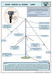
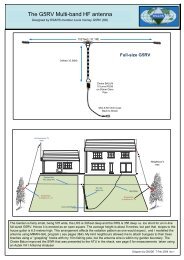
END FED INVERTED “L” ANTENNAFOR <strong>160</strong> – <strong>80</strong> – 40 METRESInsulatorInsulator<strong>40m</strong>Trap6.55m<strong>80</strong>mTrap8.54m9.9mMastHeight NotCriticalJunctionBoxGroundSpikeCoax CableNOTES:-nNOTES:-1.1.AtAtthetheJunctionJunctionBoxBox, coax, coaxinnerinnerconnectsconnecttotothetheantennaantennawirewire(blue)(blue)andandbraidbraidconnectsconnectedtotothethebrownbrownwirewireandtogroundthe groundspike.2.spike.Each section of the antenna is initially cut over size by 300mm, and trimmed to reduce the SWR on each band starting with2.<strong>40m</strong>Thebandthreesectionwiresfirstthat,makethen theup the<strong>80</strong>mendsection,fed antennaand finallyaretheinitially<strong>160</strong>mcutsectionover size by 300mm, and cut to reduce the SWR.3.3.If theIf thegroundgroundisisnotnotveryveryconductiveconductiveaddaddsupplementarysupplementaryradialradialinsulatedinsulatedwireswiresononthethegroundgroundtotoactactasasa counterpoise.a counterpoise.( 8(x84m)x 4m)4. To Tune the antenna Start with the <strong>40m</strong> section, then adjust the <strong>80</strong>m section, finally tune the 1<strong>80</strong>m section.Soldered<strong>Antenna</strong>wireCoax Cable – RG58Hole inDrain PipeCoax Braid2.5mm DiaCopper wireFixing pointG8ODETRAP DESIGN INFORMATION<strong>80</strong>m Trap 23 turns RG58 on <strong>40m</strong>m Diameter plastic pipe 150mm long<strong>80</strong>m Trap 23 turns RG58 on <strong>40m</strong>m Diameter plastic pipe 150mm long<strong>40m</strong> Trap 11 turns RG58 on <strong>40m</strong>m Diameter plastic pipe <strong>80</strong>mm long<strong>40m</strong> Trap 11 turns RG58 on <strong>40m</strong>m Diameter plastic pipe <strong>80</strong>mm long<strong>G0CSK</strong> EA5AVLN.B. A very useful tool for coax-traps is a program by Tony VE6YP called"coaxtrap.exe". You can download the program from his website www.qsl.net/ve6yp .G8ODE OCT 2008 <strong>iss</strong> 1.1
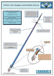
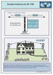
END FED INVERTED “L” ANTENNAFOR <strong>160</strong> – <strong>80</strong> – 40 METRESSoldered<strong>Antenna</strong>wireCoax Cable – RG58Hole inDrain Pipe<strong>80</strong>m Trap 23 Turns RG58<strong>40m</strong> Trap 11 Turn RG58On a <strong>40m</strong>m Dia formerCoax Braid2.5mm DiaCopper wireFixing pointG8ODEHere are the photographs two that were made using this form of construction. TheCoax has been taped over for additional protection, and the ends have been sealed byfirst fitting cut plastic discs and sealing these in with silicone bath sealern40 Metre Coaxial Trap<strong>80</strong> Metre Coaxial TrapN.B.<strong>G0CSK</strong> EA5AVLA very useful tool for coax-traps is a program by Tony VE6YP called "coaxtrap.exe". You candownload the program from his website www.qsl.net/ve6yp .G8ODE OCT 2008 <strong>iss</strong> 1.1
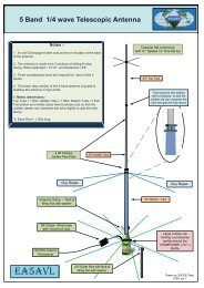
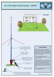
END FED INVERTED “L” ANTENNAFOR <strong>160</strong> – <strong>80</strong> – 40 METRES1.91MHz PlotsNote: The Red & Blue colours are used simply to emphasisethe vertical & horizontal components of the antenna current.The “X” marks the position of the traps.3.55MHz PlotsLooking at the current distribution, it will be seen that the1.92MHz Frequency does not cause either of the two traps tobecome activated & the antenna behaves as a long wire.n7.05 MHz PlotsHere the 3.55MHz frequency causes the <strong>80</strong>m trap to operateand electrically shorten the antenna. The current in the lastsection of the antenna is significantly reduced<strong>G0CSK</strong> EA5AVLHere the 7.05 MHz frequency causes the <strong>40m</strong> trap to operateand further electrically shorten the antenna. The current inthe last two sections is thus significantly reducedG8ODE OCT 2008 <strong>iss</strong>1.1
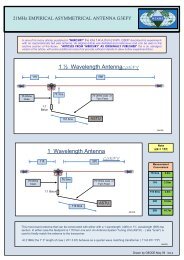
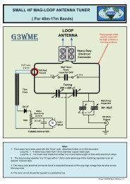
END FED INVERTED “L” ANTENNAFOR <strong>160</strong> – <strong>80</strong> – 40 METRES3-D Far Field Total Radiation Plot for 7.05 MHz.The 3.55Mhz &1.92MHz plots are very similar. The “funnel” in the centre gradually disappears. In all three cases themaximum radiation is at an angle of about 30 degrees to the ground.(see results below)MMANA-GAL MODEL RESULTSn<strong>G0CSK</strong> EA5AVLThe model only provides an indication of the expected performance of this antenna.In practice better SWR results & hence improved efficiencies can be obtained.G8ODE OCT 2008 <strong>iss</strong> 1.1