Robinair 34800-2K R-12/134a Recovery Unit - NY Tech Supply
Robinair 34800-2K R-12/134a Recovery Unit - NY Tech Supply
Robinair 34800-2K R-12/134a Recovery Unit - NY Tech Supply

You also want an ePaper? Increase the reach of your titles
YUMPU automatically turns print PDFs into web optimized ePapers that Google loves.
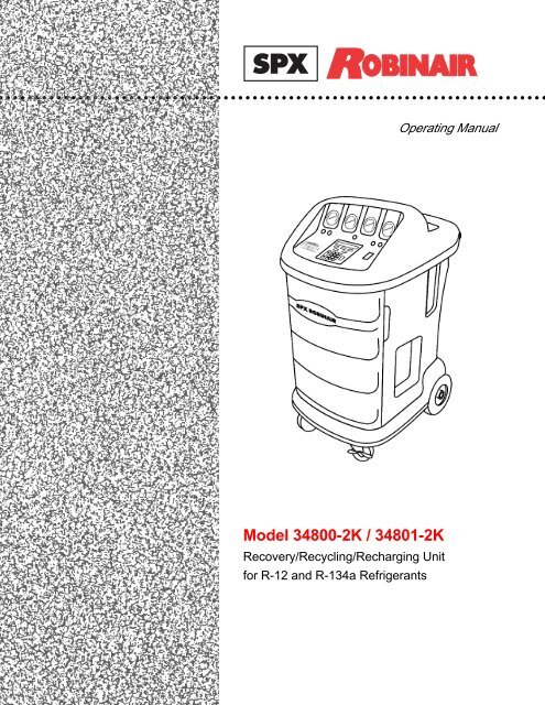
○ ○ ○ ○ ○ ○ ○ ○ ○ ○ ○ ○ ○ ○ ○ ○ ○ ○ ○ ○ ○ ○ ○ ○ ○ ○ ○ ○ ○ ○ ○ ○ ○ ○ ○ ○ ○ ○ ○ ○ ○ ○ ○ ○ ○ ○ ○ ○ ○ ○ ○ ○ ○ ○ ○ ○ ○ ○ ○ ○ ○ ○ ○ ○ ○ ○ ○ ○ ○ ○ ○ ○ ○ ○ ○ ○Operating ManualModel <strong>34800</strong>-<strong>2K</strong> / 34801-<strong>2K</strong><strong>Recovery</strong>/Recycling/Recharging <strong>Unit</strong>for R-<strong>12</strong> and R-<strong>134a</strong> Refrigerants
Refrigerant <strong>Recovery</strong>,Recycling and Recharging StationSeries: <strong>34800</strong>-<strong>2K</strong>/34801-<strong>2K</strong>Refrigerants: R-<strong>12</strong> and R-<strong>134a</strong>WARNINGPRESSURIZED TANK CONTAINS LIQUID REFRIGERANT. OVERFILLING OF THE TANK MAY CAUSE VIOLENTEXPLOSION AND POSSIBLE INJURY OR DEATH. Refer to the instruction manual for tank specifications and orderinginformation. Do not recover refrigerants into a non-refillable storage container! Federal regulations require refrigerant tobe transported only in containers meeting DOT spec. 4BW or DOT spec. 4BA.ALL HOSES MAY CONTAIN LIQUID REFRIGERANT UNDER PRESSURE. Contact with refrigerant may cause injury.Wear proper protective equipment, including safety goggles. Disconnect hoses with extreme caution.HIGH VOLTAGE ELECTRICITY INSIDE PANELS. RISK OF ELECTRICAL SHOCK. Disconnect power before servicingunit. Refer to the instruction manual.TO REDUCE THE RISK OF FIRE, avoid the use of an extension cord because theextension cord may overheat. However, if you must use an extension cord, use No. 14 AWG at the minimum and asshort as possible. Do not use this equipment in the vicinity of spilled or open containers of gasoline or other flammablesubstances.Use this equipment in locations with mechanical ventilation that provides at least four air changes per hour or locate theequipment at least 18 inches above the floor.Make certain all safety devices are functioning properly before operating the unit. Before operating, read and follow theinstructions and warnings in this manual.CAUTION: SHOULD BE OPERATED BY QUALIFIED PERSONNEL. Operator must be familiar with air conditioningand refrigeration systems, refrigerants and the dangers of pressurized components.Use only with R-<strong>12</strong> or R-<strong>134a</strong>. This equipment is not designed for any other purpose than recovering, recyclingor recharging refrigerants! Do not mix refrigerant types!ATTENTION!Ce réservoir sous pression contient du frigorigène liquide. S’il est surchargé, ce réservoir peut exploser et causer desblessures ou la mort.ATTENTION. Débrancher avant la maintenance.ATTENTION. Pour réduire les risques d’incendie, ne pas utiliser de cordon prolongateur de section inférieure à 14 AWGde facon à éviter la surchauffe du cordon.ATTENTION. Utiliser seulement du frigorigène R-<strong>134a</strong>.OPERATING NOTESAt temperatures exceeding <strong>12</strong>0 o F / 49 o C, wait 10 minutes between recovery jobs.R-<strong>12</strong> and R-<strong>134a</strong> WARNINGS!Use the Series <strong>34800</strong>-<strong>2K</strong>/34801-<strong>2K</strong> only with R-<strong>12</strong> or R-<strong>134a</strong>! Cross-contamination with other refrigerant types will causesevere damage to the A/C system and to service tools and equipment. Do not mix refrigerant types through a system orin the same container!Avoid breathing A/C refrigerant and lubricant vapor or mist. Exposure may irritate eyes, nose and throat. To removeR-<strong>12</strong> or R-<strong>134a</strong> from the A/C system, use service equipment certified to meet the requirements of SAE-J2210 (R-<strong>12</strong> orR-<strong>134a</strong> recycling equipment). If accidental system discharge occurs, ventilate work area before resuming service.R-<strong>12</strong> or HFC-<strong>134a</strong> service equipment or vehicle A/C systems should not be pressure tested or leak tested with compressedair. Some mixtures of air/HFC-R-<strong>12</strong> /R-<strong>134a</strong> have been shown to be combustible at elevated pressures. Thesemixtures are potentially dangerous and may result in fire or explosion causing injury or property damage.Additional health and safety information may be obtained from refrigerant and lubricant manufacturers.
Table of ContentsIntroduction ............................................................................................ 2Glossary of Terms ............................................................................... 2Set-Up Instructions................................................................................... 4Initial Set-Up ........................................................................................ 4Operating Guidelines .............................................................................. 6Using the Selection Menu ..................................................................... 6Change Filter ....................................................................................... 6Recycle ................................................................................................ 6External Storage Vessel (ESV) Refill R-<strong>12</strong> ............................................... 7External Storage Vessel (ESV) Refill R-<strong>134a</strong> ........................................... 8Vacuum Oil Time ................................................................................. 8Filter Capacity. .................................................................................... 8Basic/Advanced Prompts ..................................................................... 9Selecting a <strong>Unit</strong> (Metric/English) ........................................................... 9Language Select ................................................................................... 9Using the Control Panel ...................................................................... 10Keypad Functions .............................................................................. 11Operating Instructions ........................................................................... <strong>12</strong>Operating Tips ................................................................................... <strong>12</strong>Recovering Refrigerant ....................................................................... 13Evacuating the A/C System ................................................................ 15Replenishing A/C System Oil .............................................................. 17Recharging the A/C System ................................................................ 18Maintenance Instructions ....................................................................... 20Replacing the Filter-Drier .................................................................... 20Changing the Vacuum Pump Oil ......................................................... 21Checking for Leaks ............................................................................. 22Electrical Protection ............................................................................ 23General Maintenance ......................................................................... 23Replacement Parts List (<strong>34800</strong>-<strong>2K</strong>) ......................................................... 24Replacement Parts List (34801-<strong>2K</strong>) ......................................................... 26Flow Diagram ....................................................................................... 27Wiring Schematic .................................................................................. 28Limited Warranty .................................................................................. 29U.S. Patents: 4,523,897; 4,688,388 Re 33,2<strong>12</strong>; 4,768,347; 4,805,416; 4,809,520; 4,878,356; 4,938,031;5,005,369; 5,005,375; 5,038,578; 5,042,271; 5,209,653; 5,248,<strong>12</strong>5 Australian Patent: 613,058 CanadianPatents: 1,311,621; 1,311,622; 2,0<strong>12</strong>,620; 2,026,348 European Patent: 0 315 296 Bl German Patent: 03<strong>12</strong>96Mexican Patent: 16208 OTHER U.S. AND FOREIGN PATENTS PENDING.Mfd. by <strong>Robinair</strong>, SPX Corporation, Montpelier, OH 43543<strong>34800</strong>-<strong>2K</strong>/34801-<strong>2K</strong> Cool-<strong>Tech</strong> <strong>Recovery</strong>/Recycling/Recharging <strong>Unit</strong>1
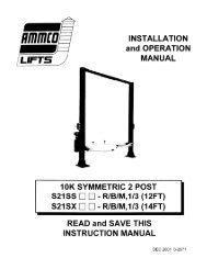
RECOVERMENUSTARTVACUUMCLEARVAC-CHARGESTOPENTERCHARGEF1IntroductionThis manual contains important safety procedures concerning theoperation, use, and maintenance of this product. Failure to follow theinstructions contained in this manual may result in serious injury. If you areunable to understand any of the contents of this manual, please bring it tothe attention of your supervisor. Do not operate this equipment unless youhave read and understood the contents of this manual.The <strong>34800</strong>-<strong>2K</strong> and 34801-<strong>2K</strong> models are designed to be used on R-<strong>12</strong> and R-<strong>134a</strong>vehicles. They are compatible with existing service equipment and standard serviceprocedures.The <strong>34800</strong>-<strong>2K</strong> model is UL-listed. The 34801-<strong>2K</strong> is CE approved. Both are singlepass systems that meet the SAE specifications for recycled refrigerant.To validate your warranty, complete the warranty card attached to your unit andreturn it within ten days from date of purchase.GLOSSARY OF TERMSA/C System<strong>Unit</strong>External Storage VesselSource TankThe air conditioning system being serviced.The refrigerant recovery/recycling/recharging unit.The refillable refrigerant storage vessel designedspecifically for this unit.A disposable tank of new refrigerant used to refillthe external storage vessel.Low SideGaugeHigh SideGaugeLow SideGaugeHigh SideGaugeLow SideValveLow SideValveVACUUMRECOVERCLOSEDCLOSEDVACUUM OIL INJECTRECOVER CHARGE1 2 34 5 67 8 90VACUUMRECOVERCLOSEDCLOSEDVACUUMOIL INJECTRECOVER CHARGERECOVERVACUUMVAC-CHARGECHARGEHigh SideValveMain PowerSwitchHigh SideValveKeypadMENUSTART1 247 8CLEAR03695F1ENTERSTOPDiagram of the <strong>34800</strong>-<strong>2K</strong> Control PanelINST 093<strong>12</strong>© 2001 <strong>Robinair</strong>, SPX Corporation
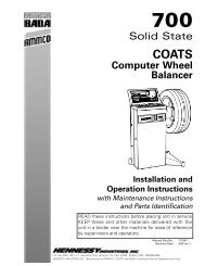
Set-Up Instructions102 414Diagram of <strong>Unit</strong>’s Components—External View111. Oil Injection Valves2. R-<strong>134a</strong> Hoses113. Scales4. Oil Injection Bottles5. 15A Breaker (7.5A for 34801-<strong>2K</strong>)25686. 3A Breaker (1.5A for 34801-<strong>2K</strong>)7. Hose Holders78. External Storage Vessel (ESV)9. Power Cord Receptacle910. Quick Couplers11. R-<strong>12</strong> Hoses8INST 09413Diagram of <strong>Unit</strong>’s Components—Internal View1. Oil Drain Bottle2. Compressor3. Vacuum Pump4. Filter5. Manifold Block6. Air Purge Assembly7. Vacuum Pump Receptacle8. Accumulator9. Fan6542957813INST 0942<strong>34800</strong>-<strong>2K</strong>/34801-<strong>2K</strong> Cool-<strong>Tech</strong> <strong>Recovery</strong>/Recycling/Recharging <strong>Unit</strong>3
Set-Up InstructionsINITIAL SET-UPCAUTION! R-<strong>134a</strong> systems have special fittings (per SAEspecifications) to avoid cross-contamination with R-<strong>12</strong> systems. Donot attempt to adapt your unit for another refrigerant — systemfailure will result! Read and follow all warnings at the beginning ofthis manual before operating the unit.CAUTION! Avoid the use of an extension cord because theextension cord may overheat. However, if you must use anextension cord, use a No. 14 AWG minimum and keep the cord asshort as possible.IMPORTANT!You must pressthe MENU key toaccess all thefunctions.1. Lock both front casters of the unit by stepping on the cam brake levers, plugthe power cord into the power cord receptacle (Item 9 in the INST 0941drawing on page 3). Turn on the MAIN POWER switch.2. The first time the unit is powered up it will start in the initial setup mode.3. The first step is to select a language. Use the UP and DOWN arrow keys toselect desired language. Press START to save the currently displayed language.4. Next select the operating units. Toggle between UNITS ENGLISH and UNITSMETRIC using the arrow keys. Press START to save the currently displayedchoice.5. Toggle between BASIC/ADVANCED using the arrow keys. Use the BASICPROMPT option to receive step-by-step, on-screen prompting through anyprocedure. Use ADVANCED PROMPT once you know the procedure and nolonger need the step-by-step routine. Press START to save the currentlydisplayed choice.NOTE: The vacuum pump is shipped without oil in the reservoir. Before startingthe pump, oil must be added to the pump or damage to the pump may occur.6. Press START to begin the Oil Fill process.7. Attach the flexible tube and cap to the oil bottle and pour eight ounces ofvacuum pump oil into the fill port.8. Press the START key. While the vacuum pump is running, slowly add oil untilthe level rises to the center of the reservoir's sight glass.9. Press the STOP key and replace the black plastic plug on the fill port.10.Use the F1 (Mode) key to select which mode to set up first R<strong>12</strong> or R134.Press START to continue. (After setting up the first mode the unit will promptyou to set up the other mode.)4© 2001 <strong>Robinair</strong>, SPX Corporation
Set-Up Instructions10. Connect the service hoses to the side that is being set up, turn both panelvalves to RECOVER/VACUUM Set Up and Instructionspress START. The unit willautomatically run a five minute vacuum to clear all internal air.11. After the vacuum is complete connect the low side service hose with adapter toa source tank. (For R-<strong>134a</strong> use tank to quick-coupler adapter PN 116<strong>12</strong>1, forR<strong>12</strong> use the 6" yellow adapter PN 710778. Both are included with unit)NOTE: If using a refillable tank, install the tank upside down and connect the lowside service hose to the vapor valve.<strong>12</strong>.Open the tank valve and invert the tank, press START when finished14. Press START to begin filling the external storage vessel.15. The unit stops when a sufficient amount of refrigerant has been transferred tothe internal tank or when the source tank is empty. Press the STOP key topause the process. Press STOP again to exit or START to resume . Thisprocess takes 15-20 minutes.IMPORTANT!For maximumperformance, besure to changethe vacuumpump oilfrequently.IMPORTANT!Be sure thepump isrunning whenadding oil.NOTE: Add at least 8 lb. (3.6 kg) of refrigerant before stopping the processto ensure that enough refrigerant is available for charging.16.When the fill process is complete you may press STOPto exit.17. Disconnect the source tank from the low side servicehose .1. Oil Fill Port2. Sight Glass3. Oil Drain18. The first mode is now ready to use, you will be promptedto set up the remaining mode. Select the other mode and pressSTART. Follow steps 10 - 17 for the other mode.<strong>12</strong>319. The unit is now ready to operate.NOTE: There is no need to calibrate the scale as it is calibratedat the factory.INST0943<strong>34800</strong>-<strong>2K</strong>/34801-<strong>2K</strong> Cool-<strong>Tech</strong> <strong>Recovery</strong>/Recycling/Recharging <strong>Unit</strong>5
Operating GuidelinesUSING THE SELECTION MENU1. Press the MENU button. The top line of the display reads SET UP MENU.2. Use the UP and DOWN arrow keys to scroll through the menu choices displayedon the second line. The menu choices are (in order of appearance):1. SELECT LANGUAGE 2. SELECT UNITS (ENGLISH/METRIC3. TANK REFILL 4. RECYCLE ONLY5. FILTER CAPACITY 6. CHANGE FILTER7. VACUUM OIL TIME 8. CHANGE VACUUM PUMP OIL9. SELECT PROMPTS 10. CHANGE DEFAULTS(Password Protected)11. VERSION X.XX4. Press START to make a choice from the menu. Press STOP to pause anyprocess and STOP a second time to exit any process.CHANGE FILTERThe filter-drier removes acid, particulates, and water from the refrigerant. Changethe filter-drier after 150 pounds (68 kg) of refrigerant has been filtered. SeeREPLACING THE FILTER DRIER on page 20 of the maintenance section of thismanual.RECYCLEManual recycling may be necessary if excessive air and/or moisture is recovered fromthe A/C system.1. Press the MENU key. Use the arrow keys to select RECYCLE ONLY andpress START to begin.2. Press the START button to start recycling. To pause recycling, press theSTOP key. To terminate recycling, press the STOP key again or pressSTART to resume.6© 2001 <strong>Robinair</strong>, SPX Corporation
Operating GuidelinesTANK REFILL (R-<strong>12</strong>)NOTE: If using a refillable tank, place the tank upside down and connect the lowside service hose to the vapor valve.Use the F1 (Mode) key to select R<strong>12</strong> mode (Press and hold F1 for severalseconds to change modes)1. Press the MENU key. Use the arrow keys to select TANK REFILL and pressSTART to begin.2. Connect the 6" yellow adapter (PN 710778 included with unit) to the end ofthe low side service hose.4. Connect the low side service hose with adapter to a source tank.5. Open the tank valve and invert the tank.6. Press the START key and the tank automatically refills. The unit stops when asufficient amount of refrigerant has been transferred to the ESV or if the sourcetank is empty. Press the STOP key to pause the process. Press STOP againto exit or START to resume before the external storage vessel is full.7. When the fill process is complete press STOP to exit.R-<strong>12</strong>Low SideService HoseSourceTankESVINST0710<strong>34800</strong>-<strong>2K</strong>/34801-<strong>2K</strong> Cool-<strong>Tech</strong> <strong>Recovery</strong>/Recycling/Recharging <strong>Unit</strong>7
Operating GuidelinesTANK REFILL (R-<strong>134a</strong>)Use the F1 (Mode) key to select R-<strong>134a</strong> mode (Press and hold F1 for severalseconds to change modes)1. Press the MENU key. Use the arrow keys to select TANK REFILL and pressSTART to begin.2. Connect the tank to quick-coupler adapter (PN 116<strong>12</strong>1 included with unit) tothe low side service hose.3. Connect the low side hose with adapter to a source tank.4. Open the tank valve and invert the tank.NOTE: If using a refillable tank invert the tank and connect the hose to the vaporvalve.5. Press the START key and the tank automatically refills. The unit stops when asufficient amount of refrigerant has been transferred to the internal tank or if thesource tank is empty. Press the STOP key to pause the process. Press STOPagain to exit or START to resume before the internal tank is full.6. When the fill process is complete press STOP to exit.VACUUM OIL TIMEThis function displays how long the vacuum pump has ran since the last oil change.1. Press the MENU key. Use the arrow keys to select VACUUM OIL TIME andpress START to begin.2. The display reads: OIL TIME = XX:XX This shows how long the pump hasran since the last oil change. The time resets to zero after a VACUUM PUMPOIL CHANGE. See page 21 of this manual for details.3. Press STOP to exitFILTER CAPACITYThis function is used to show the operator how many pounds of refrigerant havebeen recovered since the last filter change.1. Press the MENU key. Use the arrow keys to select FILTER CAPACITY andpress START to begin2. The display reads: FILTERED= XXXlbs(kg). This shows how muchrefrigerant has passed through the filter. The amount filtered resets to zero aftera FILTER CHANGE. See page 20 of this manual for details.8© 2001 <strong>Robinair</strong>, SPX Corporation
Operating GuidelinesNOTE: The displayed filter amount is for the mode the unit is currently operating in.3. Press STOP to exit.SELECT PROMPT (BASIC/ADVANCED)Use the BASIC PROMPT option to receive step-by-step, on-screen prompting through any procedure. UseADVANCED PROMPT once you know the procedure and no longer need the step-by-step routine.1. Press the MENU key. Use the arrow keys to choose SELECT PROMPT and press START tobegin.2. Toggle between BASIC/ADVANCED using the arrow keys.3. Press the START to save the current choice and exit.NOTE: This manual is written for the BASIC PROMPT option.SELECTING A UNIT (Metric/English)1. Press the MENU key. Use the arrow keys to choose SELECT UNITS and press START to begin.2. Toggle between UNITS ENGLISH and UNITS METRIC using the arrow key.3. Press START to save the current choice and exit.LANGUAGE SELECTThe operator can choose between English, Spanish, French, Italian or German.1. Press the MENU key. Use the arrow keys to choose SELECT LANGUAGE and press START tobegin2. Use the UP and DOWN arrows to scroll through the languages and then press3. Press START to save the current choice. Press STOP to exit without saving.CHANGE DEFAULTSFor service use only.VERSIONDisplays the current software revision.<strong>34800</strong>-<strong>2K</strong>/34801-<strong>2K</strong> Cool-<strong>Tech</strong> <strong>Recovery</strong>/Recycling/Recharging <strong>Unit</strong>9
RECOVERMENUSTARTVACUUMCLEARVAC-CHARGEENTERSTOPCHARGEOperating GuidelinesUSING THE CONTROL PANELThe control panel has various components that control specific operatingfunctions.MAIN POWER SWITCH — Supplies electrical power to the control panel.DIGITAL DISPLAY — Used on the visual interface between the operator andthe machine.LOW SIDE MANIFOLD GAUGE — Connects to an A/C system and showsthe system’s low side pressure.HIGH SIDE MANIFOLD GAUGE — Connects to an A/C system and showsthe system’s high side pressure.LOW SIDE VALVE — Controls the low side flow from the A/C system throughthe unit. It has two positions: 1) Vacuum/Recover, and 2) Closed.HIGH SIDE VALVE — Controls the high side flow from the A/C systemthrough the unit. It has three positions: 1) Vacuum/Recover, 2) Closed,3) Oil Inject/Charge.34346CLOSEDCLOSEDCLOSEDCLOSED5VACUUMRECOVERVACUUMRECOVEROIL INJECTCHARGEVACUUMRECOVERVACUUMRECOVEROIL INJECTCHARGE61 2 34 5 67 8 9 0F1152INST 09327Diagram of Control Panel1. Main Power Switch2. Display3. Low Side Gauge4. High Side Gauge5. High Side Valve6. Low Side Valve7. Keypad10© 2001 <strong>Robinair</strong>, SPX Corporation
Operating GuidelinesKEYPAD FUNCTIONSIn addition to the number keys, the keypad contains special keys that accomplishspecific operating functions.• START—Begins or resumes a function.• STOP—Terminates or pauses a function.• RECOVER—Activates the recovery sequence.• VACUUM—Activates the vacuum and automatic recycling sequence.• VAC-CHARGE—Activates the vacuum and automatic recycling sequencefollowed by a charge.• CHARGE—Charges the A/C system with a programmed amount ofrefrigerant.• MENU—Enters the selection menu.• UP/DOWN ARROWS—Used for scrolling through the menu items.• CLEAR—Factory use only• ENTER—Factory use only• F1 (Mode) —Press and hold to select the operating mode (R-<strong>12</strong> or R-<strong>134a</strong>)RECOVERVACUUMVAC-CHARGECHARGESTARTSTOPMENU147CLEAR2580369ENTERF1INST 0933Diagram of Keypad<strong>34800</strong>-<strong>2K</strong>/34801-<strong>2K</strong> Cool-<strong>Tech</strong> <strong>Recovery</strong>/Recycling/Recharging <strong>Unit</strong>11
Operating InstructionsOPERATING TIPSFollow the recommended service procedure for the containment of R-<strong>12</strong> and R-<strong>134a</strong>.The recovery compressor is not a vacuum pump. The compressor pulls the A/Csystem to a partial vacuum only. You must use the unit’s vacuum cycle to removemoisture from the A/C system. We recommend a minimum 15-minute vacuum withmore time as required by the system manufacturer.This unit is designed to be used with the manifold gauge set built into the controlpanel.It includes a 6 cfm (142 l/m) vacuum pump for fast, thorough evacuation. Be sure tochange the vacuum pump oil after 10 hours of vacuum pump use.R-<strong>12</strong> and R-<strong>134a</strong> systems require special oils. Refer to the A/C systemmanufacturer’s service manuals for oil specifications.Pressing the START and STOP keys together for several seconds will exit any modeand reset the controlNOTE: The following operating instructions are written to be used with theBASIC PROMPTS mode of operation. It is recommended that the BASICPROMPTS mode is used until the operator becomes very familiar with theoperation of the unit. See the OPERATING GUIDELINES section of this manualfor instructions on how to select between BASIC PROMPTS and ADVANCEDPROMPTS.<strong>12</strong>© 2001 <strong>Robinair</strong>, SPX Corporation
RECOVERMENUSTARTVACUUMCLEARVAC-CHARGEENTERSTOPCHARGERECOVERING REFRIGERANTWARNINGOperating InstructionsAlways wear safety goggles when working with refrigerant. Read andfollow all warnings at the beginning of this manual before operatingthe unit.1. Connect the power cord to the back of the unit and plug into the proper voltageoutlet.2. Turn on the MAIN POWER and if necessary empty the oil drain bottle located onthe right hand side of the unit.3. Ensure the unit is in the proper refrigerant mode. Use the F1 (Mode) key toselect the correct refrigerant mode.4. Press the RECOVER button.5. If 150 pounds (68 kg) or more of refrigerant has been recovered since the lastfilter-drier change, the display reads FILTER WEIGHT XXX lb (XX kg).Press START to continue STOP to exit.NOTE: See the filter change procedure on page 20 of this manual for details onreplacing the filter.6. Connect the high and low side hoses to the A/C system and on R-<strong>134a</strong> systemsopen the coupler valves.7. Put Low Side Valve in the Recover/Vacuum position. Put High Side Valve inthe Recover/Vacuum position. Press START to continue.9. If the system pressure is below 25 psi, the display reads: LOW SYSTEMPRESSURE until the pressure increases or the START button is pressed. Youmay press STOP to exit at this point.9. If the unit has refrigerant in the low-side plumbing, it begins the clearingprocess and displays CLEARING IN PROGRESS. If you wish to skip theclearing operation or stop the clearing prematurely, press the START key.Manifold GaugesManifold GaugesCLOSEDCLOSEDCLOSEDCLOSEDVACUUMRECOVERVACUUMRECOVEROIL INJECTCHARGEVACUUMRECOVERVACUUMRECOVEROIL INJECTCHARGE1 234 5 67 8 90F1ValvesOpenRecoverINST 0934Diagram of Control Panel During <strong>Recovery</strong><strong>34800</strong>-<strong>2K</strong>/34801-<strong>2K</strong> Cool-<strong>Tech</strong> <strong>Recovery</strong>/Recycling/Recharging <strong>Unit</strong>13
Operating Instructions10. When the system has recovered to a vacuum level of approximately 13 in. Hg., the compressorautomatically shuts off.11. The unit then goes into automatic oil drain and the display reads: OIL DRAINING. Oil draining canrequire up to 90 seconds to complete.<strong>12</strong>. After the oil drain is complete, the display alternates between:RECOVERY COMPLETE CHECK OIL BOTTLE.RECOVERED XX.XX lbs. (X.XXkg) RECOVERED XX.XX lbs. (X.XXkg)NOTE: The displayed recovered weight can vary depending on ambient conditions and should not beused as an indicator of scale accuracy.13. Check the oil drain bottle and note the amount of oil that was removed from the A/C system. This isthe amount of oil that must be charged into the A/C system after evacuation is complete.14. To ensure complete recovery of refrigerant, wait 5 minutes and watch the manifold gauges for a risein pressure above 0 in. Hg. A pressure rise may occur if there was freezing in the A/C system duringrecovery. If a rise occurs, press the START button to resume the recovery process. Repeat as neededuntil the system pressure holds for two minutes, then press STOP to exit.<strong>Recovery</strong> is now complete. You are now ready to make any repairs to the A/C system, if necessary, oradvance to the Evacuation Process.Diagram of the Oil Injection SystemOil Injector BottlesOil Drain BottlesINST 071314© 2001 <strong>Robinair</strong>, SPX Corporation
RECOVERMENUSTARTVACUUMVAC-CHARGEENTERSTOPCHARGEEVACUATING THE A/C SYSTEMOperating InstructionsWARNINGAlways wear safety goggles when working with refrigerant. Use onlyauthorized refillable refrigerant tanks. Read and follow all warnings at thebeginning of this manual before operating the unit. In addition to thenumber keys, the keypad contains special keys that accomplish specificoperating functions.IMPORTANT!You shouldevacuate for atleast 15 minutesto ensureadequate moistureand contaminantremoval.NOTE: If any oil was drained from the system during recovery, DO NOT use theVAC-CHARGE feature. The oil must be replenished into the A/C system,which is not possible when the VAC-CHARGE function is used.NOTE: If the vacuum pump has been run more than 10 hours since the last oilchange, the display reads: VACUUM OIL TIME XX:XX. Press the STOP keyto change the vacuum pump oil or press the START key to continue.Instructions for changing the vacuum pump oil are located in the maintenancesection of this manual. NOTE: Vacuum Pump oil should be changed after 10hours of use to maintain maximum performance and endurance levels.IMPORTANT!If the vacuumpump has run for10 or more hourswithout an oilchange, themessageVACUUM OILTIME = Xhr. XminXsec appears onthe display.Change thepump oilfollowing theprocedures in theMAINTENANCEINSTRUCTIONS.NOTE: If the system being evacuated contains a pressure over 25 psi at any pointduring the evacuation, the display reads PRESSURE EXISTS. This messageindicates that the A/C system contains refrigerant, press any key to continue.Press the RECOVERY key to recover any refrigerant in the system. (SeeRECOVERING REFRIGERANT page 13) After recovery is complete, return toEvacuating the A/C System.VACUUMRECOVERCLOSEDVACUUMRECOVERCLOSEDOIL INJECTCHARGE1 2 34 5 67 8 9CLEAR0F1VACUUMRECOVERCLOSEDVACUUMRECOVERCLOSEDOIL INJECTCHARGEValves OpenVacuumVac-ChargeThe Control Panel During Evacuation<strong>34800</strong>-<strong>2K</strong>/34801-<strong>2K</strong> Cool-<strong>Tech</strong> <strong>Recovery</strong>/Recycling/Recharging <strong>Unit</strong>INST 093515
Operating InstructionsVAC-CHARGENOTE: Ensure the unit is in the proper refrigerant mode. Use the F1 (Mode) keyto select the correct refrigerant mode.1. Press the VAC-CHARGE key to select the VAC-CHARGE feature.2. Ensure the service hoses are connected and panel valves are in theVACUUM/RECOVER position. Press START3. Press the START key to charge the default amount of refrigerant or use thenumber keys to enter the desired charge weight. Then press the START key.4. If the weight entered will leave less than 3 lbs (1.36 kg). of refrigerant in theexternal storage vessel, the VAC-CHARGE process does not begin and thedisplay reads INSUFFICIENT REFRIG. At this point, refrigerant must beadded to the external storage vessel. See pages 7 and 8 of this manual forexternal storage vessel refill instructions and then return to Step 1 ofEVACUATING the A/C system.5. If the external storage vessel contains a sufficient amount of refrigerant, pressthe START key to accept the default evacuation time of 15:00 minutes or enterthe desired vacuum time by using the number keys. Then press the START key.IMPORTANT!You shouldevacuate the A/Csystem for atleast 15 minutesto ensureadequatemoisture andcontaminantremoval.6. The unit automatically charges the A/C system 10 seconds after the specifiedvacuum time has elapsed.7. Advance to step 4 of RECHARGING the A/C SYSTEM in this manual tocomplete the charging process.NOTE: It is not necessary to change the High side panel valve from vacuum to chargewhen performing the VAC-CHARGE functionVACUUMNOTE: Ensure the unit is in the proper refrigerant mode. Use the F1 (Mode)key to select the correct refrigerant mode.1. Press the VACUUM key.2. Ensure the service hoses are connected and panel valves are in theVACUUM/RECOVER position. Press START3. Press the START key to accept the default evacuation time of 15:00 minutesor enter the desired vacuum time by using the number keys and press theSTART key.4. The unit evacuates the A/C system and stops when the specified time haselapsed. Pressing the STOP key will pause the process. Press START toresume or STOP again to exit.5. You are now ready to replenish the A/C system oil (if necessary) or advance toRecharging the A/C System.16© 2001 <strong>Robinair</strong>, SPX Corporation
RECOVERSTARTVACUUMCLEARVAC-CHARGESTOPENTERCHARGEREPLENISHING A/C SYSTEM OILOperating InstructionsBefore charging the A/C system, you must replenish any oil removed from the A/Csystem during the recovery process.1. Select the correct oil for the A/C system being serviced. Refer to the vehiclemanufacturer's service manual.CAUTION! To prevent air from entering the A/C system, never let the oillevel drop below the pick-up tube while charging or replenishing.2. Adjust the O-ring around the oil injector bottle to the required oil charge level.For example, if the bottle's oil level is at 4 ounces and you need 1/2 ounce ofoil to replenish the A/C system, place the o-ring at the 3 1/2 ounce level.3. Install the bottle on the oil injection assembly on the back of the unit.CAUTION! Never open the oil injection valve while there is positivepressure in the A/C system. This action could blow oil back through thebottle vent.4. Place the Low Side valve in the Closed position. Place the High Side valve in theOil Inject/Charge position.5. Turn the oil injection valve at the top of the bottle and watch the level of oil beingdrawn into the A/C system. This process takes only seconds—watch carefully!6. Turn OFF the valve when the required oil charge has been pulled into the system.CAUTION! Always perform a charge after any oil inject to insure all of theoil is delivered to the A/C system.OilInjectorBottleClosedCLOSEDCLOSEDCLOSEDCLOSEDVACUUMRECOVERVACUUMRECOVEROIL INJECTCHARGEVACUUMRECOVERVACUUMRECOVEROIL INJECTCHARGE1 2 34 67 8 90MENU5F1Oil Inject/ChargeOilDrainBottleINST 0936 INST 0713<strong>34800</strong>-<strong>2K</strong>/34801-<strong>2K</strong> Cool-<strong>Tech</strong> <strong>Recovery</strong>/Recycling/Recharging <strong>Unit</strong>17
RECOVERSTARTVACUUMCLEARVAC-CHARGESTOPENTERCHARGEOperating InstructionsRECHARGING THE A/C SYSTEMWARNINGAlways wear safety goggles when working with refrigerant. Use onlyauthorized refillable refrigerant tanks. Disconnect hoses with extremecaution!All hoses may contain liquid refrigerant under pressure. Read andfollow all warnings at the beginning of this manual before operating theunit.NOTE: Ensure the unit is in the proper refrigerant mode. Use the F1 (Mode) keyto select the correct refrigerant mode.1. Press the CHARGE button.2. Put the Low Side Valve in the Closed position. Put the High Side Valve inthe Oil Inject/Charge position. Press START to continueIMPORTANT!You shouldevacuate the A/Csystem for atleast 15 minutesfor adequatemoisture andcontaminantremoval.3. Accept either the default weight by pressing START or type in a weight withthe number keys and press START.4. If the weight entered will leave less than 3 lbs (1.36 kg) of refrigerantin the external storage vessel, the charge function will not start andthe display reads:INSUFFICIENT REFRIG.PRESS A<strong>NY</strong> KEY TO EXITClosedVACUUMRECOVERCLOSEDCLOSEDVACUUM OIL INJECTRECOVER CHARGEVACUUMRECOVERCLOSEDCLOSEDVACUUM OIL INJECTRECOVER CHARGESee the Operating Guidelines section of the manual forrefill instructions.5. Upon entering a valid charge weight, the display reads:CHARGE IN PROGRESSCHARGED= X.XX lbs. (X.XX kg)Oil Inject/Charge1 2 34 67 8 90MENU5INST 0936F16. If, during the charge cycle, the weight fails to charge 0.05 lbs (0.02 kg) in 30seconds, the unit intermittently beeps while the display alternates between:CHARGING HAS SLOWEDPRESS START TO RETRYCHARGE HAS SLOWEDOR STOP TO EXIT18© 2001 <strong>Robinair</strong>, SPX Corporation
Operating Instructions7. Pressing the START button when the charging is slowed causes the charge toresume. If charging does not complete see the SLOW CHARGE PROCEDUREbelow.8. When the charge is complete the display will showCHARGE COMPLETEX.XXlb (kg) CHARGED9. For a R-<strong>134a</strong> System close the high and low side coupler valves. Remove theservice hoses from the A/C system.The A/C system is now ready for use.SLOW CHARGE PROCEDURECAUTION! Be sure the high side manifold valve is closed before startingthe vehicle A/C system.WARNINGBefore starting the vehicle's engine, check to see that it is in PARK orNEUTRAL, with the emergency brake ON. Never run a vehicle withoutadequate ventilation in the work area.1. Close the High Side Valve. Put the Low Side Valve in theRecover/Vacuum position.2. Start the vehicle and set the AC system to its maximum setting.3. Press START. The unit charges out of the low side inlet only,allowing the vehicle's compressor to pull the refrigerant into theA/C system.4. When the unit is finished charging, the display reads:5. Close the LOW SIDE manifold valve.6. Turn off the vehicle's engine.CHARGE COMPLETE.X.XX lb (kg) CHARGED7. For a R-<strong>134a</strong> System close the high and low side coupler valves. Remove theservice hoses from the A/C system.The A/C system is now ready for use.<strong>34800</strong>-<strong>2K</strong>/34801-<strong>2K</strong> Cool-<strong>Tech</strong> <strong>Recovery</strong>/Recycling/Recharging <strong>Unit</strong>19
Maintenance InstructionsREPLACING THE FILTER-DRIEROrder part #34724 for a replacement filter-drier. The filterdrieron this unit is designed to trap acid and particulates andis formulated to remove water from the refrigerant. You mustchange the filter-drier to assure adequate moisture andcontaminant removal.Typically, you can recycle up to 150 pounds (68 kilograms) ofrefrigerant between filter changes.CAUTION! For best results, use <strong>Robinair</strong> filterdriers(part no. 34724). All performance tests andclaims are based on using this specially-blended filterdrier.Use of another may affect performance results.Filter-DrierINST0477Filter1. Press the MENU button.2. Scroll through the menu to CHANGE FILTER and pressSTART.3. Press START again and the unit will begin clearing the filter.4. When clearing is complete, the display readsTURN UNIT OFF AND REPLACE FILTER.5. Turn off the main power and unplug the machine.6. Open the unit door and replace the old filter with the newfilter.Filter7. Close the unit door, plug in the machine, and turn on theMain Power.8. The filter change is now complete.Location of the Filter-DrierINST 094420© 2001 <strong>Robinair</strong>, SPX Corporation
Maintenance InstructionsCHANGING THE VACUUM PUMP OILFor maximum vacuum pump performance, change the vacuum pump oil every 10hours of operation.1. Turn on the MAIN POWER switch.2. Press the MENU button.NOTE: Do not connect the service hoses to a vehicle.3. Use the arrow keys to select CHANGE VACUUM PUMP OIL and pressSTART.4. Press START again to begin.5. The vacuum pump will run for two minutes. Allow the vacuum pump to run until itautomatically stops.6. Remove the black plastic plug on the oil fill port of the vacuum pump.7. Remove the oil drain cap from the vacuum pump and drain the oil into a suitablecontainer for proper disposal.IMPORTANT!Review current local,state, and federalstatutes, cases,laws, andregulations todetermine thecurrent status andappropriatedisposal method forpump oil. It is theresponsibility of theuser to determine ifa material is ahazardous waste atthe time of disposal.Ensure that you arein compliance withall applicable laws8. Replace the oil drain cap.9. Attach the flexible tube and cap to the oil bottle and pour eight ounces of vacuumpump oil into the fill port.10. Press the START key. While the vacuum pump is running, slowly add oil untilthe level rises to the center of the reservoir's sight glass.11. Press the STOP key and replace the black plastic plug onthe fill port.<strong>12</strong>. The unit is now ready to operate.<strong>34800</strong>-<strong>2K</strong>/34801-<strong>2K</strong> Cool-<strong>Tech</strong> <strong>Recovery</strong>/Recycling/Recharging <strong>Unit</strong>21
CLOSEMaintenance Instructions<strong>12</strong>6 34OPEN5<strong>12</strong>3Diagram of Vacuum PumpINST 007091. Oil Filler Tube2. Pump Exhaust3. Oil Fill Port4. Sight Glass5. Oil Drain Fitting6. InletINST09431. Oil Fill Port2. Sight Glass3. Oil DrainIMPORTANT!Inspect the unitperiodically forleaks. Themanufacturerdoes notreimburse for lostrefrigerant.CHECKING FOR LEAKSEvery three months, or as specified by local or state laws, you should check theunit for leaks.1. Turn off the MAIN POWER switch, and disconnect the power cord from theoutlet.2. Open door.3. Use a leak detector to probe all connections for refrigerant leaks. Tighten fittings ifa leak is indicated.4. Close door.22© 2001 <strong>Robinair</strong>, SPX Corporation
Maintenance InstructionsELECTRICAL PROTECTIONIf the circuit breaker trips, all power to the unit is lost. Press the circuit breakerbutton to reset. The circuit breaker is located near the fuse on the back of the unit.GENERAL MAINTENANCE1. On a regular basis, wipe off the unit with a clean cloth to remove grease, dustor other dirt.2. Periodically check the internal components for leaks—over time, fittings canloosen as the unit is moved. Open the unit door panel and trace lines with aleak detector. Also, check connections on the back of the unit. Tighten anyloose fittings or connections you may find.<strong>34800</strong>-<strong>2K</strong>/34801-<strong>2K</strong> Cool-<strong>Tech</strong> <strong>Recovery</strong>/Recycling/Recharging <strong>Unit</strong>23
Replacement PartsThe following is a list of replacement parts and accessories you may need to serviceor maintain your unit.We suggest you keep several filter-driers on hand so you will always be able tochange them and complete any recycling job that is in progress.Premium High Vacuum Pump Oil is also available in handy quart containers or inconvenient gallon containers:Quart (shipped <strong>12</strong> quarts per case) 13203Gallon (shipped 4 gallons per case) 13204<strong>34800</strong>-<strong>2K</strong> Replacement PartsR-<strong>12</strong> R-<strong>134a</strong>Replacement ReplacementComponent Part Number Part Number2496" Red Hose 68396A 6309696" Blue Hose 68296A 62096Fan RA17416 N/AFilter-Drier 34724 34724Compressor RA19735 RA19735Vacuum Pump RA15425 RA15425High Pressure Switch RA19427 RA19427Main Power Switch RA19344 RA19343Vacuum Switch RA18752 RA18752Pump Protection Switch RA19429 RA19429Automatic Expansion Valve RA19592 RA19592Scale Assembly RA19603 RA19603Control Module RA19769 RA19769High Side Gauge RA19742 RA19613Low Side Gauge RA19741 RA19614Low Side Coupler N/A 18190AHigh Side Coupler N/A 18191AAutomatic Air Purge RA19744 RA19743Solenoid Rebuild Kit RA19258 RA19258© 2001 <strong>Robinair</strong>, SPX Corporation
Replacement Parts34801-<strong>2K</strong> Replacement PartsComponent R-<strong>12</strong> R-<strong>134a</strong>Replacement ReplacementPart Number Part Number96" Red Hose 68396A 6309696" Blue Hose 68296A 62096Fan RA17516 N / AFilter-Drier 34724 34724Compressor RA19736 RA19736Vacuum Pump RA15428 RA15428High Pressure Switch RA19427 RA19427Main Power Switch RA19344 RA19343Vacuum Switch RA18752 RA18752Pump Protection Switch RA19429 RA19429Automatic Expansion Valve RA19592 RA19592Control Module RA19769 RA19769High Side Gauge RA19742 RA19613Low Side Gauge RA19741 RA19614Low Side Coupler N / A 18190AHigh Side Coupler N / A 18191AAutomatic Air Purge RA19744 RA19743Solenoid Rebuild Kit RA19258 RA19258UL Circuit RA19673 RA19673<strong>34800</strong>-<strong>2K</strong>/34801-<strong>2K</strong> Cool-<strong>Tech</strong> <strong>Recovery</strong>/Recycling/Recharging <strong>Unit</strong>25
INST 0945Flow DiagramSWITCH<strong>12</strong>3DESCRIPTIONHIGH PRESSURE SWITCH-MANIFOLDVACUUM PROTECTION SWITCH13" VACUUM SWITCH4 HIGH PRESSURE SWITCH-OIL DRAINSOLENOID<strong>12</strong>3456DESCRIPTIONRECOVERVACUUMCHARGERECYCLEOIL RETURNAIR PURGERECOVERXOOO*OOVACUUMOXOO**FUNCTIONRECYCLE CHARGE7 OIL DRAINOOOOXOX**OOXOOOO = OFFAIR PURGE CONTROLX = ON* = PERIODICALLY ONFROM AIR PURGEPORT ON TANK3UPPER BLOCKTO VAPOR PORTON TANK64LOWER BLOCK1A 1FROM LIQUIDPORT ONTANKCHECK VALVE3225THIS VALVE IS BUILTINTO LOWER BLOCKACHECK VALVELOCATED BETWEEN PORTS E AND FOF LOWER BLOCKMANIFOLD (ON CONTROL PANEL)LS HSOILINJECTORTO A/C SYSTEMTO A/C SYSTEMVACUUM PUMPCOMPRESSOR7TO DRAINBOTTLE426© 2001 <strong>Robinair</strong>, SPX Corporation
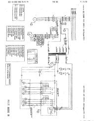
Wiring DiagramR<strong>12</strong> OIL DRAINSW4R134 OIL DRAINSW5R134 LOW PRESSSW6R134 VAC PROTSW7R<strong>12</strong> LOW PRESSSW8R<strong>12</strong> VAC PROTSW9R134 SCALEASSYGR<strong>12</strong> SCALEASSYGSHIELDSHIELDP14104115<strong>12</strong>61371418293WHITEWHITEREDREDYELLOWYELLOWORANGEORANGEPURPLEPURPLEBLACKBLACKNCNCP20<strong>12</strong>34BLACKGREENWHITEREDP211 BLACK234GREENWHITEREDLNGVACUUMPUMPOUTLET3THERMALPROTECTOR15COMPRESSORSTART RELAY1432STARTCAPACITORR<strong>12</strong> COMPRESSOR3THERMALPROTECTOR15 4 3COMPRESSORSTART RELAY1 2STARTCAPACITORR134 COMPRESSORR<strong>12</strong> OIL DRNSOL 11R134 OIL DRNSOL <strong>12</strong>R134 VACUUMSOL 2R134 CHARGESOL 3R134 RECOVERSOL 1R134 AIR PURGESOL 6R134 RECYCLESOL 4R134 OIL RTNSOL 5P27<strong>12</strong>345678BLUEBROWNWHITEBLACKYELLOWPURPLEP232103114<strong>12</strong>51361471581619REDREDYELLOWYELLOWWHITEWHITEBLACKBLACKORANGEORANGEBLUEBLUEGRAYGRAYPURPLEPURPLERECEPTACLEIEC320 INLETLT BLUEBROWNGRN/YELFANMAINPOWERSW1P10<strong>12</strong>GRN/YELLT. BLUE3 BROWNP11<strong>12</strong>34GRAYGRAYWHITEWHITE15 AMPBREAKER3 AMPBREAKERP28<strong>12</strong>BROWNBROWNHIGH PRESS3 21 R<strong>12</strong> SW2BROWN1HIGH PRESS3 2 R134 SW3P241 WHITE104115<strong>12</strong>6137148293WHITEORANGEORANGEBLUEBLUEBLACKBLACKGRAYGRAYPURPLEPURPLEREDREDR<strong>12</strong> RECYCLESOL 10R<strong>12</strong> CHARGESOL 9R<strong>12</strong> VACUUMSOL 8R<strong>12</strong> OIL RTNSOL 13R2 AIR PURGESOL 14R<strong>12</strong> RECOVERSOL 7NOTE: LINES SHOWN ASARE SUPPLIED AS PART OF A COMPONENTAND ARE NOT PART OF THE WIRING HARNESSInst0939<strong>34800</strong>-<strong>2K</strong>/34801-<strong>2K</strong> Cool-<strong>Tech</strong> <strong>Recovery</strong>/Recycling/Recharging <strong>Unit</strong>27
Limited Warranty<strong>Robinair</strong> Limited Warranty StatementRev. July 11, 2003This product is warranted to be free from defects in workmanship, materials, and components for aperiod of one year from date of purchase. All parts and labor required to repair defective productscovered under the warranty will be at no charge. The following restrictions apply:1. The limited warranty applies to the original purchaser only.2. The warranty applies to the product in normal usage situations only, as described in the OperatingManual. The product must also be serviced and maintained as specified.3. If the product fails, it will be repaired or replaced at the option of the manufacturer.4. Transportation charges for warranty service will be reimbursed by the factory upon verification of thewarranty claim and submission of a freight bill for normal ground service. Approval from themanufacturer must be obtained prior to shipping to an authorized service center.5. Warranty service claims are subject to authorized inspection for product defect(s).6. The manufacturer shall not be responsible for any additional costs associated with a product failureincluding, but not limited to, loss of work time, loss of refrigerant, cross-contamination of refrigerant,and unauthorized shipping and/or labor charges.7. All warranty service claims must be made within the specified warranty period. Proof-of-purchasedate must be supplied to the manufacturer.8. Use of recovery/recycling equipment with unauthorized refrigerants, sealants, or dyes will void thewarranty.• Authorized refrigerants are listed on the equipment or are available through the <strong>Tech</strong>nical ServiceDepartment.• The manufacturer prohibits the use of the recovery/recycling equipment on air conditioning (A/C)systems containing leak sealants, either of a seal-swelling or aerobic nature.• The manufacturer prohibits the use of dyes injected through the oil injection device on therecovery/recycling equipment.This Limited Warranty does NOT apply if:• The product, or product part, is broken by accident.• The product is misused, tampered with, or modified.• The product is used for recovering or recycling any substance other than the specified refrigerant type.This includes, but is not limited to, materials and chemicals used to seal leaks in A/C systems.• The product is equipped with an oil injection device that has been used to inject dye. The manufactureronly endorses the use of separate dye injection devices, and does not support the use of the oilinjection feature for this purpose.Note: Refillable refrigerant tanks are reusable.28© 2001 <strong>Robinair</strong>, SPX Corporation
CONVERSIONTABLEOZ.LBS.0.5 0.031.0 0.061.5 0.092.0 0.132.5 0.163.0 0.193.5 0.224.0 0.254.5 0.285.0 0.315.5 0.346.0 0.386.5 0.417.0 0.447.5 0.478.0 0.508.5 0.539.0 0.569.5 0.5910.0 0.6310.5 0.6911.0 0.6911.5 0.72<strong>12</strong>.0 0.75<strong>12</strong>.5 0.7813.0 0.8113.5 0.8414.0 0.8814.5 0.9115.0 0.9415.5 0.9716.0 1 lb.%Visit our web site atwww.robinair.comor call our Toll-Free<strong>Tech</strong>nical Support Line at800-822-5561in the continental U.S. or Canada.In all other locations, contact your local distributor. To help us serveyou better, please be prepared to provide the model number, serialnumber, and date of purchase.To validate your warranty, complete the warranty card attached to yourunit and return it within ten days from date of purchase.• NATIONWIDE NETWORK OF AUTHORIZED SERVICE CENTERSIf your unit needs repairs or replacement parts, contact the servicecenter in your area. For help in locating a service center, call the tollfree technical support line.Due to ongoing product improvements, we reserve the right to change design,specifications, and materials without notice.The <strong>34800</strong>-<strong>2K</strong> and 34801-<strong>2K</strong> are designed to meet all applicable agency certificationsincluding Underwriter's Laboratories, Inc., SAE Standards and CUL. Propermaintenance of this equipment will provide accurate A/C service for many years.Certain state and local jurisdictions dictate that using this equipment to sell refrigerantby weight may not be permitted. We recommend charging for any A/C serviceby the job performed.This weight scale provides a means of metering the amount of refrigerant neededfor optimum A/C system performance as recommended by OEM manufacturers.SPX Corporation655 Eisenhower DriveOwatonna, MN 55060-0995 USA<strong>Tech</strong> Services:1-800-822-5561Fax: 1-800-822-7805Customer Service: 1-800-533-6<strong>12</strong>7Fax: 1-800-322-2890Web site: www.robinair.com<strong>12</strong>4081 (Rev. B, 9/05/03) <strong>34800</strong>-<strong>2K</strong>/34801-<strong>2K</strong> Operating Manual © SPX Corporation