You also want an ePaper? Increase the reach of your titles
YUMPU automatically turns print PDFs into web optimized ePapers that Google loves.
A-1INSTALLATIONA-1TECHNICAL SPECIFICATIONS - <strong>MX350</strong> (K1823-1)ELECTRICAL SPECIFICATIONSAMPS(DC+)VOLTS(DC+)Output Rating @ 50ºC (122ºF)Input Rating @ 50ºC (122ºF)Max. Input RangeMax. O.C.V.Output Preset Range35016530-350348050-113 (Peak)7815-40HEIGHT11.6 in295 mmPHYSICAL DIMENSIONSWIDTH10.0 in254 mmDEPTH21.5 in546 mmNET WEIGHT59.5 lbs.27.0 kg.OPERATING TEMPERATURE RANGE-40 to +122ºF-20 to + 50ºCTEMPERATURE RANGESSTORAGE TEMPERATURE RANGE-40 to +185ºF-40 to +85ºC<strong>MX350</strong>
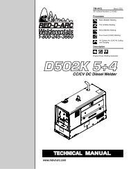
ELECTRICELECTRICELECTRICELECTRICA-2PRODUCT DESCRIPTIONThe <strong>MX350</strong> converter (K1823-1) is part of a Multi-Weld system, ideally suited for construction site welding,which uses a single DC power source, as the onlyINSTALLATIONA-2input supply, and provides independent full range controlof up to 350A continuous with each converter arcfor + polarity stick and wire processes, as well as forarc-air gouging.(See Figure 1).MULTI-WELD SYSTEMLINCOLN ®ELECTRICCONVERTERLINCOLN ® MULTI-WELD350350 340WIRELINCOLNELECTRIC®MULTI-WELD 350LINCOLN ®ELECTRICLN-25WIRE FEEDERMULTI-SOURCEMULTI-SOURCELINCOLN ®ELECTRICLINCOLN ® MULTI-SOURCEELECTRICDISTRIBUTIONBOXLINCOLN ® MULTI-WELD350350 340STICKCONVERTERLINCOLNELECTRIC®MULTI-WELD 350LINCOLN ® MULTI-WELD700 AMP <strong>ARC</strong> GOUGE350350 340LINCOLN ® MULTI-WELD350350 340LINCOLNELECTRIC®MULTI-WELD 350PARALLELCONVERTERSLINCOLNELECTRIC®MULTI-WELD 350Figure 1The <strong>MX350</strong> is a DC to DC converter which convertshigher voltage/lower current input power to lower voltage/highercurrent output power with over 90% efficiency.For example; a single 600A continuous rated 70-80vpower source could supply up to five <strong>MX350</strong> converterseach wire welding at 300 amps, or about ten convertersfor stick welding at 150 amps, with 26-29v atthe arcs.The Arc Converter is a single "world" model built toIEC and CSA standards and meeting the specificneeds inherent to construction site welding:Versatile• Constant Current (CC) mode for stick and gouging.Includes Hot Start and Arc Force controls to optimizeCC performance, and can be paralleled forhigher capacity welding and arc gouging.• Constant Voltage (CV) mode for positive polaritycored and solid wire welding with arc-poweredfeeders (such as the LN-25).Portable• Arcs can be moved quickly with the light weightConverter that’s easy to carry, or pull, and is smallenough to fit through a 15" (38cm) diameter or 12"x 16" (31x 41cm) elliptical man-hole.• Converter is powered by the welding cable fromthe DC power source, without the safety hazard ofhigh AC input supply voltages.<strong>MX350</strong>
A-3• Converter welding controls are near the arc withoutlong control cables, and a receptacle is providedfor an optional remote for even closer user outputcontrol.Simple• Easy installation with 10 ft. (3m) work clip lead anduser preference quick-connect "pigtails" for inputand electrode weld cables.• Easy setup with only a few intuitive welding controlsand lit displays; including a singlePower/Mode switch with Input level light, and asingle presettable Output Control with separatedigital meters for Amps and Volts, featuring postweldfive second memory display.INSTALLATIONA-3RECOMMENDED EQUIPMENT ANDPROCESSESMULTI-SYSTEM POWER SOURCEThe Multi-Source 40KW 80VDC buss power source(K1752-1) is recommended for use in the Multi-Weldsystem. However, other DC power sources capable ofsupplying the required system buss current, at above60 volts, may be used. It is recommended that thispower source have lower output inductance (choke)such as the Lincoln Electric DC-1000, DC-655 or DC-600 set for max. output in CC mode. The powersource output VA capacity should be 10% greaterthan the sum of the max. VA of the converter arcswhich may all be simultaneously welding or gouging:• Easy Service with quick to replace cable "pigtails"and"plug-in" assembly modules, includingaccessible PC boards and interchangeable "plugn-play"panel instruments.Robust• Capacity is rated for continuous operation at 350amps in 50°C (122°F) ambient temperature, andcan be paralleled to multiply CC mode output rating.• Overload protection is provided with electronic limitingof output current, and with thermostat andover-voltage shutdown protection which automaticallyreset.• Outdoor operation protected with sealed controland power electronics compartments, with sealedinterconnections, housing "potted" circuit boards,and using "Central-Air" cooling with "Fan-As-Needed" for less dirt intake.• Handling (and mishandling protection) is enhancedwith light, but durably designed, aluminum constructionwith front to back, top and bottom, handles(also serving as "roll bar" and skid), and asheetmetal shell attached with 1/4" steel threadedfasteners. The strength can easily support a 250lb. man jumping on the case.Power Source (Volts x Amps) capacity > 1.1 x Sumof Converters’ (Volts x Amps) arcsDISTRIBUTION BOXThe Multi-Weld Distribution Box (K1736-1) is availablefor interconnection of the Multi-System using thesame "pig-tail" connection method provided with the<strong>MX350</strong> converter. Six cable strain-relief ports are providedfor connection of up to (12) cables for distributionor "daisy-chain" inter-connection to other boxes.Four "pig-tail" leads (see below) are included with theBox."PIG-TAIL" LEADS AND CONNECTORSAccessory "pig-tail" leads and Twist-Mate connectorsare available from Lincoln for extra connections to the<strong>MX350</strong> or the Distribution Box:Order No.CL012705Description:22in.(56cm) long 2/0 (70mm2) cablewith 0.5in.(13mm) hole lug and cut-offends.K852-70 Twist-Mate male insulated plug for1/0-2/0 (50-70mm2) cable.K852-95 Twist-Mate male insulated plug for2/0-3/0 (70-95mm2) cable.K1759-70 Twist-Mate female insulated receptaclefor 1/0-2/0 (50-70mm2) cable.K1759-95 Twist-Mate female insulated receptaclefor 2/0-3/0 (70-95mm2) cable.<strong>MX350</strong>
A-4REMOTE OUTPUT CONTROL OPTIONSThe <strong>MX350</strong> is provided with a 3-pin remote receptacle.CV MODE WIRE WELDINGThe Converter in CV mode was designed for use withan arc-powered wire feeder like the LN-25. TheConverter output is always "hot" when the modeswitch is not OFF, so it is recommended that the LN-25 model be equipped with the internal contactor inorder to have a "cold" electrode when the gun triggeris released.The CV mode recommended processes are positive(+) polarity wire welding within the output capacity ofthe Converter, including:Flux Cored Arc Welding (FCAW)Innershield: NS3M (5/64-3/32)NR305 (.068)Outershield: OS-70 (1/16-5/64)OS-71 (.045-1/16)Gas Metal Arc Welding (GMAW)MC-710 (.045-5/64)Carbon Steel: L50/56 (.030-1/16)INSTALLATIONArc Air Carbon (AAC)INSTALLATIONGouging: Carbons (5/32-3/8)QUICK-CONNECT "PIG-TAILS"A-4The <strong>MX350</strong> is factory provided with two 21 in.(53 cm)long 2/0 AWG (70mm2 ) "pig-tail" cables with their0.5"(13mm) hole lug ends routed through the "INPUT+ "(on back) and "ELECTRODE + "(on front) cablechannels of the Converter and attached to the bottomaccessedcovered cable connection studs.Attach the preferred standard user-provided Quickconnectterminal (such as Lincoln Twist-Mate orTweco 2-MPC type) to the cut-off end of these cables.Use the female connector on the "ELECTRODE +"cable and the male connector on the "INPUT +" cable.CC MODE STICKGOUGINGWELDING ANDThe CC mode recommended processes are positive(+) polarity stick and arc gouging within the outputcapacity of single, or paralleled, Converters; including:Shielded Metal Arc Welding (SMAW)E6010/6011: FW5P/180 (3/32-1/4) "fast-freeze"E6013: FW37 (3/32-3/16)"fill-freeze"E7010/8010: SA85/70+ (3/32-7/32)"fast-freeze" HT pipeE7018/7028: JW LH70/3800 (3/32-5/32) "low-hydrogen"E7024/6027: JW1,3/2 (1/8-5/16)"fast-fill"<strong>MX350</strong>
INPUTELECTRODEA-5ATTACHMENT AND ARRANGEMENT OF"PIG-TAILS"To best suit the desired inter-connection of theConverters the "pig-tail" cables may be routed into thefront cable channels, and/or into the back for single ordouble "pig-tail" cables to the bottom-accessed coveredcable connection studs. (See below and refer toFigures 1 and 2.):IN+TO POWERSOURCE+TOWORK+TO ELECT.ELECT.+INSTALLATIONA-53. Slip the "pig-tail" cable lug(s) over the stud andre-secure the flange nut, making sure that lug(s)nowhere touch any sheetmetal of the stud housing,then fold back the cover insulation andreplace the stud cover.WARNINGBe sure to follow the safety practice to usethe female connector on the cable whichwould normally be electrically "hot" (supplylead) if disconnected when the system isenergized, and the male on the normally"cold" (load lead) side. If practical, shut offpower before connecting or disconnecting terminals.------------------------------------------------------------------------WORK CONNECTIONEach Converter in the Multi-Weld System must have itsindividual “Work” lead connected (clipped) to work. The#3 AWG (27mm 2 ) Work clip lead must have clean metalconnection to the work to complete the DC input supplyand output power circuits of the <strong>MX350</strong>.WARNINGIN+TO POWERSOURCEBOTTOM VIEWTO ELECT.ELECT.+To connect the "pig-tail" cables to the Converter:1. Stand the Converter vertically on its rear handleand skid to gain access to the bottom stud covers,then remove the two 0.25"(6.3mm) screwssecuring each cover and fold out the cover insulation.2. Route the appropriate "pig-tail" cable lug endsunder the skid rail (for strain-relief) through thedesired front and/or rear corner channels to theexposed 0.5"(13mm) stud, and remove the flangenut with a .75"(19mm) wrench. Note: Input supplycable(s) must connect through "INPUT +" labeledchannels, and output weld cable(s) must connectthrough "ELECTRODE +" labeled channels.Do not disconnect the Work clip lead without firstswitching OFF the Converter panel switch. Failure todo so will allow the work lead clip to be electrically"hot" to work, and "hot" to the electrode, through thecircuit of the Converter for about 5 seconds until theinput contactor opens.------------------------------------------------------------------------CASE GROUNDINGAs shipped, the case of the <strong>MX350</strong> is isolated from allof the DC input and output welding terminals, and isequipped with a grounding terminal screw (.31” /7.9mm) marked with the symbol located on thebottom rear of the Base assembly. ( Refer to the bottomview figure.) In order to comply with CSA and ULcase grounding specifications, this terminal is providedfor connection to weldment work which must beproperly grounded per methods meeting local andnational electrical codes. Refer to “Saftey in Welding,Cutting and Allied Processes”, ANSI Z49.1 (US) andW117.2 (Canada).Since any case fault would only involve the DC weldingcircuit, the size of the grounding lead should havethe capacity to ground the potential fault current withoutburning open. Use at least #6AWG (13mm 2 ), butneed not exceed the size of the input cable supplingthew <strong>MX350</strong>.Connect the Multi-Weld grounding lead to the workpiece separately from the Work clip. If the same clip isused for both ground and work connection, the Multi-Weld case will be electrically “hot” to the work if theclip is removed without first switching OFF the panelswitch. ( Refer to the Work clip WARNING above).<strong>MX350</strong>
B-2Average Amps for about 7 seconds after weldingstops in CC and CV modes only.•The 5 second memory display is indicated bythe display’s left-most decimal point blinking,and is interrupted if arc is restarted.Accuracy of Actual Amps is within 3%, and typicallywithin 10 amps of Preset.•An Actual Amps meter calibration adjustmenttrimmer is provided. ( See MAINTENANCEsection).Two front screws secure the meter bezel whichholds a replaceable spatter shield lens (Lincolnpart no. T14807-9).(4) VOLTS Digital Meter is a 3-1/2 digit LED meterwhich displays:Preset Volts in CV mode when not welding."Blank" in CC mode when not welding.Actual Volts while welding in both CV and CCmodes.Average Volts for about 7 seconds after weldingstops in CV and CC modes only.•The 7 second memory display is indicated bythe display’s left-most decimal point blinking,and is interrupted if arc is restarted.Accuracy of Actual Volts is within 3%, and typicallywithin 1 volt of Preset.•An Actual Amps meter calibration adjustmenttrimmer is provided. ( See MAINTENANCEsection).Two front screws secure the meter bezel whichholds a replaceable spatter shield lens.(5) Thermal Shutdown (yellow) Light turns on ifoutput is shutdown because internal overheatinghas occurred. (See OVER TEMPERATURESHUTDOWN in this section).(6) Input Voltage (green) Light indicates appropriatelevel of input supply voltage:"On" for adequate input voltage over 50v for CCor CV mode."Off" for inadequate input voltage under 50v, noinput or Power Switch OFF.Note: If green light is "blinking" the input voltage maybe drifting above and below the 50 V level due toloads on supply and cables. This may also cause theinput contactor to “chatter”.OPERATION<strong>MX350</strong>B-2RECESSED PANEL CONTROLSThese instruments are recessed behind a screwsecured hinged cover panel, and are not typicallyrequired for normal operator access. They may be leftcovered, as factory set, or setup as desired with orwithout the hinged cover secured:(7) Hot Start Control is provided to enhance arc startingin both CC and CV modes with an extra output"boost" at the arc strike that returns to the settinglevel in less than a second (about 0.30 sec. in CCmode, and 0.045 sec. in CV mode). This extra HotStart amplitude is adjustable from "0" (no extra) to"10" (100% of setting extra), with the factory set "5"(center) position typically good for most weld starting.However, “0” may provide smoother starting for finewire CV MIG.(8) Arc Force Control is only functional in the CCmode with Stick/Gouge slope. (See below). ArcForce prevents "stubbing" of the electrode by providingextra weld current if the arc voltagedrops below about 14v. This extra weld current isadjustable from "-10" (no extra) to "+10" (60% ofsetting extra), with the factory set "0" (center) positiontypically good for most welding.(9) CC Slope Switch is provided to enhance stickwelding on "fast-freeze" type electrodes (such asE6010 and E7010) typically used on pipe weldingapplications for fast root pass vertical down "drag"technique (not "whipping"). If using this type ofapplication improved operating appeal may beobtained if the CC Slope is switched from the factoryset STICK / GOUGE position to the PIPEposition.Note: The PIPE position uses a "drooping" typeslope (~22v/100A), so preset current (not actualcurrent) accuracy may be affected if arc lengthvoltage is not maintained at the typical 28v usedfor these electrodes. Typically this error should notbe more than about 10 A.(10) Remote Control Receptacle is provided to permitthe use of an optional Remote output controlto provide operator control even closer to the arc.Connecting the Remote’s plug to this receptacleautomatically transfers output control from thepanel Output Control (item (2) above) to theRemote pot control, which will function the same,but with only single-turn resolution.Disconnecting the Remote’s plug from this receptacleautomatically transfers output control backto the panel Output Control (item (2) above).
B-3PARALLELED CONVERTERS<strong>MX350</strong> converters that are paralleled (see INTER-CONNECTION OF CONVERTERS in the INSTALLA-TION section) must each be set up in the same mannerin order to manage the arc current drawn fromeach:1) Set to CC mode with CC SLOPE switch set toSTICK/GOUGE.2) Preset Output Controls of both paralleledConverters to ~1/2 desired total Amps.If arc current from each Converter gets too out of balance(primarily a problem if trying to use CV mode)the hotter running Converter could go into current-limitingand/or Thermal shutdown (See OVER-TEMPER-ATURE SHUTDOWN in the INSTALLATION section),which might then overload the other, or at least interruptthe operator’s process. However, no damage willoccur to the Converters.REMOTE CONTROL OFPARALLELED CONVERTERS(FOR CC STICK/GOUGE MODE ONLY)Full Range remote control can be accomplished with aseparate optional Remote output control (seeINSTALLATION section) connected to eachConverter. The current contribution of each Converterwill depend on its remote output setting.Partial Range remote control can be accomplishedwith a single Remote Control connected to the outputConverter with the input Converter preset with itspanel Output Control to below the minimum desiredoutput range. The Remote Control, connected to theoutput Converter, will control its output to add to thepreset level.OPERATIONTRANSPORTING AND STORAGEOF THE <strong>MX350</strong>CABLE HANDLINGThe input and electrode cables are easily disconnectedfrom the quick-connect "pig-tails", and the Worklead can be reeled around the <strong>MX350</strong> case cradled bythe base skid handles, to which the clip can besecured.TRANSPORTINGThe Converter may be carried by one or two personsusing the front and rear top and bottom handles. It canalso be set vertically on a two wheel cart, or horizontallyon a wagon, to convey it longer distances.STORAGEThe <strong>MX350</strong> may be set on a floor, or shelf, horizontallyon its skid, or vertically standing on its rear top andbottom handles.PROTECTION FEATURESThe <strong>MX350</strong> design features electronic protection systemsto help assure reliable operation even underadverse conditions. These systems include:FAN AS NEEDED (F.A.N.)The cooling fan will turn on when the arc starts andremain on for about a minute after the arc is out tocool down the power components.This feature electronically controls the fan so it doesnot run continuously when the power switch is turnedon. This will minimize the amount of contaminate andclogging debris which may be drawn into theConverter, in addition to the "Central-Air" systemdesign which intakes lower velocity air through thehigher side louvers and blows out through the lowerback louvers with higher velocity.OVER-VOLTAGE PROTECTIONThe <strong>MX350</strong> input contactor will open if the input supplyvoltage is above 113VDC, and will automaticallyreclose if the voltage drops back below. During Over-Voltage Shutdown the panel displays will be as appropriatefor the non-welding mode. (See FRONT PANELCONTROLS in this section).CAUTIONB-3When the contactor recloses the output of theConverter will reactivate. Switching OFF input powerprevents unexpected reactivation.------------------------------------------------------------------------This feature protects internal components of theConverter from excessive voltage levels.<strong>MX350</strong>
B-4OVER-CURRENT PROTECTIONThe max. output current of the <strong>MX350</strong> is electronicallylimited, to protect internal power components, so asnot to exceed about 375 amps average and 500 ampspeak. When the current load starts to exceed theselimits the output is reduced (lower voltage) to sustainthese max. levels, until the current is reduced. even toa shorted output.OPERATIONB-4Prolonged output at this max. current limit level mayeventually overheat the Converter’s internal powercomponents causing over-temperature shutdown.(See following section).Short circuit protection is also provided to reduce max.output current to about 200 amps if the output voltageis reduced, by loading or current limiting (see above),to below 14 volts for over 7 seconds (indicating ashorted output). The output current must be interruptedto reset this reduced protective level.This max. 200 amp short circuit level will allow usingthe <strong>MX350</strong> for "pipe-thawing" applications withoutcausing over-temperature shutdown. (See followingsection).OVER-TEMPERATURE SHUTDOWNA second over-load protection switch in the ImbalanceProtector Module was added to <strong>MX350</strong> models withcodes 10736, and higher. This module senses for animbalance of current between the paralleled Chopperboards by sensing the differential choke voltage. If thisvoltage exceeds 1v for a sustained time theImbalance Protector will also activate over-temperatureshut down to protect the higher current Chopperboard from over heating.CAUTIONWhen the thermostat resets the output of theConverter will reactivate. Switching OFF input powerprevents reactivation, but also shuts off the coolingfan which prolongs the reset time.------------------------------------------------------------------------During Over-Temperature Shutdown the panel displayswill be as appropriate for the non-welding mode.(See FRONT PANEL CONTROLS in this section),except the fan will remain running and the ThermalShutdown (yellow) Light will be lit until reset. Typically,If shutdown occurs repeatedly below 300 amps outputwith fan running, imbalance of the Chopper board currentmay likely be the cause.<strong>MX350</strong>
C-1SAFETY PRECAUTIONSWARNINGHave qualified personnel do the maintenancework.Always use the greatest care when working nearmoving parts.MAINTENANCEC-13. Holding the unit by the front handles, so the back isfacing down, shake the loose debris out of the unit.Raking out the heatsink fins may be necessary forjammed debris.4. If necessary, remove the case wraparound coverand using the skid handles to hold upside downcarefully dump out any remaining loose debris,or carefully blow out using low pressure air.If a problem cannot be corrected by following theinstructions, take the machine to the nearestLincoln Field Service Shop.-----------------------------------------------------------------------ELECTRIC SHOCK can kill.• Do not touch electrically live parts orelectrode with skin or wet clothing.• Insulate yourself from work andground• Always wear dry insulating gloves.------------------------------------------------------------------------See additional warning informationthroughout this operator’s manual andthe Engine manual as well.-----------------------------------------------------------MAINTENANCEThe only maintenance which may be required for the<strong>MX350</strong> is to clean out any accumulated dirt and debriswhich could contaminate internal components, orobstruct proper cooling of the power componentsresulting in premature over-temperature shutdown.The recommended cleaning procedure is as follows:1. Be sure to disconnect the Converter’s inputcable to remove its input power.2. Remove the four screws securing the rear louverpanel, and remove the panel to expose the coolingtunnel heatsinks. (See Figure 4 below):5. Reassemble the cleaned out Converter byreversing the above steps.DIGITAL METER CALIBRATIONIf calibration of either digital meter is ever necessary,meter calibration adjustment trimmers are provided onthe Weld Control PC board inside the Control Module(see Figure 5). Calibration must be done with anOutput current load, so meters are displaying Actual(not Preset) values. It is recommended that the calibrationlevels be near the rating plate values, for bestaccuracy, and compared to "master" meters with betterthan 2% accuracy.The accuracy of Actual AMPS meter should be within3% of the welding amps monitored. The AMPS metertrimmer (R561) is located near the center of the WeldControl PC board just below the VOLTS meter trimmer(R562). Clockwise rotation of the trimmer adjustmentscrew will decrease the meter reading.The accuracy of Actual VOLTS meter should be within3% of the welding volts monitored. The VOLTS metertrimmer (R562) is located near the center of the WeldControl PC board just above the AMPS meter trimmer(R561). Clockwise rotation of the trimmer adjustmentscrew will decrease the meter reading. The"master" voltmeter should be connected as close aspossible to the "ELECTRODE +" stud and "WORK-"lead bolt, for best accuracy.Figure 4<strong>MX350</strong>
C-2SERVICEThe <strong>MX350</strong> was designed for easy service usingquick to replace components, and assembly modulesMAINTENANCEC-2which could be simply swapped out at the job site tominimize down time, and so more prolonged troubleshootingand repair of the module may be donelater on the service bench.4213Figure 5The above, Figure 5, shows the three assembly modules of the Converter which are covered with the CaseWraparound (item (4)):Control Module (item (1) is removed from the BaseModule assembly by removing the two bottomaccessed screws and disconnecting the three sealedharness plugs from the receptacles on the back of theControl box.This module is a sealed enclosure containing replaceableelectronic components:•Sealed back cover which mounts the internal "potted"Control and Peripheral PCB’s.•Front panel with "plug-n-play" instruments whichindividually plug to the Control PCB.•Interchangeable "potted" digital meters with frontreplaceable spatter shield lenses.•Harness lead receptacles that connect to BaseModule harness lead plugs.Tunnel Module (item (2) is removed from the BaseModule assembly by removing the four bottomaccessed screws and disconnecting the two sealedharness plugs and power leads.Note: Removal of Control Module improves access todisconnect Tunnel Module power leads.<strong>MX350</strong>This module assembly includes:•Heatsinked power switching (IGBT) boards and isolateddiodes.•Capacitors and potted power supply boards.•Fan and sheetmetal bulkhead tunnel and componentenclosure.•Harness lead receptacles and power leads that connectto Base Module.Base Module (item (3) is the mounting and connectionplatform for the other modules.This module assembly includes:•Base sheetmetal with input / output connectionchambers with "pigtail" leads.•Input contactor, input diodes heat sink assemblyand work clip lead.•Output chokes and current shunt.•Lead harness sealed plugs connect to Tunnel andControl Module receptacles.
D-1TROUBLESHOOTINGD-1HOW TO USE TROUBLESHOOTING GUIDEWARNINGService and Repair should only be performed by Factory Trained Personnel. Unauthorizedrepairs performed on this equipment may result in danger to the technician and machineoperator and will invalidate your factory warranty. For your safety and to avoid ElectricalShock, please observe all safety notes and precautions detailed throughout thismanual.__________________________________________________________________________This Troubleshooting Guide is provided tohelp you locate and repair possible machinemalfunctions. Simply follow the three-stepprocedure listed below.Step 1. LOCATE PROBLEM (SYMPTOM).Look under the column labeled “PROBLEM(SYMPTOMS)”. This column describes possiblesymptoms that the machine mayexhibit. Find the listing that best describesthe symptom that the machine is exhibiting.Step 2. POSSIBLE CAUSE.The second column labeled “POSSIBLECAUSE” lists the obvious external possibilitiesthat may contribute to the machinesymptom.Step 3. RECOMMENDED COURSE OFACTIONThis column provides a course of action forthe Possible Cause, generally it states tocontact your local Authorized Field ServiceFacility.If you do not understand or are unable toperform the Recommended Course ofAction safely, contact your local AuthorizedField Service Facility.CAUTIONIf for any reason you do not understand the test procedures or are unable to perform the tests/repairs safely, contact yourLocal Authorized Field Service Facility for technical troubleshooting assistance before you proceed.<strong>MX350</strong>
D-2PROBLEMS(SYMPTOMS)Machine completely dead:Input contactor does not pull in,meters are off.TROUBLESHOOTINGObserve all Safety Guidelines detailed throughout this manualPOSSIBLE AREAS OFMISADJUSTMENT(S)1. Check cable connections from (+)Input and Work to power sourcefor loose or faulty connection.2. Input voltage may be too low.Measure input voltage tomachine, should be 50 – 113VDC.3. The power switch may be faulty.4. The DC Buss Power Supply PCBor its connections may be faulty.5. The Analog Control Power SupplyPCB may be faulty.6. The Weld Control PCB may befaulty.RECOMMENDEDCOURSE OF ACTIOND-2Meter turns on but input contatordoes not pull in.Machine has no output:1. Check input voltage, should beless than 113 VDC.2. Remote receptacle output switchingenabled. Check if jumper isopen on plug P21. (Refer to wiringdiagram).If all recommended possible areas ofmisadjustment have been checkedand the problem persists, Contactyour local Authorized FieldService Facility.3. The contactor or supply voltage tocontactor coil may be faulty.4. The connections at PCB connectorsinside the control box may befaulty.5. The Peripheral PCB may befaulty.6. The Weld Control PCB may befaulty.Thermal light comes on.No output:1. Thermal shut down. Wait untilmachine cools down and thermallight goes out. Do not overloadmachine.2. The thermostat or imbalance protector(if present) or their connectionsmay be faulty.CAUTIONIf for any reason you do not understand the test procedures or are unable to perform the tests/repairs safely, contact yourLocal Authorized Field Service Facility for technical troubleshooting assistance before you proceed.<strong>MX350</strong>
D-3TROUBLESHOOTINGObserve all Safety Guidelines detailed throughout this manualPROBLEMSPOSSIBLE AREAS OF RECOMMENDED(SYMPTOMS)MISADJUSTMENT(S) COURSE OF ACTIONMeter turns on, input contactor 1. The output cable connections maypulls in, thermal light is off. be faulty. Check (+) ElectrodeMachine has no output:and Work cable connections.2. The connections at control boxplugs, chopper boards plugs, orAnalog Control Power Supply PCBconnectors may be faulty.3. Inputs to Chopper PCB orChopper PCB may be faulty.4. The Analog Control Supply PCBmay be faulty.5. The connection at PCB connectorsinside the control box may befaulty.6. The Weld Control PCB may befaulty.D-3Preset is not adjustable:Note: Panel control is disabled ifRemote is plugged in.Preset range is not right:1. The output control potentiometeror its connections may be faulty.2. The Weld Control board or its connectionsmay be faulty.1. A faulty or missing plug P3 at connectorJ3 of Weld Control PCB.If all recommended possible areasof misadjustment have beenchecked and the problem persists,Contact your local AuthorizedField Service Facility.2. The Weld Control board or its connectionsmay be faulty.None of the meters comes on inCC or CV settings:1. The Analog Control Power SupplyPCB or its connections may befaulty.2. The Weld Control PCB or connectionsto meters may be faulty.3. Faulty meters.Meter comes on in only one of theCC or CV settings:1. The Weld Control PCB or connectionsto meters may be faulty.2. Faulty meters.CAUTIONIf for any reason you do not understand the test procedures or are unable to perform the tests/repairs safely, contact yourLocal Authorized Field Service Facility for technical troubleshooting assistance before you proceed.<strong>MX350</strong>
D-4PROBLEMS(SYMPTOMS)The meter is not accurate:TROUBLESHOOTINGObserve all Safety Guidelines detailed throughout this manualPOSSIBLE AREAS OFMISADJUSTMENT(S)1. The Analog Control Power SupplyPCB or its connections may befaulty.2. The Weld Control PCB may befaulty.RECOMMENDEDCOURSE OF ACTIOND-4Fan does not run when turningmachine on:Fan does not run when welding:1. Fan does not normally run untilmachine is welding. SeeInstruction Manual.1. Faulty Supply voltage to fan, normalis 40 VDC.2. Replace fan if supply voltage tofan is good.3. The Weld Control PCB may befaulty.If all recommended possible areas ofmisadjustment have been checkedand the problem persists, Contactyour local Authorized FieldService Facility.No control, very high output current:1. Check input & output cables.Check connections at (+) Inputstud & (+) Electrode stud, makesure they don’t short to case.2. Faulty shunt lead connection.3. Faulty output control potentiometeror its connections.4. Faulty Weld Control PCB.No control, maximum output currentstays around 200A:1. Check output cables. Check connectionsat (+) Electrode stud andWork.2. Faulty voltage feedback connection.Check continuity from lead#401 at C1 to lead #301 at pin 1of P22 (refer to wiring diagram).3. Faulty Weld Control PCB.No control :1. Faulty output control potentiometeror its connections.2. Faulty connections at WeldControl PCB connectors.3. Faulty Weld Control PCB.CAUTIONIf for any reason you do not understand the test procedures or are unable to perform the tests/repairs safely, contact yourLocal Authorized Field Service Facility for technical troubleshooting assistance before you proceed.<strong>MX350</strong>
D-5PROBLEMS(SYMPTOMS)Current changing with arc lengthin Stick welding:TROUBLESHOOTINGObserve all Safety Guidelines detailed throughout this manualPOSSIBLE AREAS OFMISADJUSTMENT(S)1. Check the CC Slope switch on therecessed panel, it should be set atStick/Gauge position for Stickwelding.2. Faulty CC Slope switch or connections.3. Faulty Weld Control PCB.RECOMMENDEDCOURSE OF ACTIOND-5Poor performance on "fast-freeze"type electrodes such as E6010,E7010:1. Check the CC Slope switch on therecessed panel, it should be set atPipe position.Bad starting:Electrode "stubbing":2. Faulty CC Slope switch or connections.3. Faulty connections on WeldControl PCB connectors.4. Faulty Weld Control PCB.1. Adjust Hot Start setting on therecessed panel.2. Check Hot Start potentiometerand connections. The Hot Startand Arc Force potentiometers areinterchangeable, switch them tocheck out.1. Adjust Arc Force setting on therecessed panel.2. Check Arc Force potentiometerand connections. The Hot Startand Arc Force potentiometers areinterchangeable, switch them tocheck out.If all recommended possible areas ofmisadjustment have been checkedand the problem persists, Contactyour local Authorized FieldService Facility.CAUTIONIf for any reason you do not understand the test procedures or are unable to perform the tests/repairs safely, contact yourLocal Authorized Field Service Facility for technical troubleshooting assistance before you proceed.<strong>MX350</strong>
E-1DIAGRAMSE-1ON/OFF & MODE SELECTS1202ACC CVOFF202231219REMOTE RECEPTACLE<strong>ARC</strong> FORCER3STICK/GOUGES2CC SLOPEX4 C1P45 X4A C25 6 8 7 9 1 3 2 4INPUT CAPACITORJ45(LEFT)INPUT CAPACITOR(RIGHT)REVERSEDIODED5D4CHOPPER PCB(LEFT)CHOPPER PCB(RIGHT)HEATSINKCONNECTION(LEFT)HEATSINKCONNECTION (RIGHT)L1 L2217218+222223A AB BPIPEC CINPUT CONTACTOR-217221INPUT DIODESFREE WHEELINGDIODES (LEFT)FREE WHEELINGDIODES (RIGHT)AMPPL1 PL2OUTPUT CONTROLR1COVE<strong>RED</strong> PANEL(VIEWED FROMREAR)PCB CONNECTOR CAVITY NUMBERING SEQUENCE(VIEWED FROM COMPONENT SIDE OF P.C. BOARD)342 PIN 4 PINJ6 J7, J8, J9J41, J46<strong>MX350</strong> WIRING DIAGRAMJ21PANEL RECEPTACLESPERIPHERAL PCBR 413414440POWER SUPPLY PCBDC BUSS POWER SUPPY PCB201202230204231206207208327R 326301302330304331306307308300R 313314R 315316309310311312R 313314R 315316309310311312301302303304308J31 J32J30J42J41408409411412410439438441440442J46J47224237230201238234204208209210211212R 413414R 415416408J45AJ6 J4 J11 J2J10J1HOT START <strong>ARC</strong> FORCEKEY PINJ8 J9J12 J13X1AOUTPUT CHOKE (LEFT) OUTPUT CHOKE (RIGHT)X1200216R 215214R 213209212210211R 226227206207R 226227200R 213214R 215216409410411412401402403404437436402404403436442437401A401401A236+OUTPUTWELD CONTROL PCBCONTROL303303A FAN300330237238234A236CR1 CR1(+) INPUTX4 X4AGENERAL INFORMATIONELECTRICAL SYMBOLS PER E1537(-) INPUT / WORKRESISTORS = OHMS/WATT UNLESS OTHERWISE SPECIFIEDALL SWITCH WIRING VIEWED FROM REAR OF SWITCHIMBALANCE PROTECTORNOTE: SINCE COMPONENTS OR CIRCUITRY OF A PRINTED CIRCUIT BOARDMAY CHANGE WITHOUT AFFECTING THE INTERCHANGEABILITY OF ACOMPLETE BOARD. THIS DIAGRAM MAY NOT SHOW THE EXACT COMPONENTSOR CIRCUITRY OF CONTROLS HAVING A COMMON CODE NUMBER.R 32632750 mV/400ASHUNTBP4 CASE(+) ELECTRODE10-2000DG3943M1M2M3M4M5M6M9M10M1M6M2M3M4M9M5M10M1M6M2M3M4M9M5M10234AVOLTJ5M1M2M3M4M5M6M9M10224234202BHIWIPERLO219221218CBA223222202BD3E3LOHI WIPERHOT STARTR2L6L7L4L5L9L8L3J7MAXVARMINMAXVARMIN331VARMINMAXVARMINMAXINPUTINDICATORLIGHTTHERMALLIGHT1 2 1 3 1 4 1 5 1 84 6 5 8 6 10 9 166 PIN 8 PIN10 PIN16 PINJ10, J11, J45 J2, J3 J4, J5, J42 J12, J31J13, J47CONTROL BOXBACK PANEL(VIEWED FROM PCB SIDE)TUNNEL ASSEMBLY(VIEWED FROM PCB SIDE)BY-PASS PCBPANEL RECEPTACLE CAVITY NUMBERING SEQUENCE(VIEWED FROM LEAD SIDE OF RECEPTACLE)L3 THROUGH L10: RF CHOKESR1: 10K, MULTI-TURNR2, R3: 10K, ONE TURN303A12<strong>RED</strong> LEADB7B3B1B2B1B2B7B3441438439R 415416ANALOG CONTROLKEY PINKEY PINKEY PINCONTROL BOXFRONT PANEL(VIEWED FROM REAR)TIN TERMINALL10PANEL PLUGSP211 2 3 4P221 2 3 4 5 6 7 8 9 1 2 3 4 5 6 7 8 9J22P23J231 2 3 4 5 6 7 8 9P24J241 2 3 4 5 6 7 8 9PANEL PLUGSP20J20PANEL RECEPTACLES+X1 + X1AP45A5 6 8 1 3 7 9 2 4REVERSEDIODED6J3D1 D2BP5BP24 PINJ216 5 49 8 79 PINJ20, J22, J23,J24, J45, J45A4 PINP214 5 67 8 99 PINP20,P22, P23,P24,P45, P45ANOTES:N.B. R-XXX DENOTES A <strong>RED</strong> LEAD NUMBE<strong>RED</strong> XXXTHERMOSTAT306307BP3BP1GROUNDINGSCREW31423212143123<strong>MX350</strong>
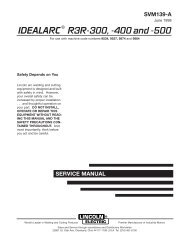
AE-2DIAGRAMSE-2DIMENSION PRINT - <strong>MX350</strong> CONVERTER11321<strong>MX350</strong>
E-3DIAGRAMSE-3DIMENSION PRINT FOR DISTRIBUTION BOXM19448C-UF<strong>MX350</strong>
NOTES<strong>MX350</strong>
NOTES<strong>MX350</strong>
AMERICAN EXPRESSAMERICAN EXPRESS®Now Available...12th EditionThe Procedure Handbook of Arc WeldingWith over 500,000 copies of previous editions publishedsince 1933, the Procedure Handbook is considered by many tobe the “Bible” of the arc welding industry.This printing will go fast so don’t delay. Place yourorder now using the coupon below.The hardbound book contains over 750 pages of weldinginformation, techniques and procedures. Much of this materialhas never been included in any other book.A must for all welders, supervisors, engineers anddesigners. Many welding instructors will want to use the bookas a reference for all students by taking advantage of the lowquantity discount prices which include shipping by4th class parcel post.$15.00 postage paid U.S.A. MainlandHow To Read Shop DrawingsThe book contains the latest information and applicationdata on the American Welding Society Standard WeldingSymbols. Detailed discussion tells how engineers anddraftsmen use the “short-cut” language of symbols to passon assembly and welding information to shop personnel.New Lessons in Arc WeldingLessons, simply written, cover manipulatory techniques;machine and electrode characteristics; related subjects,such as distortion; and supplemental information on arcwelding applications, speeds and costs. Practice materials,exercises, questions and answers are suggested for eachlesson.528 pages, well illustrated, 6” x 9” size, bound in simulated,gold embossed leather.$5.00 postage paid U.S.A. MainlandNeed Welding Training?The Lincoln Electric Company operates the oldest andmost respected Arc Welding School in the United States at itscorporate headquarters in Cleveland, Ohio. Over 100,000 studentshave graduated. Tuition is low and the training is“hands on”For details write:Lincoln Welding School22801 St. Clair Ave.Cleveland, Ohio 44117-1199.Practical exercises and examples develop the reader’s abilityto visualize mechanically drawn objects as they will appearin their assembled form.187 pages with more than 100 illustrations. Size 8-1/2” x 11”Durable, cloth-covered board binding.$4.50 postage paid U.S.A. Mainlandand ask for bulletin ED-80 or call 216-383-2259 and ask for theWelding School Registrar.Lincoln Welding SchoolBASIC COURSE $700.005 weeks of fundamentalsThere is a 10% discount on all orders of $50.00 or more for shipment at one time to one location.Orders of $50 or less before discount or orders outside of North America must be prepaid with charge, check or money order in U.S. Funds Only.Prices include shipment by 4 th Class Book Rate for U.S.A. Mainland Only. Please allow up to 4 weeks for delivery.UPS Shipping for North America Only. All prepaid orders that request UPS shipment please add:$5.00 For order value up to $49.99$10.00 For order value between $50.00 & $99.99$15.00 For order value between $100.00 & $149.00For North America invoiced orders over $50.00 & credit card orders, if UPS is requested, it will be invoiced or charged to you at cost.Outside U.S.A. Mainland order must be prepaid in U.S. Funds. Please add $2.00 per book for surface mail or $15.00 per book for air parcel post shipment.METHOD OF PAYMENT: (Sorry, No C.O.D. Orders)Name: _______________________________________________CHECK ONE:Please Invoice (only if order is over $50.00)Address: _______________________________________________Check or Money Order Enclosed, U.S. Funds only_______________________________________________Credit Card -VISA ®MasterCardAccount No. |_|_|_|_|_|_|_|_|_|_|_|_|_|_|_|_|_|_|_|_|_| Exp Date |_|_|MasterCardTelephone: _______________________________________________Signature as it appears on Charge Card:Month|_|_|Year______________________USE THIS FORM TO ORDER: Order from: BOOK DIVISION, The Lincoln Electric Company, 22801 St. Clair Avenue, Cleveland, Ohio 44117-1199BOOKS OR FREE INFORMATIVE CATALOGS Telephone: 216-383-2211 or, for fastest service, FAX this completed form to: 216-361-5901.Lincoln Welding School Titles: Price Code Quantity Cost(ED-80)New Lessons in Arc Welding $5.00 LSeminar Information Procedure Handbook “Twelfth Edition” $15.00 PH(ED-45)How to Read Shop Drawings $4.50 HEducational Video Information Incentive Management $5.00 IM(ED-93)A New Approach to Industrial Economics $5.00 NAJames F. Lincoln Arc Welding The American Century of John C. Lincoln $5.00 ACFoundation Book Information Welding Preheat Calculator $3.00 WC-8(JFLF-515)Pipe Welding Charts $4.50 ED-89SUB TOTALAdditional Shipping Costs if anyTOTAL COST
WARNING● Do not touch electrically live parts orelectrode with skin or wet clothing.● Insulate yourself from work andground.● Keep flammable materials away.● Wear eye, ear and body protection.SpanishAVISO DEPRECAUCION● No toque las partes o los electrodosbajo carga con la piel o ropa mojada.● Aislese del trabajo y de la tierra.● Mantenga el material combustiblefuera del área de trabajo.● Protéjase los ojos, los oídos y elcuerpo.FrenchATTENTION● Ne laissez ni la peau ni des vêtementsmouillés entrer en contactavec des pièces sous tension.● Isolez-vous du travail et de la terre.● Gardez à l’écart de tout matérielinflammable.● Protégez vos yeux, vos oreilles etvotre corps.GermanWARNUNGPortugueseATENÇÃO● Berühren Sie keine stromführendenTeile oder Elektroden mit IhremKörper oder feuchter Kleidung!● Isolieren Sie sich von denElektroden und dem Erdboden!● Não toque partes elétricas e electrodoscom a pele ou roupa molhada.● Isole-se da peça e terra.● Entfernen Sie brennbarres Material!● Mantenha inflamáveis bem guardados.● Tragen Sie Augen-, Ohren- und Körperschutz!● Use proteção para a vista, ouvido ecorpo.JapaneseChineseKoreanArabicREAD AND UNDERSTAND THE MANUFACTURER’S INSTRUCTION FOR THIS EQUIPMENT AND THE CONSUMABLES TO BEUSED AND FOLLOW YOUR EMPLOYER’S SAFETY PRACTICES.SE RECOMIENDA LEER Y ENTENDER LAS INSTRUCCIONES DEL FABRICANTE PARA EL USO DE ESTE EQUIPO Y LOSCONSUMIBLES QUE VA A UTILIZAR, SIGA LAS MEDIDAS DE SEGURIDAD DE SU SUPERVISOR.LISEZ ET COMPRENEZ LES INSTRUCTIONS DU FABRICANT EN CE QUI REGARDE CET EQUIPMENT ET LES PRODUITS AETRE EMPLOYES ET SUIVEZ LES PROCEDURES DE SECURITE DE VOTRE EMPLOYEUR.LESEN SIE UND BEFOLGEN SIE DIE BETRIEBSANLEITUNG DER ANLAGE UND DEN ELEKTRODENEINSATZ DES HER-STELLERS. DIE UNFALLVERHÜTUNGSVORSCHRIFTEN DES ARBEITGEBERS SIND EBENFALLS ZU BEACHTEN.
● Keep your head out of fumes.● Use ventilation or exhaust toremove fumes from breathing zone.● Turn power off before servicing.● Do not operate with panel open orguards off.WARNING● Los humos fuera de la zona de respiración.● Mantenga la cabeza fuera de loshumos. Utilice ventilación oaspiración para gases.● Desconectar el cable de alimentaciónde poder de la máquinaantes de iniciar cualquier servicio.● No operar con panel abierto oguardas quitadas.SpanishAVISO DEPRECAUCION● Gardez la tête à l’écart des fumées.● Utilisez un ventilateur ou un aspirateurpour ôter les fumées des zonesde travail.● Débranchez le courant avant l’entretien.● N’opérez pas avec les panneauxouverts ou avec les dispositifs deprotection enlevés.FrenchATTENTION● Vermeiden Sie das Einatmen vonSchweibrauch!● Sorgen Sie für gute Be- undEntlüftung des Arbeitsplatzes!● Strom vor Wartungsarbeitenabschalten! (Netzstrom völlig öffnen;Maschine anhalten!)● Anlage nie ohne Schutzgehäuseoder Innenschutzverkleidung inBetrieb setzen!GermanWARNUNG● Mantenha seu rosto da fumaça.● Use ventilação e exhaustão pararemover fumo da zona respiratória.● Não opere com as tampas removidas.● Desligue a corrente antes de fazerserviço.● Não toque as partes elétricas nuas.● Mantenha-se afastado das partesmoventes.● Não opere com os paineis abertosou guardas removidas.PortugueseATENÇÃOJapaneseChineseKoreanArabicLEIA E COMPREENDA AS INSTRUÇÕES DO FABRICANTE PARA ESTE EQUIPAMENTO E AS PARTES DE USO, E SIGA ASPRÁTICAS DE SEGURANÇA DO EMPREGADOR.
• World's Leader in Welding and Cutting Products •• Sales and Service through Subsidiaries and Distributors Worldwide •Cleveland, Ohio 44117-1199 U.S.A. TEL: 216.481.8100 FAX: 216.486.1751 WEB SITE: www.lincolnelectric.com