Create successful ePaper yourself
Turn your PDF publications into a flip-book with our unique Google optimized e-Paper software.
<strong>Ver3</strong>.0ソフトウェアガイドSoftware Guide<strong>Ver3</strong>.0
IMPORTANT NOTICENotice to users: Please read this information carefully before use.Thank you very much for purchasing this product.Before using the Data Transfer Software version 3.0 (hereinafter, “Data TransferSoftware”), please carefully read the following terms and conditions.By opening this CD-ROM package, your acceptance is implied of all terms andconditions of the software license agreement.This Agreement is concluded between you (hereinafter, “USER”) and <strong>Sekonic</strong>Corporation (hereinafter, “SEKONIC”), with provisions as follows concerning the useof the software provided together with this Agreement.SOFTWARE LICENSE AGREEMENTConcerning the use of software provided by parties other than SEKONIC undersoftware license agreements other than this Agreement, the provisions of such otheragreements shall take precedence over the provisions hereunder.1. Definitions(1) The CD-ROM shall mean the CD-ROM provided to USER by SEKONIC.(2) The Software shall mean the software recorded on the CD-ROM provided toUSER by SEKONIC.(3) The Documentation shall mean, collectively, the user guide to the softwareprovided to USER by SEKONIC, and other documentation related to theSoftware.(4) The Product shall mean, collectively, the light meter unit and the accessoriescontained in the same package.2. PurposeThis Agreement establishes the terms and conditions of use for the Softwareprovided to USER by SEKONIC.(1) USER may install and use the Software on one (1) personal computer.(2) USER is licensed to make one (1) copy of the Software as a back-up.3. Prohibitions(1) USER may not reproduce the Software and/or the Documentation.(2) USER may not assign, loan, convey, or otherwise transfer the Software, theCD-ROM, and the Documentation, nor sub-license rights licensed to USER bySEKONIC, to third parties.(3) USER may not alter, amend, or adapt the Software and the Documentation, norerase markings attached thereto concerning copyrights and other property rights.(4) USER may not, and may not cause a third party to, modify, reverse engineer,decompile, or disassemble the Software. SEKONIC provides no warranty for anydamage to the Software from modifications made by USER.1
4. Copyrights and intellectual property rightsTitle to copyrights and other intellectual property rights concerning the Software andthe Documentation is owned by SEKONIC or by the owner or owners stated on theSoftware and the Documentation.5. Warranties and exemptions(1) SEKONIC will replace the Software free of charge in case physical defects ofthe CD-ROM such as read error are discovered within 90 days of purchase byUSER.(2) SEKONIC makes no warranties with respect to the Product concerninginfringement, or otherwise, on intellectual property rights of third parties, andaccepts no responsibility whatsoever for damage and concomitant claims forindemnification due to infringement on copyrights and other intellectual propertyrights of third parties arising from the use of the Product.6. Limitation of liabilityExcept for the cases expressly provided for in Section 5. “Warranties andexemptions,” in no event will SEKONIC be liable in any form for damage caused bythe use or failure to function of the Product (including but not limited to lost profit,and incidental, special, and consequential damage).7. Compliance with Laws Related to Export RestrictionsUSER may not take the Software out of their country or engage in other activities inviolation of laws related to export restrictions in their country.8. Termination of AgreementThis Agreement takes effect at the time when USER opens the Product. In any ofthe following events, SEKONIC shall be able to terminate this Agreement withoutadvance notice, and end USER’S use of the Product.(1) In case USER has breached provisions and conditions of this Agreement.(2) In case USER has disposed of the Software and the copy thereof.9. TermThis Agreement takes effect on the day USER initiates use of the Software, andremains in force and effect until termination of this Agreement in accordance withSection 8. “Termination of Agreement” or until USER terminates use of theSoftware.10. Measures at terminationUSER shall promptly perform the following in case of termination of this Agreementor end of use of the Software.(1) USER at USER’S responsibility shall delete or discard the Software (includingthe copy thereof), the CD-ROM, and the Documentation.(2) SEKONIC will not be held liable for any damages in any way if USER uses theProduct after termination of this Agreement.2
11. Court of jurisdictionFor any dispute arising in connection with this Agreement, the sole court ofjurisdiction shall be the district court having jurisdiction at the location of the headoffice of SEKONIC.This documentation has been prepared assuming basic knowledge of personalcomputers (hereinafter, “PC”) and the use of Windows and Macintosh operatingsystems.Concerning PC use and the use of Windows and Macintosh operating systems,please refer to the accompanying respective manuals.Please note that on-screen displays and menus may differ from those shown in thisdocumentation. Explanations provided in this documentation use mostly Macintoshscreens.• Terminology and trademarks• Windows is a registered trademark of Microsoft Corporation in the USA and/orother jurisdictions. The official name of Windows is "Microsoft ® Windows ®Operating System."• Macintosh and MacOS are trademarks of Apple Computer, Inc. registered in theUSA and/or other jurisdictions.• Adobe Reader is a registered trademark of Adobe Systems Inc.• X-Rite, the X-Rite Logo and ColorChecker are trademarks or registeredtrademarks of X-Rite, Incorporated in the United States and/or other countries. Allrights reserved.• All other company or product names are trademarks or registered trademarks ofthe respective companies.3
To ensure safe operation, read this first!Be sure to read these Safety Precautions before using the Product and make sureyou operate the Product correctly.This symbol indicates the risk of death or personal injury forthe operator of the Product whenever information markedwith this symbol is disregarded while using the Product.This symbol indicates the risk of light to moderate personalinjury for the operator of the Product or material damagewhenever information marked with this symbol is disregardedwhile using the Product.NOTE!ReferenceThis symbol indicates important information or a limitation. Besure to read information marked with this symbol to avoidoperational errors.This symbol indicates reference information for operations,information about related functions, etc. Reading of suchinformation is highly recommended.Never play the bundled CD-ROM on a music CD player.Doing so creates the risk of hearing damages, or damage toyour speakers, headphones, or other equipment.4
Table of ContentsIMPORTANT NOTICE ............................................................................. 1To ensure safe operation, read this first! ............................................ 4Table of Contents .................................................................................... 51. Overview of Data Transfer Software and Exposure Profiling ..... 7(1) Main functions of Data Transfer Software .............................................. 7(2) What is a camera exposure profile? ........................................................ 7(3) Using Data Transfer Software to create a profile ................................... 92. Test Shooting .................................................................................... 10(1) Preparing your equipment ....................................................................... 10a) Equipments reqauired for test shooting ...............................................................10b) Exposure Profile Targets ........................................................................................ 11(2) Equipment Setup ....................................................................................... 13(3) Shooting Images ....................................................................................... 15a) Determining exposure settings for ambient light .................................................15b) Determining exposure settings for electronic flash .............................................203. Data Transfer Software Installation Guide .................................... 26(1) Macintosh version ..................................................................................... 26a) Setup ........................................................................................................................26b) Operating environment ..........................................................................................26c) Installing the software .............................................................................................27d) Uninstalling the software ........................................................................................29(2) Windows version ....................................................................................... 34a) Setup ........................................................................................................................34b) Operating environment ..........................................................................................34c) Installing the software .............................................................................................35d) Uninstalling the software ........................................................................................414. Basic Operation ................................................................................ 42(1) How to connect the light meter to your computer............................... 42(2) How to disconnect the light meter from your computer .................... 445. Data Transfer Software Operations ............................................... 45(1) Main Screen Explanation ......................................................................... 45(2) Menu bar and functions ........................................................................... 45a) Data Transfer Software ..........................................................................................45b) Profiles .....................................................................................................................46c) Edit Profile ................................................................................................................47d) Options .....................................................................................................................48e) Help ..........................................................................................................................50(3) Exposure Profile Tab and Functions ..................................................... 515
a) Create New Profile .................................................................................................51b) View Profile Data/Print ...........................................................................................67c) Edit Profile ................................................................................................................72d) Transfer to Light meter ...........................................................................................76(4) Custom Setting/Tab .................................................................................. 79(5) User Setting/Tab ........................................................................................ 79(6) Update Settings/Tab .................................................................................. 80a) Update Screen ........................................................................................................80b) Update Confirmation Screen.................................................................................80c) Update Notification Setting Screen .......................................................................82d) Setting Client Proxy ................................................................................................846. Appendix ............................................................................................ 85(1) About Exposure ......................................................................................... 85a) Standard Exposure Value ......................................................................................85b) Proper Exposure Value ..........................................................................................85(2) Sensitometry .............................................................................................. 86a) Sensitivity Characteristic Curve ............................................................................86b) Middle Tone .............................................................................................................89c) Clipping Point ..........................................................................................................89d) Dynamic Range ......................................................................................................907. Trouble-shooting .............................................................................. 916
1. Overview of Data Transfer Software and Exposure Profiling(1) Main functions of Data Transfer SoftwareData Transfer Software is application software for (i) creating and editing cameraexposure profiles, (ii) editing light meter settings (custom setting and user settings,etc.) and (iii) updating light meter firmware, transferring camera exposure profilesto the light meter unit as well as for implementing all other related settings.(2) What is a camera exposure profile?A camera exposure profile plays two main roles.[1] It can be used to display on a light meter the unique dynamic range and clippingpoint of the digital camera you are using.[2] To display more accurate exposure values on the light meter, it records uniquevariations in the camera, lens shutter speed, aperture, etc. that you are usingand reflects them in the exposure display.◆Transfers the unique sensor characteristics of the digital camerato the light meterThe dynamic range and clipping point differ depending on the camera you areusing, so it is necessary to pay careful attention to how well the color and detailare captured in the highlight and shadow areas when you take a picture.By creating a camera exposure profile in Data Transfer Software and transferringit to the light meter, you can display on the LCD screenon the light meter unit the unique sensor characteristicsof the digital camera you are using as the dynamic rangeand clipping point, which makes it possible to instantlycheck whether or not a subject falls within the exposurerange.7
◆Achieves more accurate exposure by matching the camera you are usingwith the light meter displayEven if you set exposure values measured on a light meterin the camera, you may not obtain the standard exposuredue to variations in the camera, lens shutter speed andaperture you are using.If this happens, you can use Data Transfer Software tomatch the values on the light meter with the cameravariations by correcting the display in the light meter sothat it is possible to obtain the standard exposure.* This function takes the characteristics of the camerayou are using into account and achieves bettercorrection compared to prescribed correctionfunctions that correct the measured resultsuniformly.8
(3) Using Data Transfer Software to create a profile◆Make a test exposure using your camera and Exposure Profile Targets (availableseparately) to create a camera exposure profile.◆Create a camera exposure profile in Data TransferSoftware based on the test exposure data.◆Transfer the camera exposure profile to the light meter.◆Using a camera exposure profile makes it possible to view an exposure displaythat matches the camera conditions, so you can achieve more accurateexposure control.◆ An exposure profile allows you to visually check on theLCD whether or not the highlight and shadow areas ofthe subject are within the exposure range.(Displayed on the scale at the bottom of the LCDdisplay)9
2. Test Shooting(1) Preparing your equipmenta) Equipments reqauired for test shootingPrepare the following equipment for making the test shooting.1. Camera and lens The camera and lens that you shoot with most. If youshoot with several lenses you may want to create a profilefor each lens.2. Light meter Digitalmaster L-758D/DR/CINE to make exposuremeasurements.3. Target Exposure Profile Target. Exposure Profile Target II orX-rite’s ColorChecker (See page 12)4. Tripod Sturdy tripod to mount camera and lens. The position ofthe Exposure Profile Target must be the same for allexposures to create a successful profile.5. Lighting Equipment Use photographic lamps, flash, etc.Natural sunlight can also be used as long as there isuniform brightness across the (exposure profile )target andno change in brightness during the test shot.6. Light Stand If suitable wall or surface is not available mount theExposure Profile Target to a light stand.10
) Exposure Profile TargetsThe Exposure profile software is designed to work with either of two,specially-designed Exposure Profile Targets. The targets can be purchasedseparately from your local camera store or retail organization.1) Exposure Profile Target IISimpler to use, this target consists of a central18% gray patch that is surrounded by 25patches arranged in 1/6 th stop values that aresuccessively brighter and darker.Camera exposure profiles can be createdusing test shooting either in the Normal Modeproducing thee shots (standard exposure, a+3EV and a -3EV) or the Expansion Modeproducing five shots (standard exposure, +4EV,-4EV, +8EV and –8EV).Gray Patch Scale18% Gray Card18% Gray CardThis is used to set white balance for digitalcameras and measure exposure using thereflected light mode.2) Exposure Profile TargetThe more economical of the targets, it consistsof 7 patches arranged in 1/6 th stop decreasingreflectance. The patch set is surrounded by an18% reflectance gray field with white and blackbars above and below respectively.Camera exposure profiles can be createdusing test shooting either in the Normal Modeproducing 11 shots (standard exposure andten stepped exposures of +/-5EV insuccessive 1EV steps) or the Expansion Modeproducing 21 shots (standard exposure and 20stepped exposures of +/-10EV in successive1EV steps).11Gray patch scale18% Gray Card
3) Color CheckerColorChecker is an X-Rite Incorporated product.In the same way as Exposure ProfileTarget II, camera exposure profilescan be created using test shootingeither in the Normal Mode producingthree shots (standard exposure,+3EV and -3EV) or the ExpansionMode producing five shots (standardexposure, +4EV, -4EV, +8EV and-8EV). Note however that profilecreated with the Color Checker willbe not as accurate as with the Exposure Profile Target or Exposure ProfileTarget II.◆NOTE!・ Classic, Passport and Mini are supported by the Data Transfer Software,but the Mini positioning function is not supported.・ As the 18% gray patch does not exist in ColorChecker, use the gray patchthird from bottom right (highlighted by the red enclosing line above) whenmeasuring reflected light with light meter.Data Transfer Software will automatically compensate.12
(2) Equipment Setup1). Place target stand approximately onemeter away from background wall andthen position camera and tripod (andlighting equipment if necessary).2) Firmly secure the 18% gray cardattached to the target so that it isperpendicular to the camera.3) If using lighting equipment, use two units to minimize illumination unevenness,and illuminate the target at 45-degree angles as is done for reproductionshooting. Position the lights so that they are at the same height as the targetand the camera.4) Turn off your camera’s auto-focus system, anti-shake function and othercompensation functions.5) Perform a custom white balance according to your camera’s instructionmanual using the 18% gray surface of the target.6) The camera position will vary depending onthe minimum shooting distance of the lens, soposition equipment to enable the largest shotpossible of the target (photo 1).The minimum target size in frame needs to be50% or more (photo 2).If the target appears small in the frame, datacollection will not be accurate (photo 3).7) Using your L-758D/DR/CINE meter’s incidentreading mode with lumisphere extended, turnon the hot lights or test fire your electronicflashes to take a reading with the meterpositioned at the center of the Target.8) Then use the meter’s contrast function andtake readings at several points around theTarget to check the uniformity of the lighting. Illumination readings over the13
entire surface of the target should not differ more than +/-0.1EV.9) To step expose in test shooting, set the camera’s exposure mode to manualmode, and then set ISO sensitivity to be used in test shooting.◆Reference・ For the best results, be sure to use the equipment that you actually use forshooting. Any change in the equipment, camera firmware, or lens used,may affect the outcome.14
(3) Shooting Imagesa) Determining exposure settings for ambient light1. Hot Lightsi. Set your L-758D/DR/CINE to a) incident light (with the extended lumisphere),b) ambient light mode c) select aperture priority mode.ii. Set the aperture at the three stops smaller than maximum aperture (See“NOTE!” on page 16), and ISO sensitivity.iii. Take an incident light reading with the meter positioned in front of the 18%percent patch on the targets.iv. For best results, the shutter speed reading should be at or near the middlesetting enough to bracket (ex. 1/30s) You may need to adjust the distance ofthe hot lights or aperture selected on the meter to achieve this shutter speedsetting. Record the aperture set and shutter speed readout to 0.1 for enteringlater in the Data Transfer Software.v. Under the same lighting conditions, set the meter to reflected light mode andtake a reading of the central 18% reflectance patch with the meter located atthe camera position. Record the aperture set and shutter speed readout to 0.1 for enteringlater in the Data Transfer Software.◆NOTE!・ Using a shutter speed and aperture combination of approximately 1/30s atthe lens’ middle aperture setting will assure a range of camera settings thatwill allow the +/- 5EV bracket needed for the Exposure Profile Target or the+/-3EV bracket needed for the Exposure Profile Target II or ColorChecker.2. Sunlighti If using the sun for ambient illumination, it is best to shoot in diffused shade orslight over cast that will result in an exposure reading that is approximatelyf/5.6 (three stops smaller that maximum aperture) at a shutter speed of nomore than 1/125 sec at ISO 100.◆Reference・ It is recommended to take incident meter readings to find a location that willassure the above condition is met. If shot in direct sunlight, you may havedifficulty shooting the full exposure sequence.・ Shooting early or late in the day is not recommended as the lightingchanges very quickly during this time.15
ii Set your L-758D/DR/CINE to a) incident light (with the extended lumisphere),b) ambient light mode c) select aperture priority mode.Iii Set the aperture at the three stops smaller than maximum aperture (See“NOTE!” below), and ISO sensitivity.iv. Take an incident light reading with the meter positioned in front of the 18%percent patch on the target. Record the aperture set and shutter speed readout to 0.1 for enteringlater in the Data Transfer Software.v. Under the same lighting conditions, set the meter to reflected light mode andtake a reading of the central 18% reflectance patch with the meter located atthe camera position. Record the aperture set and shutter speed readout to 0.1 for enteringlater in the Data Transfer Software.◆NOTE!・ Certain light sources (natural light such as sunlight, etc.) may mean thatlighting adjustment is impossible, while also stepped exposure may not bepossible because of ISO sensitivity of the exposure profile to be created,the camera to be used or the lens shutter speed control and f-stop controlmake it impossible for stepped exposure at the above aperture and shutterspeed when Exposure Profile Target II or ColorChecker is used for +/-3EVor when Exposure Profile Target is used for +/-5EV. In these cases, setaperture value and shutter speed to standard exposure to makeobtainable as much as possible an EV difference at a fixed aperture.・ Lens aperture settingsThe Data Transfer Software requires entering standard exposure settingswhen you create a camera exposure profile. If the lens you are using has amaximum aperture that is not a full, standard aperture, example f/2.5, roundthe number up to the next full aperture, example f/2.8. Then use this numberwhen determining the shooting aperture for the lens. For a lens maximumaperture of f/2.8, the shooting aperture is f/8 (three stops smaller thanmaximum aperture).Full stop aperture values are as follows:FNo. 0.5, 0.7, 1.0, 1.4, 2.0, 2.8, 4.0, 5.6, 8.0, 11, 16, 22, 32, 45, 64, 90, 12816
3. Shooting a bracketed exposure sequence of the targetsIn the following explanation, it is assumed that shooting is in “StandardMode”, where exposure range fits into +/-7EV.< Exposure Profile Target II >・ After shooting the standard exposure using the meter’s incident lightsettings, manually change the camera shutter speed to shoot one shot at+3EV over the one used for the standard exposure. Then change theshutter speed to take one shot -3EV under the one used for standardexposure.・ The example below assumes meter settings and a standardexposure of f/5.6 at 1/30 second. Your settings might be different.17
Exposure Profile Target >・ After shooting the standard exposure using the meter’s incident lightsettings, manually change the camera’s shutter speed to shoot a range ofexposures from +5EV to -5EV in 1 EV steps.・ The example below assumes meter settings and a standard exposure off/5.6 at 1/30 second. Your settings might be different.18
ColorChecker >Like Exposure Profile Target II, shoot in standard exposure and then shootat +3EV and -3EV while changing the shutter speed.◆ Reference・ In the above, it is assumed that shooting is in “Normal Mode” where exposurerange fits into +/-7EV.If a normal camera is being used, the exposure range will fit into the +/-7EVrange, but as an exposure range of +/-10EV is supported by the Data TransferSoftware, the Expansion Mode has been provided to enable creation ofprofiles.If the Expansion Mode is required, refer to the following table in order toperform test shooting.Exposure range scaleType of targetExposure ProfileTarget IIExposure ProfileTargetX-rite IncorporatedColorCheckerNormal Mode (+/-7EV)No. ofExposureexposuressettings for testof testimageimage3 Standard +3EV,-3EV11 Standard,+/-5EVin 1 step3 Standard, +3EV,-3EVExpansion Mode (+/-10EV)No. ofexposures Exposure settingsof test for test imageimage5 Standard,+/-4EV,+/-8EV21 Standard, +/-10EVin 1 step5 Standard,+/-4EV,+/-8EV19
) Determining exposure settings for electronic flashIn the following explanation, it is assumed that shooting is in “Normal Mode”where exposure range scale fits into +/-7EV. With regard to shooting inExpansion Mode, in the same way as shooting in fixed light, adhere to thedetails in Reference (page 19).< Exposure Profile Target II >1. Set your L-758 D/DR/CINE to a) flash mode (Cord, Cordless or Wireless radiotriggering mode), b) incident light mode with the extended lumisphere and c)the ISO you desire to the one desired. Then d) the shutter speed you normallyuse for flash photography.2. Take an incident light reading with the meter positioned in front of the 18%percent patch on the target.For best results, the aperture reading should be at least 3-4 stops smallerthan the maximum aperture of the lens you are using (ex. f/5.6). You mayneed to adjust the flash power level or distance of the flash heads to achievethis aperture setting. Record the shutter speed set and aperture readout to 0.1 for enteringlater in the Data Transfer Software.◆NOTE!・ Check the uniformity of the lighting. Illumination readings over the entiresurface of the target should not differ more than +/-0.1EV.3. Under the same lighting conditions, set the meter to reflected light mode andtake a reading of the central 18% reflectance patch with the meter located atthe camera position.. Record the shutter speed set and aperture readout to 0.1 for enteringlater in the Data Transfer Software.◆NOTE!・ Using an aperture setting that is 3-4 stops smaller than the combination ofshutter speed at the lens’ middle aperture setting will assure a range ofcamera settings that will allow the +/-3EV bracket needed for the ExposureProfile Target II.20
◆NOTE!・ Lens aperture settingsThe Data Transfer Software requires entering standard aperture settingwhen you create a camera exposure profile. If the lens you are using has amaximum aperture that is not a full, standard aperture, example f/2.5, roundthe number up to the next full aperture, example f/2.8. Then use this numberwhen determining the shooting aperture for the lens. For a lens maximumaperture of f/2.8, the shooting aperture (three stops smaller than maximumaperture) is f/8.Full stop aperture values are as follows:FNo. 0.5, 0.7, 1.0, 1.4, 2.0, 2.8, 4.0, 5.6, 8.0, 11, 16, 22, 32, 45, 64, 90, 1284. Transfer the exposure meter’s incident light shutter speed and aperturesettings to your camera. Take the first picture of the sequence at these settingsto obtain that standard exposure.5. After shooting the standard exposure using the meter’s incident light settings,manually open the lens aperture to shoot one shot at +3EV over the one usedfor the standard exposure. Then close the lens aperture down to take one shot-3EV under the one used for standard exposure.◆NOTE!・ The example below assumes meter settings and a standard exposure off/5.6 at 1/125th second. Your settings might be different.21
Exposure Profile Target >・ Because most camera lenses do not have an aperture range of 11 stops,it will be necessary to adjust both the lens aperture and the flashbrightness to shoot a bracket sequence for the Exposure Profile Target.The example below assumes a lens with a maximum aperture of f/2.8.The aperture used for the standard exposure for this example is f/8, threestops smaller than maximum aperture.・ In order to achieve a proper result, you must be able to adjust the powerlevel and working distance of the flash heads to produce a properexposure at f/32 as well as a power level and flash distance to produce aproper exposure reading at f/2.0.22
1. Set your L-758 D/DR/CINE to a) flash mode (Cord, Cordless or Wireless radiotriggering mode), b) incident light mode with the extended lumisphere and c)the ISO you desire to the one desired. Then d) the shutter speed you normallyuse for flash photography.2. Take an incident light reading with the meter positioned in front of the 18%percent patch on the Exposure Profile Target.3. For best results, the aperture reading should be at least 3 stops smaller thanthe maximum aperture of the lens you are using. For this example, aperturefor proper exposure should be f/8.0. You may need to adjust the flash powerlevel or distance of the flash heads to achieve this aperture setting. Record the shutter speed set and aperture readout to 0.1 for enteringlater in the Data Transfer Software◆NOTE!・ Check the uniformity of the lighting. Illumination readings over the entiresurface of the Exposure Profile Target should not differ more than+/-0.1EV.4. Under the same lighting conditions, set the meter to reflected light mode andtake a reading of the central 18% reflectance patch with the meter located atthe camera position. Record the shutter speed set and aperture readout to 0.1 for enteringlater in the Data Transfer Software5. Transfer the exposure meter’s incident light shutter speed and aperturesettings to your camera. Take the first picture of the sequence at f/8.0 and yourchosen shutter speed to obtain that standard exposure.23
6. See the table to the right for aperture settings andflash brightness readings needed to achieve thefull +/- 5EV exposure ranged needed to producean exposure profile using the Exposure ProfileTarget.i After shooting the standard exposure using themeter’s incident light settings, use the aperturesettings in the green area of the table tomanually set the lens aperture to f/4.0 (for+2EV), f/5.6 (+1EV), and f/11(-1EV).ii Adjust the power level or move flash headscloser to the Exposure Profile Target to producea metered brightness value of f/32, +4 f/stopsmore than the standard exposure. Then take exposures with the lensaperture manually set to f/5.6 (for +5EV), f/8.0 (for +4EV), and f/11 (for + 3EV)as shown in the blue area.iii Adjust the power level, move the heads further from the Exposure ProfileTarget, or add diffusion to the flash heads to produce a metered brightnessvalue of f/2.0, -4 f/stops less than the standard exposure. Then takeexposures with the lens aperture manually set to f/4.0 (for -2EV), f/5.6 (for-3EV), f/8.0 (for-4EV), and f/11 (for -5EV) as shown in the yellow area.iv When you create a camera exposure profile using the images taken above,you will need to enter a correction value in theData Transfer Software (see the illustration tothe left). For exposures taken with settings inthe Blue area, enter 4.0 in the “Light OutputCorrection” box. For exposure taken withsettings in the Yellow area, enter -4.0EV inthe “Light Output Correction Value (EV)” box.24
◆ Reference・ To shoot for ISO settings of 800 or higher, it is recommended that aperturevalue be 4 or more stops smaller than the maximum aperture of the lens youare using due to the meter’s display range.< Color Checker >Like Exposure Profile Target II, shoot in standard exposure and then shoot at+3EV and -3EV while changing the shutter speed.25
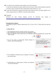
3. Data Transfer Software Installation Guide◆NOTE!・ If an earlier version of Data Transfer Software is installed, uninstall it, and theninstall this version of Data Transfer Software.(1) Macintosh versiona) SetupIn order to use Data Transfer Software, you first need to install the applicationand the USB driver from the bundled CD-ROM.Follow the steps below to install.b) Operating environmentSoftwareData Transfer Software (this software)USB driver *1MacOS X 10.5 IntelCPUOS *2MacOS X 10.6 IntelCPU (32/64bit mode)MacOS X 10.7 IntelCPU (32/64bit mode)Models*3 *4Macintosh with a standard USB interfaceCPUIntel CPU (compatible with operating conditions ofOS) *3RAMCompatible with operating conditions of OSHard disk space Same as aboveDisplayScreen resolution: At least 1024 x 768, Color quality:At least 16-bit*1 L-758 series only*2 If you are using a Macintosh computer, be sure to use the Macintoshversion of the software. Operation of the Windows version is notguaranteed when running in Virtual PC for the Mac.*3 Intel CPU dedicated. 68k computers and Power PCs not supported.*4 ・The operating system must be the one preinstalled on the computer.・Proper operation may not be possible on certain Macintosh modelsand configurations.・Proper operation is not guaranteed on a Macintosh with an upgradedoperating system or an add-on USB interface.・Proper operation is not guaranteed over connections through a USBhub.・A drive capable of reading a CD-ROM is required to install the software.26
c) Installing the software1. Turn on your Macintosh and start up MacOS X.2. Set the bundled CD-ROM into the CD-ROM drive of your Macintosh.3. Open the folder which is applied to the OS version to install in CD-ROM.4. To start the installation, double-click the "Data Transfer Software(3.0). pkg"icon.5. Click the [Continue] button.6. The license agreement is displayed. Select [English], read the agreement, andthen click the [Continue] button.27
◆NOTE!・ If an earlier version of Data Transfer Software is installed, uninstall it, andthen install this version of Data Transfer Software.・ If you select a language that differs from that of the OS on your computer,Data Transfer Software can be installed, but corrupted characters may bedisplayed.If you accidentally install the wrong language version of Data TransferSoftware, first uninstall it, and then re-install the correct language version.For information about uninstalling the software, see "d) Uninstalling thesoftware". (See page 29)7. After reading the licenseagreement, click the [Agree]button if you agree to its termsand conditions.8. Confirm that the installation folder volume is correct, and then click the[Continue] button.If you want to install in a different [folder], clickthe [Select] button and then select the folderyou want.9. You are now ready to install Data TransferSoftware.To continue, click the [Install]button.28
10. Authentication is run.Make entries in “Name” and“Password” and click the [InstallSoftware] button.11. Next , install the USB driver.To continue installing, click the[Continue] button.12. Installation is now complete.You must restart yourcomputer after the installation,so click the [Restart] button.The computer restarts.d) Uninstalling the software◆NOTE!・ Perform the following procedure only if you no longer want Data TransferSoftware installed on your computer.◆Reference・ The profile data remains even if the application is uninstalled.If you want to completely delete the profile data, select [Delete] Profilesbefore uninstalling the application. (See page 46.)29
For MacOSX 10.51. Quit all applications that are currently running on your computer.2. Open "Macintosh HD" and then double-click the "Applications" folder.3. Select the “SEKONIC” folder, double click on the “SEKONIC LightmeterUninstaller app” and start USB driver uninstall.4. You are now ready to uninstallData Transfer Software. Tocontinue, click the [Uninstall]button.5. The uninstallation confirmationscreen is displayed. To continue,click the [OK] button.6. Authentication is run. Makeentries in “Name” and“Password” and click the [OK]button.7. Uninstallation is now complete.Click the [OK] button.30
8. Now delete the application.Select the “SEKONIC” folderin the “Application Folder” anddrag-and-drop it in theRecycle Bin (Trash) to deleteit.For MacOSX 10.6 and 10.71. Quit all applications that are currently running on your computer.2. Open "Macintosh HD" and then double-click the "Applications" folder.3. Select the “SEKONIC” folder, double click on the“SEKONIC_Lightmeter_Uninstaller(MACOS10.6_10.7).pkg”and start USB driver uninstall.4. Click the [Continue] button.5. Select a Destination, and clickthe [Continue] button.31
6. You are now ready to install Data Transfer Software.To continue, click the [Install]button.10. Authentication is run.Make entries in “Name” and“Password” and click the[Install Software] button.11. Next , uninstall the USB driver.To continue installing, click the[Continue Installation] button.12. Uninstallation is now complete.You must restart yourcomputer after the installation,so click the [Restart] button.The computer restarts.32
13. Now delete the application. Select the “SEKONIC” folder in the“Application Folder” and drag-and-drop it in the Recycle Bin (Trash) todelete it.33
(2) Windows versiona) SetupIn order to use Data Transfer Software, you first need to install the applicationand the USB driver from the bundled CD-ROM.Follow the steps below to install.b) Operating environmentSoftwareData Transfer Software (this software)USB driver *1Windows ® XP (32-bit version) * 2OSWindows ® Vista (32-bit version) * 3Windows ® 7 (32-bit version)/Windows ® 7 (64-bit version) * 4Models PC equipped as standard with USB interface *5CPUCompatible with operating conditions of OSRAMSame as aboveHard disk space Same as aboveDisplayScreen resolution: At least 1024 x 768, Color quality:At least 16-bit*1 L-758 series only.*2 Home Edition/Professional Edition, SP3 upward*3 Home Basic/Home Premium/Business/Ultimate, SP2 upward.*4 Home Basic/Home Premium/ Professional /Ultimate, SP1 upward.*5 ・The operating system must be the one preinstalled on the computer.・Proper operation may not be possible on certain computer models andconfigurations.・Proper operation is not guaranteed on a computer with an upgradedoperating system or an add-on USB interface, a homemade computer, ashop-made computer, or in an emulator environment (such as VirtualPC).・Proper operation is not guaranteed over connections through a USBhub.・A drive capable of reading a CD-ROM is required to install the software.34
c) Installing the software1. Turn on your PC and start up Windows.2. Load the USB driver file onto yourPC.The installer should start upautomatically when you set thebundled CD-ROM into theCD-ROM drive.When the screen to the right isdisplayed, click the [AutoRun.exe]button.◆Reference・ If the installer does not start automatically,double-click “AutoRun” on the CD-ROM.3. OS User Account Control askspermission to install the program.When the screen to the right isdisplayed, click the [Allow] button.35
4. When the screen to the right is displayed, select [English] in the dropdown list.Click the [Install] button.◆NOTE!・ If you select a language that differs from that of the OS on your PC, DataTransfer Software can be installed, but corrupted characters may bedisplayed.If you accidentally install the wrong language version of Data TransferSoftware, first uninstall it and then re-install the correct language version.For information about uninstalling the software, see "d) Uninstalling thesoftware". (See page 41.)5. Click the [Install] button.* The screen on the right will bedisplayed if the old version (Ver.1.2) of Data Transfer Softwaredriver is still installed.Click the [Yes] button.6. Click the [Install] button.36
7. Click the [Install] button.8. To continue installing theapplication software, click the[Restart Later] button.9. Next, install Data TransferSoftware.To continue, click the [ Next ]button.37
10. If you agree with the terms of the license agreement, select “I accept…” andthen click [ Next ].You cannot proceed if youselect “I do not accept…”.11. Confirm that you are installingthe software in the desired folder,and then click the [ Next ]button.If you want to change to adifferent folder, click the[Change] button and then selectthe folder you want.12. You are now ready to installData Transfer Software.To continue, click the [Install]button.38
13. A screen showing the progressof the Data Transfer Softwareinstallation is displayed.14. This completes installation of Data Transfer Software.Click the [Finish] button.◆NOTE!・ Depending on your operating system, your computer may prompt you torestart after you have installed the software.If you are prompted to restart, restart your computer immediately.39
15. If this is the first time you are connecting the light meter to your computer,proceed to Step 16.Install the hardware that is necessary for recognizing the light meter. Forinformation about connecting the light meter to your computer, see "4. BasicOperation". (See page 42.)Please also note that in the following installation, depending on the OS,environment and conditions, the displays in Steps 16 and beyond may notappear or their content may be different.16. The screen to the right is displayed. Click thedisplay area.17. The screen to the right is displayed, and theinstallation is finished.◆NOTE!・ Whenever you connect or disconnect the USB cable, be sure to do so in theproper sequence.Disconnecting the USB cable while data is being transferred may result inthe loss of data or circuit damage.40
d) Uninstalling the software◆NOTE!・ Perform the following procedure only if you no longer want Data TransferSoftware installed on your computer.1. Quit all applications that are currently running on your computer.2. From "My Computer," openControl Panel and thendouble-click "Uninstall aprogram".3. Select "Data Transfer Software"(or “Lightmeter L-758series”)and then click [Uninstall].4. A confirmation screen will appear,so click on the “Yes” button tostart uninstalling, and thenuninstall will be completed.◆Reference・ The profile data remains even if the application is uninstalled.If you want to completely delete the profile data, select [Delete] Profilesbefore uninstalling the application. (See page 46.)41
4. Basic Operation(1) How to connect the light meter to your computer1) USB cable is needed.◆NOTE!・ Use a USB (A) male to mini (B) male cable.2) Connect the USB cable to your computer.3) Check that the light meter is turned off.4) Connect the USB cable to the light meter.42
5) Turn on the light meter.If everything is connectedproperly, a USB icon will flash onthe light meter LCD screen.◆Reference・ While connecting with DataTransfer Software, the USB iconstays lit rather than flashing.6) Connection is now complete.Start Data Transfer Software in one of the ways described below.・ Macintosh versionClick the Data Transfer Softwareicon in the dock on the desktop.・ Windows versionDouble-click the icon (shown to the right) on your desktop.◆NOTE!・ When Data Transfer Software is running and the light meter is on, do notdisconnect the USB cable.If you do, Data Transfer Software may not operate properly when youreconnect the cable.If a communication error occurs, first quit Data Transfer Software, followthe instructions in “(1) How to connect the light meter to yourcomputer” to reconnect the USB cable, and start Data Transfer Softwareagain.(See page 42.)43
(2) How to disconnect the light meter from your computer1) Quit the Data Transfer Softwareapplication.2) Turn off the light meter. TheUSB icon disappears from theLCD screen.3) Disconnect the USB cable fromthe light meter.4) Disconnect the USB cable fromthe computer.◆NOTE!・ To ensure that the light meter remains water-tight, be sure to close theUSB port cover whenever you are not using the meter.44
5. Data Transfer Software Operations(1) Main Screen Explanation(The screens from the Macintosh version are used in the following explanation.)Once the Data Transfer Software opens,the menu bar [ I ] and main screen [ II ]will be displayed. By switching betweenthe tabs on the main screen, thefollowing four screens can be displayed.I[1] Exposure Profile (See page 51)[2] Custom Setting (See page 79)[3] User Setting (See page 79)[4] Update Settings (See page 80)IIDouble click on a tab title to switch tothat screen.(2) Menu bar and functionsThe menu bar contains five menus.a) Data Transfer SoftwareThis menu contains the basic Data TransferSoftware operation commands.1. About SEKONIC Data Transfer SoftwareShows the version and system information forData Transfer Software you are using.2. Quit SEKONIC Data Transfer SoftwareQuits Data Transfer Software.◆Reference・ These commands are in the following locations in the Windows version.About SEKONIC Data Transfer Software: Menu bar – HelpExit SEKONIC Data Transfer Software: Menu bar – Profiles45
) ProfilesContains general operation commands forcamera exposure profiles.1. Create New ProfIleAllows you to create a camera exposure profile.(Same operation as the Create New ProfIlebutton in the Main screen)2. View Profile Data/PrintAllows you to check and print the camera exposure profile data you created.(Same operation as the View Profile Data/Print button in the Main screen)3. Edit ProfileAllows you to edit the camera exposure profile you created.(Same operation as the Edit Profile button in the Main screen)4. Data Transfer to Light meterAllows you to transfer the camera exposure profile you created to the lightmeter.(Same process as the Data Transfer to Light meter button in the Mainscreen.)5. ImportUse this command to add the camera exposure profile you created in DataTransfer Software on a different computer to the Camera Exposure Profile Listin Data Transfer Software on the computer you are using.6. ExportUse this command to copy the camera exposure profile you created in DataTransfer Software to a different computer.7. DeleteAllows you to delete a camera exposure profile.You can start the same operation by selecting the camera exposure profile inthe Camera Exposure Profile List in the Main screen and right-clicking it (orholding down the “ctrl” key and clicking it).46
8. RenameAllows you to change the name of a camera exposure profile.You can start the same operation by selecting the camera exposure profile inthe Camera Exposure Profile List in the Main screen and right-clicking it (orholding down the “ctrl” key and clicking it).◆NOTE!・ Camera exposure profiles to be exported are normally saved as “Ver. 3”formats for Data Transfer Software Ver. 3.0. For Data Transfer SoftwareVer. 2.0, select “Ver. 2.” as the formatwhen saving.・ Profiles created in Manual Mode cannotbe exported in the “Ver. 2” format.c) Edit ProfileContains commands that help input operations in the camera exposure profilename input screen.1. CutAllows you to cut some of the characters that have been entered in the cameraexposure profile name input screen.You can start the same operation by clicking a camera exposure profile in thescreen that allows you to select a camera exposure profile name andright-clicking it (or holding down the “ctrl” key and clicking it).2. CopyAllows you to copy some or all of the characters that have been entered in thecamera exposure profile name input screen.You can start the same operation by clicking a camera exposure profile in thescreen that allows you to select a camera exposure profile name andright-clicking it (or holding the “ctrl” key and clicking it).3. PasteAllows you to paste the characters that were cut or copied in the cameraexposure profile name input screen.You can start the same operation by clicking a camera exposure profile in thescreen that allows you to select a camera exposure profile name andright-clicking it (or holding the “ctrl” key and clicking it).47
d) OptionsContains option functions in Data Transfer Software.1. Defaults of Calculation Setting ChangeAllows you to change the default values forDynamic Range (+), Clipping Point (+), MiddleTone, Dynamic Range (-) and Clipping Point (-)when you create a new camera exposureprofile.Click the level value for the item you want to change, and enter the prescribedlevel value from the keyboard.Note that you can click the Defaults button to return the settings to the <strong>Sekonic</strong>standard values.Click the OK button after you have changed thesettings to enable the settings and return to theMain screen.◆NOTE!・ If you changed the Dynamic Range/Clipping Point settings in Advancedmode or by changing the exposure range, only the selected cameraexposure profile is changed.Note that the default level value always takes precedence when you createa new camera exposure profile.2. Save Backup Profile to ComputerLoads the data from the camera exposure profile set in the light meter onto thecomputer and saves it.3. Transfer Backup Profile to Light meterLoads the data from the camera exposure profile saved on the computer andtransfers it to the light meter..You can use this command on data from a camera exposure profile created inan earlier version of Data Transfer Software.48
◆NOTE!・ Backup profiles are in a different file format (“.csv” extension) thancamera exposure profiles created in Data Transfer Software (“.spf”extension) so that they can be transferred to the light meter, so beaware of the following points.‣ Multiple camera exposure profiles on the light meter are managedas a single file. (You cannot manage only the camera exposureprofiles you want.)‣ You can check the data in a backup profile, but you cannot edit it.‣ You cannot create characteristic curve graphs from the data in abackup profile.‣ Profiles created in the older version (Ver. 1.2) of Data TransferSoftware are in the same CSV format as files after they have beentransferred to the light meter. Therefore, if you want to transfer aprofile created in an older version of Data Transfer Software to thelight meter, use Transfer Backup Profile.4. View the Current Profile of Backup DataAllows you to display and print details of a camera exposure profile that wasbacked up onto a computer from the light meterin a table.In the area outlined in red in the figure to theright, you can switch the camera exposureprofile to be displayed.Display and print the following settings for thecamera exposure profile shown in the table.1)Compensation Value2)Clipping Point (+)3)Dynamic Range (+)4)Dynamic Range (-)5)Clipping Point (-)◆NOTE!・ All of the settings in the camera exposure profile displayed in the screenare displayed using one of four combinations of light source type(ambient or flash) and measurement method (incident light or reflectedlight). Check the light source type and measurement method for thedata being displayed in the screen.49
5. Reset of Profile in Light meterAllows you to return a camera exposure profile in the light meter to the <strong>Sekonic</strong>standard values.Name Standard ValueClipping Point (+) +3.5Dynamic Range (+) +2.5Compensation Value 0.0Dynamic Range (-) -2.5Clipping Point (-) -3.56. Update Report Setting ScreenYou can decide whether or not to automatically receive update reportinformation on Data Transfer Software and light meter firmware on the <strong>Sekonic</strong>server.If the update report function is set to ON, communication with the <strong>Sekonic</strong>server will be established and update report information downloaded wheneveryou start the Data Transfer Software. When there is an update, the updateconfirmation screen will be displayed automatically.e) HelpAllows you to view the Software Guide (electronic version of this guide).50
(3) Exposure Profile Tab and FunctionsThe Exposure Profile Tab is the basic operations screen that is displayed whenyou start Data Transfer Software. The following frequent operations can be usedin the Exposure Profile Tab.Create New ProfileView/Print ProfileProfile EditTransfer to Light Metera) Create New ProfileAllows you to create a camera exposureprofile.The following 3 modes can be used tocreate camera exposure profiles. Quick ModeCreates a camera exposure profilefrom test exposure data containinglight meter measurements for a singlelight source (ambient or flash) and asingle ISO. Advanced ModeCreates a more accurate cameraexposure profile from test exposure data containing light meter measurementsfor each type of light source and each ISO.Further, with the Advance Mode, there are two modes available: the NormalMode for creating camera exposure profiles in an exposure range of +/-7EV aswell as the Expansion Mode for creating camera exposure profiles in anexposure range of +/-10EV. Manual ModeCreates a camera exposure profile from direct input of obtained from tests withother targets, general data supplied by themanufacturer or other testing service.1) Quick ModeClick the Create New Profile button in theExposure Profile Tab.The Select Profile Mode screen is displayed.Click the Quick Mode button.51
1. Select TargetSelect the exposure profile target used forthe test exposure.Click on the button heading the target nameto be used in test shooting.Click the Next button after you have madeyour selection.2. Measured ValueEnter the standard exposure values measured using the light meter when youtook the test shooting.Select the ISO seinsitivity, the incident /reflected light and the measurements (shutterspeed, aperture, 1/10 step measurements)from the pull-down menus.If the profile is for a digital CINE camera,switch ON the Cine mode. Instead of theshutter speed, frame rate and shutter openingangle setting column will be displayed, andyou can make your selections.Click the Next button after you have made all of your selections.◆NOTE!・ Be sure to either enter or check the measurements from the light meter.The differences between the light meter values and the exposure datafrom the test exposure are calculated as compensation values, so if youtransfer a camera exposure profile in which the wrong measurementswere entered, the measured values for the light meter will change.◆Reference・ The 1/10 step measurement is the fractiondisplayed in the aperture value area of thelight meter.52
3. Select Test ImagesSelect the folder that contains the testimages of the digital camera used to makethe camera exposure profile, and click theOpen button.The image data is displayed as thumbnailsin the folder. Select the necessary images.Click the white square in the top right of thethumbnail image to select it with acheckmark, which will be displayed in thewhite square.Target TypeNo. ofselectedimages53Exposure settings for selected imageExposure Profile Target II 3 Standard, +/-3EVExposure Profile Target 11 Standard, each step of +/-5EVColorChecker 3 Standard, +/-3EVOnce you select necessary images, Next button will be selectable and makesit possible to make another selection.If you have selected the correct images, click the Next button.◆Reference・The image formats that can be loaded are JPEG and TIFF. (RAW datacannot be loaded.)If you selected the wrong folder, click the Select Folderbutton and reselect the folder containing the test exposure data.Note that it is easier to select images if you separate the test shooting imagesby saving in separate folders by each ISO and light source.・When you click a thumbnail image, apreview is displayed and Exif information isdisplayed on the left side of the screen.Check the Exif information as you selectyour images. If you select an image inwhich Exif information is not embedded, ascreen for entering image exposureconditions appears.
4. Analyze DataSpecify the range on the test image forautomatically loading patch densities.Click on the displayed thumbnail for theimage for specifying the range. (The autopositioning function will overlay green crossmarks to on the four cross marks inthe corners of the thumbnail.) If the greencross marks are not correctly positioned,they can be drag-and-drop maneuvered over the corner cross marks.◆Reference・ If you cannot see the cross marks in the four corners because the testimage is too overexposed or underexposed, use the Brightness ofPreview slider to adjust the preview.The auto positioning function uses thetarget’s white corner cross marks as thecriteria, so if a target without cross marks isbeing used, you will need to position thegreen cross marks manually.Set the reading range for all of the imagesusing the same procedure. If you selectedExposure Profile Target II or ColorChecker,you select three images, and if you selectedExposure Profile Target, you select 11 images. In either case, it becomespossible to select the Next button once you set the reading range on thenecessary images.When you click the Next button, image analysis starts and the characteristiccurve is calculated.54
◆Reference・ The cross marks are automatically placed in the same position as isaligned in the previous image. If the position of test image remains thesame, you can easily set the range by selecting the thumbnail imagesas is.We recommend that you fix the exposure profile target in place duringthe shooting.55
5. Profile GraphShows a graph of the sensitivity curve from the test image data.In the area of [ I ], the level value (under 8-bit) for each setting is displayed.In the area of [ II ], the distancesfrom the Middle Tone to thedynamic ranges and the clippingpoints are displayed in the EVvalues.I II6. Save as …To save the camera exposure profile youcreated, click the Save button.Next, the file name input dialog is displayed,so after entering the file name, click the OKbutton.After the profile is saved, the screen returnsto the Exposure Profile Tab.◆NOTE!・ Only single-byte alphanumeric characters are valid for use in cameraexposure profile names. You can enter up to 31 characters for the filename.・ In this Quick Mode, the exposure profiles created using a single ISOand a single light source, are also all reflected in other ISOs and lightsources.56
2) Advanced ModeClick the Create New Profile button in theExposure Profile Tab.The Select Profile Mode screen is displayed.Click the Advanced Mode button.1. Select TargetSelect the exposure profile target used for thetest exposure.Click the button in front of the target name toselect it.If you have selected ColorChecker, go ontoselect Classic, Passport or Mini.For selection of exposure range scale, selectNormal Mode to measure the +/-7EV range.Select Expansion Mode to measure +/-10EV range.Click the Next button after you have made your selection.2. Select Light SourceSelect the light source (ambient or flash) usedin the test shooting.Click the button in front of the light sourcename to select it.Click the Next button after you have madeyour selection.3. Measured ValueEnter the standard exposure values measuredusing the light meter when you took the testshooting.Select the ISO seinsitivity, the incident / reflectedlight and the measurements (shutter speed,aperture, 1/10 step measurements) from thepull-down menus.57
If the test shooting camera is not a still one but a movie camera, switch ONthe cine mode. Instead of the shutter speed, frame rate and shutter openingangle setting column will be displayed, and you can make your selections.Click the Next button after you have made all of your selections.◆NOTE!・ Be sure to either enter or check the measurements from the light meter.The differences between the light meter values and the exposure datafrom the test shoot are calculated as compensation values, so if youtransfer a camera exposure profile in which the wrong measurementswere entered, the measured values for the light meter will change.◆Reference・ The 1/10 step measurement is thefraction displayed in the aperture valuearea of the light meter.4. Select Test ImagesSelect the folder that contains the testimages of the digital camera used to makethe camera exposure profile, and click theOpen button.The image data is displayed as thumbnails in thefolder. Select the necessary images.Click the white square in the top right of thethumbnail image to select it with a checkmark,which will be displayed in the white square.58
Table 1Exposure rangescaleTarget typeExposureTarget IIExposureTargetProfileProfileNo. ofselectedimagesNormal ModeExposuresettings forselectedimages3 Standard,+/-3EV11 Standard,Each step for+/-5EVColorChecker 3 Standard,+/-3EVExpansion ModeNo. ofselectedimagesExposuresettings forselectedimages5 Standard,+/-4EV,+/-8EV21 Standard,each step for+/-10EV5 Standard,+/-4EV,+/-8EVOnce you select necessary images, Next button will be selectable andmakes it possible to make another selection.If you have selected the correct images, click the Next button.◆Reference・ The image formats that can be loaded are JPEG and TIFF. (RAW datacannot be loaded.)・ If you selected the wrong folder, click the Select Folder button andreselect the folder containing the test exposure data.Note that it is easier to select images if you separate the test shootingimages by saving in separate folders by each ISO and light source.・ When you click a thumbnail image, a preview is displayed and Exifinformation is displayed on the left side ofthe screen. Check the Exif information asyou select your images.Note that if you select an image in whichExif information is not embedded, ascreen for entering image exposureconditions appears.59
5. Analyze DataClick on the displayed thumbnail for the image for specifying the range. (Theauto positioning function will overlay green cross marks to on the fourcross marks in the corners of the thumbnail.)If the green cross marks are not correctly positioned, they can bedrag-and-drop maneuvered over the corner cross marks.◆Reference・ If you cannot see the cross marks in the four corners because the testimage is too overexposed or underexposed, use the Brightness ofPreview slider to adjust the preview.The auto positioning function uses the target’s white corner cross marks asthe criteria, so if a target without cross marks is being used, you will need toposition the green cross marks manually.Set the range for all of the images usingthe same procedure.Only the number of images for “No. ofselected images” in Table 1 (page 49)need be set as the reading range forimages to enable selection of the Nextbutton.When you click the Next button, imageanalysis starts and the characteristiccurve is calculated.60
◆Reference・ The cross marks are automatically placed in the same position as is alignedin the previous image. If the position of test image remains the same, youcan easily set the range by selecting the thumbnail images as is.We recommend that you fix the exposure profile target in place during theshooting.61
6. Profile GraphShows a graph of the sensitivity curve from the test image data.In the area of [ I ], the levelvalue (under 8-bit) for eachsetting is displayed.If you directly enter the levelvalue from the keyboard, youcan change the exposure I IIIrange.IIThe triangle cursors in thesensitivity curve graph[clipping point (+/-) anddynamic range (+/-) points]move in response to thelevel value you enter, and theEV scale value changes as well.If you click the mouse on the triangle cursors [clipping point (+/-) and dynamicrange (+/-) points] in the area of [ II ], you can drag and drop them to changethe exposure range.The level value and the EV scale change according to the new positions ofthe triangle cursors.In the area of [ III ], the difference in the number of exposure steps (EVscale) from the Middle Tone is displayed. You can change the exposurerange by directly entering the difference in the number of exposure steps (EVscale) from the keyboard.The level value as well as the triangle cursors on the sensitivity curve graphmove according to the difference in the number of steps (EV scale) that isentered.◆NOTE!・ The size relationship between the five points is in order from dynamicrange (-) ≦ clipping point (-) ≦ Middle Tone ≦ clipping point (+) ≦dynamic range (+), so the level value input or the cursor movementcannot deviate from this order.62
◆Reference・ The operations in [ I ], [ II ] and [ III ] in the sensitivity curve graph displayscreen are mutually connected. If you make a change to one of them, theresult is reflected in all of them.・ A rough summary of the dynamic range and clipping point settings is givenbelow.1) Dynamic range: Range of the number of exposure steps that can bereproduced on the digital camera being used, from theshadow areas to the highlight areas. Set the highest valuein Dynamic range (+) and set the darkest shadow value inDynamic range (-).2) Clipping point : Area where the contrast between light and dark in animage is clear with respect to the changes in EV values.Set the two end points in the area on the sensitivity curvegraph where the slope of the curve is linear (straight line).Note that the change between light and dark in the image(contrast) between the dynamic range and the clippingpoint is more gradual with respect to the changes in EVvalues.・ If you need to consider standards for printing, you can set the level valuesthat can be rendered during printing in the clipping points, and set thedynamic ranges outside of clipping points.・ It is easier to use the triangle cursors (4) to set the level values at the clippingpoints and dynamic ranges based on the characteristic curve graph.・ If the clipping poits and dynamic ranges are decided in advance, it isconvenient to set by entering numbers directly63
7. Add ISO/Light SourceYou can click the Add ISO/Light Source button to add the data of differentISOs and light sources to the camera exposure profile currently being createdin order to increase the accuracy of the profile.To add the data, click the Add ISO/Light Source button. NOTE!・ In Advanced Mode, profiles created with only one ISO and light sourceare also all reflected in the other ISOs and light sources. By using AddISO/Light Source, you turn the profile created from the test image intoactual measured values, and profiles with ISOs in between areautomatically calculated, which increases the accuracy. Reference・ When you select Add ISO/Light Source, you are repeating theoperations from “2. Select Light Source” to enter the data.・ While you are adding a profile, the ISO displayed in blue characters inthe pull-down menu displayed in the “3.Measured Value” screenindicates that exposure profile data already exists. (In the Windowsversion, a red checkmark is placed Next to the ISO.)8. SaveTo save the camera exposure profile youcreated, click the Save button.Next, the file name input dialog is displayed.Enter the file name and click the OK button.After the profile is saved, the screen returns tothe Exposure Profile Tab screen.◆NOTE!・ Only single-byte alphanumeric characters are valid for use in cameraexposure profile names. You can enter up to 31 characters for the filename.64
3) Manual ModeClick the Create New Profile button in the Exposure Profile Tab.The Profile Mode Selection Screen will be displayed, so click the ManualMode button.ⅠⅢⅤⅣⅡ1. In the area highlighted by [ I ], select type of light source and measuringsystem.2. In the area highlighted by [ II ], select the sensitivity specific data related tothe ISO sensitivity you want to change.3. The following are the two methods for inputting numeric values.(a) Input using light range scale [ III ]If you click the mouse on the triangle cursors, you can drag and dropthem to change the exposure range. Move the red triangle cursors tochange the dynamic range and move the green triangle cursors tochange the cropping range. The positions of the triangle cursors areintegrated with each of the numeric values of the dynamic range andcropping range.65
(b) Direct input of numeric values [ IV ]Place the mouse at a location to be changed, and double click toenable direct value input.4. To change sensitivity specific data for other ISO sensitivity, repeat items 2and 3.5. Once a sensitivity specific data line has been changed, the ISO sensitivitywill turn blue [ V ]. (With the Windows version, a red check mark is added infront of the ISO sensitivity.) If you double click the ISO sensitivity or the redcheck mark, the changed settings will be deleted, and the settings will returnto the default ones.6. Click the Save button to save the created camera exposure profile. Next,the file name input dialog is displayed. Enter the file name and click the OKbutton. After the profile is saved, the screen returns to the Exposure ProfileTab screen.◆NOTE!・ Only single-byte alphanumeric characters are valid for use in cameraexposure profile names. You can enter up to 31 characters for the file name.66
) View Profile Data/PrintAllows you to check and print the camera exposure profile data you created.You can view and print camera exposure profiles using one of the following twoView/Print modes. Single profileAllows you to display a data table and a graph for a single camera exposureprofile to view or print. Multiple profilesAllows you to display sensitivity curves for multiple camera exposure profilesin the same graph to view or print.You can also display sensitivity curves for each ISO in a single cameraexposure profile in the same graph to view or print.(1) Single ProfileClick the View Profile Data/Print button inthe Exposure Profile Tab.The Select Profile screen is displayed. Clickthe Single Profile button.In “Single Profile” there are “Data Table” and“Graph” screens. [ I ] Data TableAllows you to check a list of the data to betransferred to the light meter. GraphAllows you to visually check a cameraexposure profile using a sensitivity curve graph.1. Data Table displaySelect the profile you want to view in Profile Name.Select the camera exposure profile from the [ II ] Profile Name pull-downmenu.Then make selections in [ III ] Light Source, Measuring Mode.IIIIII67
To print, click the Print button.To continue, follow the instructions for your printer.Click the Page Setup button to makeprint settings.To continue, follow the instructions foryour printer to make the settings.Click the Preview button to previewthe print.◆Reference・ The ISOs in blue in the “Data Table” and “Graph” screens are actualmeasurements calculated from the test image data.(In the Windows version, a red checkmark is placed next to the ISO.)The ISOs in black are calculated values obtained through simulation.2. Graph displaySelect the profile you want to view in“Profile Name” [ I ].Select the camera exposure profilefrom the Profile Name pull-downmenu.Then make selections in [ II ] LightSource, Measuring Mode and ISOsensitivity [ III ].ⅢⅡⅠThe widths of the dynamic rangeand the clipping point in the cameraexposure profile are indicated by thenumber of exposure steps (EVscale) at the bottom of the graph.68
To print, click the Print button. Tocontinue, follow the instructions foryour printer to print.Click the Page Setup button tomake print settings.To continue, follow the instructionsfor your printer to make the settings.Click the Preview button to preview the print.◆Reference・ The graph of the measured values obtained from the exposure data isdisplayed in solid lines, and the graph of the calculated values obtainedthrough simulation is displayed in dotted lines. The simulation calculatesthe difference in EV between two ISOs with actual measurementswhen a difference in EV in the dynamic range and clipping point occursbetween two ISOs so that the change is uniform.・ Because the Manual Input Mode includes only the minimum andmaximum dynamic range points, the system has no data to create asensitivity characteristic curve. Therefore no Graph will be producedfrom the data.(2) Multiple ProfilesClick the View Profile Data / Print button inthe Exposure Profile Tab.The Select Profile screen is displayed. Clickthe Multiple Profiles button.In Multiple Profiles there are [ I ]Camera Comp and ISO Comp screens. Camera ComparisonAllows you to display and compare the sensitivity curves from multiplecamera exposure profiles in the same graph. ISOs ComparisonAllows you to display and compare the sensitivity curves for each ISO in asingle camera exposure profile in the same graph.69
1. Camera Comparison displayMake selections in the [II] LightSource, Measuring Mode and ISOsensitivity. pull-down menus.Then select the camera exposureprofiles you want to compare in the[ III ]Profile Name pull-down menu.You can compare up to five cameraexposure profiles.To print, click the Print button. Tocontinue, follow the instructions foryour printer to print.Click the Page Setup button tomake print settings.To continue, follow the instructionsfor your printer to make the settings.IIIIIIClick the Preview button to preview the print.2. ISOs Comparison displaySelect the comparison conditions from the Light Source and MeasuringMode pull-down menus.Next, select the camera exposure Iprofile for which you want to compareISOs in the Profile Name pull-downIImenu.Then select the ISOs you want to IIIcompare in the “ISO” pull-downmenu.You can display up to five ISOs at thesame time.Select the comparison conditions from the Light Source and MeasuringMode [ I ] pull-down menus.Next, select the camera exposure profile for which you want to compare ISOsin the Profile Name [ II ] pull-down menu.Then select the ISOs you want to compare in the ISO [ III ] pull-down menu.You can display up to five ISOs at the same time.70
To print, click the Print button. Tocontinue, follow the instructions foryour printer to print.Click the Page Setup button tomake print settings.To continue, follow the instructionsfor your printer to make the settings.Click the Preview button to preview the print.71
c) Edit ProfileAllows you to edit a camera exposure profile.You can edit a camera exposure profile using one of the following two modes. Change Exposure RangeAllows you to change the clipping point (+/-) and the dynamic range (+/-) forthe camera exposure profile you created. Add ISO/Light SourceAllows you to add shoot data of other light sources and ISO sensitivities tothe camera exposure profile you already created to increase the accuracy ofyour camera exposure profile. Add Profile (Manual Mode)Allows you to add shoot data of other light sources and ISO sensitivities tothe camera exposure profiles created in manual mode.(1) Change Exposure RangeAllows you to change the clipping point anddynamic range settings while viewing thesensitivity curve graph.Click the Edit Profile button in the ExposureProfile Tab.The Select Edit Mode screen is displayed.Click the Change Exposure Range button.1. Select the camera exposure profile.Select the camera exposure profile whose exposure range you want tochange in the Profile Name pull-down menu.Then make selections in Light Source, Measuring Mode and ISOsensitivity.72
◆NOTE!・ The exposure range changes are made to the actual measurements,so only the actual measurement graph is displayed. The ISOs in blueare actual measurements analyzed from the test images. (In theWindows version, a red checkmark is placed next to the ISO.)・ The camera exposure profiles created in accordance with normal shootdata are the profiles accommodated by “Change Exposure Range”. Tochange profiles created in Manual Mode, use “Add Profile (ManualMode)”.2. Change the exposure rangeThe sensitivity curve graph forthe camera exposure profile is I IIIIIdisplayed.In [ I ], the preset level value (0to 255) under the 8-bit isdisplayed.If you directly enter the levelvalue from the keyboard, youcan change the exposure range.The triangle cursors in the sensitivity curve graph (clipping point +/- anddynamic range +/- ) move in response to the level value you enter, and the EVscale value changes as well.If you click the mouse on the triangle cursors (clipping point +/- and dynamicrange +/- ) in the area of [ II ], you can drag and drop them to change theexposure range.The level value and the EV scale change according to the new positions ofthe triangle cursors.In the area of [ III ], the difference in the number of exposure steps (EV scale)from the Middle Tone is displayed. You can change the exposure range bydirectly entering the difference in the number of steps from the keyboard.The level value as well as the triangle cursors on the sensitivity curve graphmove according to the difference in the number of steps that is entered.◆NOTE!・ The size relationship between the five points is in order from dynamicrange (-) ≦ clipping point (-) ≦ Middle Tone ≦ clipping point (+) ≦dynamic range (+), so the level value input or the cursor movementcannot deviate from this order.73
3. Finish changing the exposure range.When you click the Backbutton, a save confirmationdialog is displayed.To save the settings, selecteither Overwrite or Save As.If you do not want to save thesettings, select either Don’tSave (Quit Without Saving)or Cancel (Return toChange Exposure RangeScreen) to finish.(2) Add ISO/Light SourceClick the Edit Profile button in the Exposure Profile Tab.The Select Edit Mode screen isdisplayed. Click the Add ISO/LightSource button.1. Select the camera exposure profileThe Select a profile to modify screen isdisplayed. Select the camera exposureprofile with the different light source andISO sensitivity you want to add, and clickthe OK button.After this, the operations are the same asfor creating a new profile in AdvancedMode. (See page 57.)74
◆NOTE!・ The camera exposure profiles created in accordance with normal shootdata are the profiles accommodated by “Add Profile”. To make changesto profiles created in Manual Mode, use “Add Profile (Manual Mode)”.(3) Add Profile (Manual Mode)Click the Edit Profile button in theExposure Profile Tab.The Select Edit Mode screen will appear,so click the Add Profile (Manual Mode)button to select.1. Select Camera Exposure ProfileThe Select Profile screen will be displayed,so select the camera exposure profile youwant to add and click the OK button.The operations from here on are thesame as creating a new profile inManual Mode (see page 65).◆NOTE!・ The camera exposure profiles created using Manual Mode are theprofiles accommodated by Add Profile (Manual Mode). This mode cannotbe used to add profiles to work already created using normal shoot data. .75
d) Transfer to Light meterTransfer the camera exposure profile you created to the light meter.1. Connect the light meter.Connect the light meter to your computer with a USB cable, and then turn onthe light meter.The Selected Profile becomes active, and the camera exposure profiles setin the light meter are displayed in Current Profiles Setting.Connect tolight meter2. Select the camera exposure profile.Click the camera exposure profile you want to set in the light meter in“Camera Exposure Profile List” in the Main screen to select it.(The selected camera exposure profile is highlighted in blue.)Click the line numbers you want to set from within the selected profile.(The selected line background color will become inverted.)Click the button and set the selected camera exposure profile in theselected profile.The Transfer to Light meter button becomes active.76
◆Reference・ You can drop and drag the camera exposure profiles that you want toset in the light meter from within the Camera Exposure Profile List tothe selected profile. You can move the profiles by using the mouse todrag in the selected profiles.3.Cancel the selected camera exposure profileIf there is no camera exposure profile set, the selected profile column willbe empty. So, if you want to keep the current profile set in the actual lightmeter, leave the selected profile column empty.Note that if you set a profile by mistake, you can click the Clear button toreturn to an empty column.◆Reference・ The forward setting for camera exposure profiles does not have to beset for all selected profiles. Therefore, when you want to change No.1 for the light meter, just set the camera exposure profile for No. 1, andtransfer the data, leaving the other columns empty. When columns areempty, the camera exposure profiles saved in the light meter will not beoverwritten.77
4. Transfer to the light meter.Click the Transfer to Light meter button.A dialog is displayed, and a message saying “Overwrite the profile data in thelight meter?” is displayed. Click the OK button to continue transferring thedata.If the data is transferred successfully, a dialog is displayed saying, “Profiletransfer completed” to inform you that the transfer is complete. Click the OKbutton to finish.78
(4) Custom Setting/TabYou can display the contents of customsetting on the connected light meter, andyou can transfer on-screen changes tothe light meter.Displaying and changing the contents ofcustome setting can be done only whenthe light meter is connected.Click the setting line you want to change,and then click the Contents of setting todisplay the setting value pull-down menu,and enable selection of other setting values.◆Reference・ For Windows, double click the “Contents of setting” to display thepull-down menu of other setting values.After changing the settings on screen, press the Transfer to Light Meter button torewrite the settings of the actual light meter.If you press the bottom left Default Setting button, all the settings on screen will bereset to those at time of shipping. If you want to return the settings of the light meterto the initial ones, press the Transfer to Light Meter button as well.(5) User Setting/TabThis function could not be used with theL-758 Series.79
(6) Update Settings/Taba) Update ScreenThis screen is for displaying the updateconfirmation screen.Press the Update Confirmation buttonto open the update confirmation screen.b) Update Confirmation ScreenBased on update information provided by connecting to the <strong>Sekonic</strong> web site,you can use this screen to confirm light meter firmware as well as the latestversion of Data Transfer Software, and download them to update.ⅠⅡ80
[ I ] FirmwareUpdate ButtonWhen a newer version of the firmware for the connected light meter hasbeen released, the Update button will become activated and ready to bepressed. Press the Update button to start downloading the newer firmware,and when the download is complete, the update will take placeautomatically.[ II ] Data Transfer SoftwareUpdate ButtonWhen a newer version of your Data Transfer Software has been released,the Update button will become activated and ready to be pressed. Press theUpdate button to start downloading the newer software, and when thedownload is complete, the update will take place automatically, followed bya restart of the equipment.Back ButtonThe Back button closes this screen.◆NOTE!・ The firmware for light meter is displayed while light meter is connectedwith computer. In case that it is not impossible to connect with <strong>Sekonic</strong>website, the version number doesn’t appear in “Latest Version”.The update function cannot be used if <strong>Sekonic</strong>’s web site(www.sekonic.co.jp) cannot be viewed with the internet connection beingused with the personal computer running the Data Transfer Software.If HTTP proxy server settings are required for use of a web browser, besure to make the same settings in the client proxy setting screen.Data Transfer Software cannot be used for other operations during theupdate (from pressing the Update button until update is completed).81
c) Update Notification Setting ScreenThe update notification settings are in Options (O) of the menu bar.When the Data Transfer Software Update Notification setting is ON, you willbe automatically notified about update information. The Update ConfirmationScreen will be displayed automatically when a new version becomes available.When the Firmware Update Notification setting is ON, you will be automaticallynotified about update information. The Update Confirmation Screen will bedisplayed automatically when a new version becomes available.Function Setting Notification Method Update MethodIf a new version exists on the The user presses the Updatewebsite, the “Updatebutton at the UpdateONConfirmation Screen” will be Confirmation Screen to update.displayed automatically. ThisData TransferSoftwareUpdateNotificationscreen will not be displayed ifthere is no new version.There will be no notifications. The user manually presses theUpdate Confirmation button atthe Update Setting Screen, toOFFdisplay the display the UpdateConfirmation Screen, and thenpresses the Update button toupdate.82
FirmwareUpdateNotificationONOFFIf a version of the light meterfirmware newer than the one onthe connected light meter existson the website, the “UpdateConfirmation Screen” will bedisplayed automatically. Thisscreen will not be displayed ifthere is no new version.There will be no notificationsThe user presses the Updatebutton at the UpdateConfirmation Screen to update.The user manually presses theUpdate Confirmation button atthe Update Setting Screen, todisplay the display the UpdateConfirmation Screen, and thenpresses the Update button toupdate.If the Proxy button is pressed, the Client Proxy Setting Screen will bedisplayed.83
d) Setting Client ProxyIf HTTP proxy server settings are required in order to be able to use the updatenotification function, set them at this screen.If HTTP proxy server settings arerequired in the web browser settings ofthe personal computer loaded with theData Transfer Software, set them in thesame way at this screen.◆NOTE!・ If you change the settings at this screen, press the OK button in thisscreen and then also press the OK button in the Update NotificationSetting Screen.・ Use HTTP Proxy ServerCheck mark this to designate the HTTP proxy server available for thenetwork environment you are using.・ AddressDesignate the address of the HTTP proxy server.・ PortDesignate the port number for the HTTP protocol.If user ID is required to access the proxy server, set user name andpassword as follows.・ User nameDesignate user name for HTTP protocol.・ PasswordDesignate password for HTTP protocol.84
6. Appendix(1) About ExposureThere are two exposure values: a standard exposure value and a properexposure value. Understanding the meanings of these two exposure values is thekey to better photography.a) Standard Exposure ValueExposure values (EV) are calculated based on illuminance (in the case of anincident light meter), or luminance (in the case of a reflected light meter). Thecalculation formulas used by these light meters contain constants called"calibration constants," which are the values that produce the differences in EVvalues. These constants are defined for specific ranges by each manufacturer.These values are what the manufacturers use to set their standard exposurevalues.Note that since this explanation is based on the image reproduction, the term“Middle Tone” is used in Data Transfer Software (application),.◆ReferenceThe following are the calibration constants used in <strong>Sekonic</strong> light meters.Incident Light Meter Calibration Constant: C=340 (Lumisphere)C=250 (Lumidisc)Reflected Light Meter Calibration Constant: K=12.5b) Proper Exposure ValueTo obtain the final images they want, skilled photographers often modify theexposure values displayed in light meters based on their instincts and personalpreferences. This means that depending on the photographer's intentions, adifferent exposure value may be used even when shooting the exact samesubject.For example, when taking a picture of a forest that has rays of sunlight shiningbrightly between the trees.If a photographer wants to highlight the rays of sunlight, he would measure theentire scene and use an exposure lower than the standard exposure to darkenthe trees, which makes the appearance of the sunbeams more striking. In thiscase, the proper exposure value is one that produces less exposure.On the other hand, if the photographer wants to capture the mood inside theforest while still maintaining the image of the rays of sunlight shining through, hemight measure the entire scene and use an exposure somewhat higher than thestandard exposure. In this case the higher value would be the proper exposurevalue.The proper exposure value is the one that produces the image that thephotographer is trying to achieve.85
(2) Sensitometry"Sensitometry" is a term that was created by combining the words "sensitivity" and"measurement".In the film camera era, a densitometer and other equipment were required tomonitor the color temperature and brightness of the light source, exposure time andconditions, developing time, and film image density, equipment that most peopledid not have.With the dawn of the digital camera age, however, image editing software hascreated an environment in which just about anyone can measure shootingconditions.Here we will explain how to use a digital camera with a light meter to obtain goodphotographs and provide an understanding of some of the thinking behindsensitometry.a) Sensitivity Characteristic CurveThis is a graph of the relationship between the amount of exposure (light source brightness+ subject reflectivity) and output (digital camera)The graph above is presented to help explaining sensitivity characteristics. Not alldigital camera characteristics are represented in this graph.In an actual camera, there would be three graphs, one each for R, G, and B.Here we will assume that all three colors have identical characteristics, so weshow only one graph.86
In this graph, brightness differences are expressed as EV values based on theMiddle Tone. The vertical axis of the graph is the output level (8-bit color).Level 0 is black, while level 255 is white.This graph shows how brightness differences in the subject will appear asbrightness differences on a photograph.More specifically, by using a light meter to measure the brightness of a subject, itis possible to know how the brightness will appear in the photograph based onthe exposure setting of the camera.For example, after you measure the highlights in a subject, you can determinenumerically whether the measured area can be reproduced photographically(without blooming or highlight block up). You also can numerically determinewhether the shadows can be reproduced photographically (without pixel noise orgrain).Some digital cameras have highlight and shadow warning functions, but theDigitalmaster L-758 series uses an EV scale, which makes it easier to check forblooming highlights or grain shadows using the number of aperture or shutterspeed steps.The graph above is one example to help explaining sensitivity curves.Digital cameras with red sensitivity curves have the widest exposure range,making them capable of reproducing from -4.5 EV to the Middle Tone on theshadow side and from approximately 3.2 EV from the Middle Tone on thehighlight side. (If the dynamic range (-) is 25 and the dynamic range (+) is 240 inData Transfer Software)87
In addition, if there is a steep curve near the Middle Tone for all of the red, blackand blue sensitivity curves, and the camera is capable of capturing data suchthat the further the curves move away from the Middle Tone, the flatter the curvesbecome. The amount of change in the output level will be the same as thebrightness near the Middle Tone, indicating that the camera is capable ofreproducing clear contrast between the highlights and the shadows. On the otherhand, if the change in output level is less than the change in brightness at a pointthat is far from the Middle Tone, this indicates that the camera is being made tobe more able to reproduce fine detail in the highlight and shadow areas, which isdifficult to reproduce, by controlling the density changes for the brightnesschanges.The purpose of finding out the characteristic curve of your digital camera is not tofind out if the characteristics are good or bad. By understanding thecharacteristics of your digital camera, you will be able to understand how it willreproduce the brightness of a subject that you measure using a light meter.If you can shoot with lighting that uses the maximum exposure range of yourdigital camera, you will be able to take shots that bring out the best characteristicsof your camera.◆ReferenceThe Middle Tone, dynamic range (-), clipping point (-), clipping point (+) and dynamicrange (+) settings will differ depending on how you think about image reproduction.At <strong>Sekonic</strong>, we use the following values as our default standard values. The numbers inparentheses indicate the standard range.Middle Tone 118 (113~123)Dynamic Range (-) 20 (15~25)Clipping Point (-) 35 (30~40)Clipping Point (+) 230 (225~235)Dynamic Range (+) 245 (240~250)88
) Middle ToneThe standard sensitivity level *1 of a digital camera is called the "Middle Tone" by<strong>Sekonic</strong>.For the standard range, <strong>Sekonic</strong> uses a setting of 113 to 123. If you feel thatthere is a difference between the measured data and the setting, you can adjustit to the appropriate value.From the test exposure data, Data Transfer Software finds the level value for theMiddle Tone that you set and calculates the difference between the exposureconditions that can be obtained from this Middle Tone value (aperture andshutter speed values) and the measured value from the light meter as the“Compensation Value”.*1 Standard Sensitivity Level: The sensitivity measurement standard value(118 in 8-bit color), is the Y-value (green) thatcorresponds to an 18% standard neutralgray subject when the digital maximumoutput (255 in 8-bit color) in the sRGB colorspace corresponds to a subject reflectivity of100%.c) Clipping PointThe clipping point means the range where the output level changes the sameamount with respect to the changes in photographic exposure. At <strong>Sekonic</strong>, therange from the Middle Tone in the highlight direction is called the "clipping point(+)", and the range in the shadow direction is called "clipping point (-)" . You canset 0 EV to +7 EV for clipping point (+) and -7 EV to 0 EV for clipping point (-).The setting range (level) should be set in accordance with the specifications ofthe digital camera you are using and what type of images you are trying toachieve.<strong>Sekonic</strong> uses the ranges of 225 to 235 for clipping point (+) and 30 to 40 forclipping point (-) as a guide. If you feel that there is a difference between themeasured data and the setting, you can adjust it to the appropriate value.*2 Photographic Exposure: This is the amount of light that reaches thesensor or film after passing through the lens.Put more simply, it is the brightness of thesubject.89
d) Dynamic RangeThe dynamic range means the range where the sensor output becomesgradually smaller with respect to changes in the photographic exposure, and isthe area where texture and tone can be photographically reproduced. At<strong>Sekonic</strong>, the range from the Middle Tone in the highlight direction is called the"dynamic range (+)", and the range in the shadow direction is called the"dynamic range (-)". You can set 0 EV to +7 EV for dynamic range (+) and -7EV to 0 EV for dynamic range (-).The setting range (level) should be set in accordance with the specifications ofthe digital camera you are using and what type of images you are trying toachieve.The values (especially on the shadow side) will depend on how much pluggingup you find acceptable in the shadows and how much blowing out you findacceptable in the highlights.<strong>Sekonic</strong> uses the ranges of 240 to 250 for dynamic range (+) and 15 to 25 fordynamic range (-) as a guide. If you feel that there is a difference between themeasured data and the setting, you can adjust it to the appropriate value.◆ReferenceIf you are shooting with printing in mind, you can make the following types ofsettings.Clipping point: Level values that can be rendered in printDaynamic range: Dynamic range or clipping point of the image that isphotographedAs a result, the brightness of the subject is not measured just by thecharacteristics of the digital camera sensor when you take the picture, it alsoconsidering the dynamic range for printing.90
7. Trouble-shootingThis section provides information about what to do when you encounter some of themost common problems that may occur while using Data Transfer Software. Beforecontacting <strong>Sekonic</strong>, check the information here to see if you can solve the problem onyour own.We recommend that you keep notes of messages that appear on your screen andother details. They will come in handy as you look for information in this troubleshootingguide and if you need to contact <strong>Sekonic</strong>.Make sure you first select “About SEKONIC Data Transfer Software” in the “DataTransfer Software” menu on the Macintosh computer to find out which version you areusing.In the Windows version, click on “About SEKONIC Data Transfer Software” in the“Help” menu to check the version of the software.ProblemThe installer does not startup automatically.Screen text characters arecorrupted.Recommended ActionNavigate to the CD-ROM on your computer anddouble-click "AutoRun".(Windows: See Page 35.)If you installed the wrong language version of the driverand Data Transfer Software, uninstall them. Nextre-install Data Transfer Software for the languageversion that matches the language of your operatingsystem.(Macintosh: See Page 29.) (Windows: See Page 41.)91
Cannot enter a file name.Enter up to 31 single-byte alphanumeric characters forthe file name. Double-byte characters are not supported.(See Page 56.)ProblemMy computer does notrecognize the light meter.A file saved on mycomputer will not open withData Transfer Software.Data Transfer Softwaresuddenly shut down.Recommended Action1.Use a computer that meets the Data Transfer Softwaresystem requirements. (Macintosh: See Page 26.)(Windows: See Page 34.)2.Connect the USB cable. (See Page 42.)3.Check whether or not the light meter is on.4.Complete driver installation.(Macintosh: See Page 27.) (Windows: See Page 35.)Editing a file with software other than Data TransferSoftware may make it unreadable by Data TransferSoftware.Be sure to use Data Transfer Software to edit files.1. When PC operation stopsRestart PC. (Data in mid-edit in Data Transfer Software willbe lost.)2. For Macintosh (if normal shutdown is not possible)(1) Press the PC’s Option + Command + Esc keys and forcequit the Data Transfer Software.(2) Restart Data Transfer Software. (Data in mid-edit in DataTransfer Software will be lost.)3. For Windows (if normal shutdown is not possible)(1) Press PC’s Ctrl + Alt + Delete keys and launch “TaskManager”.(2) Select “Application” tab and then select “Data TransferSoftware” above “Task”.(3) Press “End Task” button.(4) If the “Program not responding…” message appears,press the End Process button.(5) If a message saying that End is selected for nonresponding program Data Transfer Software. . exe…,press “Don’t send”.(6) Restart the Data Transfer Software. (Data in mid-edit inData Transfer Software will be lost).92
ProblemThe Data TransferSoftware text displayextends out too far.*Windows onlyThe graph line shifted.Recommended ActionFrom the Windows Control Panel, display the DisplayProperties dialog box.Select the "Settings" tab and then click the [Advanced]button.On the "General" tab, select "Normal size (96 DPI)" for"DPI setting".Restart your computer and then restart Data TransferSoftware. Note that any data being edited in DataTransfer Software will be lost at this time.)The exposure was incorrect when the shot was taken.・ Ambient light1. If you shoot using a shutter speed that is close to thecamera’s maximum speed, a difference arisesbetween the published value and the actual value,which may change the amount of exposure andcause the lines on the graph to shift.Adjust the amount of light (decrease the amount oflight) so that the camera shutter speed does notapproach its maximum speed.In addition, when you select an image in “Select TestImage”, enter the amount of shift in the light outputcorrection value.In the example to the left, the lowest data in the graphis shifting to the right, so enter a correction of about-0.3 EV.93
7-24-14, OIZUMI-GAKUEN-CHO, NERIMA-KU, TOKYO 178-8686 JAPANTEL: +81(0)3-3978-2335 FAX: +81(0)3-3978-5229http://www.sekonic.com/D75.1003_EN94Ver. 3.0